Fluke 1732 Calibration Manual
3540 fc logger/monitor
Hide thumbs
Also See for 1732:
- User manual (76 pages) ,
- Quick reference manual (2 pages) ,
- Quick reference manual (2 pages)
Table of Contents
Advertisement
Advertisement
Table of Contents

Related Manuals for Fluke 1732


Summary of Contents for Fluke 1732
- Page 1 1732/1734 1736/1738 3540 FC Logger/Monitor Calibration Manual March 2016 Rev. 1, 4/17 ©2016-2017 Fluke Corporation. All rights reserved. All product names are trademarks of their respective companies. Specifications are subject to change without notice.
-
Page 2: Limited Warranty And Limitation Of Liability
LIMITED WARRANTY AND LIMITATION OF LIABILITY Each Fluke product is warranted to be free from defects in material and workmanship under normal use and service. The warranty period is two years and begins on the date of shipment. Parts, product repairs, and services are warranted for 90 days. -
Page 3: Table Of Contents
Current Measurement ........... . . 22 AUX Input Check (1732/1734/1736/1738 Only) ....... . . 23 Optional Verification for Flexi or Clamp (Combined Logger and Probe Specifications) . - Page 4 1732/1734/1736/1738/3540 FC Calibration Manual...
-
Page 5: Introduction
Canada: 1-800-36-FLUKE (1-800-363-5853) • Europe: +31 402-675-200 • Japan: +81-3-6714-3114 • Singapore: +65-6799-5566 • Anywhere in the world: +1-425-446-5500 Or, visit Fluke's website at www.fluke.com. To register your product, visit http://register.fluke.com. To view, print, or download the latest manual supplement, visit http://us.fluke.com/usen/support/manuals. -
Page 6: Safety Information
1732/1734/1736/1738/3540 FC Calibration Manual Safety Information A Warning identifies hazardous conditions and procedures that are dangerous to the user. A Caution identifies conditions and procedures that can cause damage to the Product or the equipment under test. Warning To prevent possible electrical shock, fire, or personal injury: •... - Page 7 should be disposed of by a qualified recycler or hazardous materials handler per local regulations. Contact your authorized Fluke Service Center for recycling information. This product complies with the WEEE Directive marking requirements. The affixed label indicates that you must not discard this electrical/electronic product in domestic household waste. Product ...
-
Page 8: Specifications
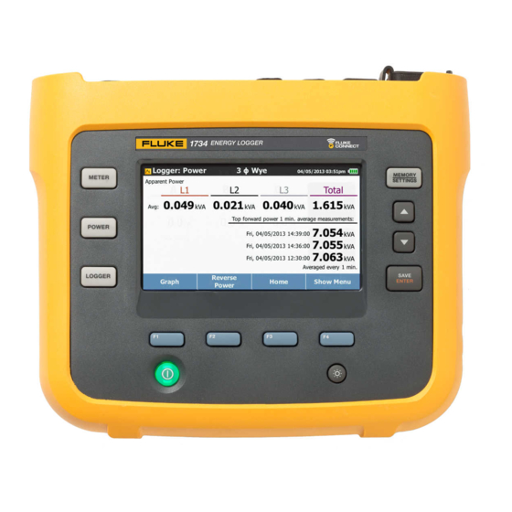
1732/1734/1736/1738/3540 FC Calibration Manual Specifications General Specifications Display ......... . 4.3-inch active matrix color TFT, 480 pixels x 272 pixels, resistive touch panel... -
Page 9: Electrical Specifications
1736/1738 ........4, mode selected automatically for attached sensor 1732/1734/3540 FC ......3, mode selected automatically for attached sensor Current Sensor Output Voltage Clamp . - Page 10 Memory Size 1732/1734/1736/1738 ......Typical 10 logging sessions of 8 weeks with 1-minute intervals and 100 events The number of actual logging sessions and logging period depends on user requirements.
- Page 11 0.1 % THD on Current ±(2.5 % + 0.05 %) 1000 % 0.1 % Voltage Harmonic 2 to 50 ±(2.5 % + 0.05 %) 1000 % 0.1 % Unbalance ±0.15 % 100 % 0.1 % [1] 1732/1734/1736/1738 only [2] 1736/1738 only...
- Page 12 1732/1734/1736/1738/3540 FC Calibration Manual Power/Energy Direct Input iFlex1500-12 iFlex3000-24 iFlex6000-36 i40S-EL Parameter Clamp: 50 mV/500 mV 150 A/1500 A 300 A/3000 A 600/6000 A 4 A/40 A Rogowski: 15 mV/150 mV Clamp: 50 W/500 W Power Range W, VA, var 150 kW/1.5 MW...
-
Page 13: Maintenance
The Logger has an internal rechargeable Lithium-ion battery. To replace the battery: Remove the Power Supply. Unscrew the four screws and remove the battery door. Replace the battery. Fasten the battery door. Caution To prevent damage to the Product, use only original Fluke batteries. -
Page 14: Replacement Parts
1732/1734/1736/1738/3540 FC Calibration Manual Replacement Parts Replacement parts and accessories are listed in Table 2. To order parts and accessories, see How to Contact Fluke. Table 2. Replacement Parts Fluke Part Ref. Description Qty. or Model Number Power Supply 4743446 ... -
Page 15: Setup
Optional: 52120A with Coils Coil 5 turns Pomona for AUX Adapter Banana-to-Pin Adapter Electronics 4690 verification [1] The 173x calibration cables and verification box are not available from Fluke. See Equipment Assembly for information on how to make these items. -
Page 16: Equipment Assembly
Calibration Manual Equipment Assembly The 173x calibration cables and verification box are not available from Fluke. If you plan to calibrate your Product rather than send it to a Fluke Service Center, use the assembly instructions that follow. 173x Calibration Cable Assembly See Table 4 for instructions on how to make the calibration cables. -
Page 17: 173X Aux Input Calibration Cable
Logger/Monitor Setup 173x AUX Input Calibration Cable See Table 5 and Figure 1 for instructions on how to make the calibration cable. Caution Cable must be marked with “max. 30 V to earth.” Any voltage-, category-, or current-ratings on safety plugs must be removed. Table 5. - Page 18 1732/1734/1736/1738/3540 FC Calibration Manual Figure 1. 173x AUX Input Calibration Cable...
-
Page 19: Verification Box Assembly
Fluke recommends using a verification box that has a divider with 30 Ω across the Logger input and 10 kΩ in series with high side of the input. See Table 6 for instructions on how to make the verification box. -
Page 20: System Requirements
Range changes in the verification can require remote commands to set the range. To communicate between the PC and the Logger, the USB driver must be installed. • 173x: the USB driver is installed when the Fluke Energy Analyze Plus (FEA+) software is installed. • 3540 FC: the USB driver is available at www.fluke.com. - Page 21 Logger/Monitor Setup Dashboard The Dashboard sheet provides all parameters at a glance that are available with the Meter and Power buttons on the instrument plus the phase angles and calculated Neutral current I . You can configure phase mapping, invert current inputs, and set the hardware range/mode of the current inputs, as well as configure the used COM port in the dashboard.
- Page 22 1732/1734/1736/1738/3540 FC Calibration Manual Phasor The Phasor sheet provides live data read-out as a phasor diagram. See Table 8. Table 8. Phasor in Excel Worksheet hcf101.eps Item Description Refresh - One time live data update.
- Page 23 Logger/Monitor Setup Calibration and Verification The Calibration and Verification sheet are the built-in procedures. See Table 9. Table 9. Calibration and Verification in Excel Worksheet Item Description hcf102.eps Verification Calibration Setup hcf103.eps Start button – When the selection window has been closed with Quit, click the Start button again to ...
-
Page 24: Basic Instrument Setup For All Verifications
Sensor selector – select items from the list for a verification of the accessory. Use DIRECT for the Fluke Logger verification. Calibration items – Select Voltage, AUX Input or Current input for calibration. For a Logger calibration all ... -
Page 25: Accuracy Verification Procedure
Logger/Monitor Accuracy Verification Procedure Accuracy Verification Procedure The procedure verifies the Power Logger accuracy at ambient temperature 23 °C ±2 °C (intrinsic error). A complete accuracy verification of the Fluke 173x consists of: • Voltage Measurement • Current Measurement •... -
Page 26: Current Measurement
1732/1734/1736/1738/3540 FC Calibration Manual Current Measurement Fluke recommends using a divider with 30 Ω across the Logger input and 10 kΩ in series with high side of the input: • Fluke PN 2114858 (10 kΩ) Fluke PN 1757740 (30 Ω) – see Table 6 for the recommended assembly of this divider. Best practice is to •... -
Page 27: Aux Input Check (1732/1734/1736/1738 Only)
Logger/Monitor Optional Verification for Flexi or Clamp (Combined Logger and Probe Specifications) AUX Input Check (1732/1734/1736/1738 Only) Connect 173x AUX input calibration cable to the Logger AUX inputs. Stack the two red banana plugs together and connect them to the calibrator Normal HI. - Page 28 1732/1734/1736/1738/3540 FC Calibration Manual Set the calibrator to source 100 V @ 57 Hz and the appropriate currents for the current probe under test. • For the 5500 Coil verification (see Table 13) when the 20 A jack column is “No” when the AUX HI connections should be used;...
- Page 29 Logger/Monitor Optional Verification for Flexi or Clamp (Combined Logger and Probe Specifications) Table 14. Clamp Current Probe Input Verification with 52120A Coil 5520A Applied Upper Lower 52120A Range Type/Range Voltage Signal Limit Limit i40S-EL, Clamp 40A HIGH 0.4 V 0.4 A 0.4108 0.3892 i40S-EL, Clamp 40A HIGH...
-
Page 30: 173X Auxiliary Input Adapter Verification (1732/1734/1736/1738 Only)
1732/1734/1736/1738/3540 FC Calibration Manual 173x Auxiliary Input Adapter Verification (1732/1734/1736/1738 Only) The Auxiliary Input Adapter has a 1000:1 divider that can be verified with a calibrator and an 8846A. To connect to the Connector pins, use a banana-to-pin adapter (Pomona Electronics 4690 is recommended). - Page 31 Logger/Monitor 173x Auxiliary Input Adapter Verification (1732/1734/1736/1738 Only) Additional Errors: Influence by galvanic connection of sources Typical additional errors for measurements on galvanic-connected sources 2x Divider Inputs Divider Input/Direct Input 2x Direct Inputs AUX1 or AUX2 AUX1 & AUX2 AUX1 or AUX2...
-
Page 32: Calibration Adjust Procedure
1732/1734/1736/1738/3540 FC Calibration Manual Calibration Adjust Procedure This procedure adjusts the Logger accuracy at ambient temperature 23 °C ±2 K (intrinsic error). The required equipment and cables for calibrating the Product are listed in Table 3. See USB Communication for instructions on how to set up the PC.
Need help?
Do you have a question about the 1732 and is the answer not in the manual?
Questions and answers