Table of Contents
Advertisement
Quick Links
Advertisement
Table of Contents

Subscribe to Our Youtube Channel
Related Manuals for Fluke 05-443


Summary of Contents for Fluke 05-443
- Page 1 05-443/05-444 Digital Wall Mount-Area Monitor Users Manual PN 4484924 Rev.1 April 2014 © 2014 Fluke Corporation. All rights reserved. Specifications are subject to change without notice. All product names are trademarks of their respective companies.
- Page 2 Fluke Biomedical warrants this instrument against defects in materials and workmanship for one year from the date of original purchase OR two years if at the end of your first year you send the instrument to a Fluke Biomedical service center for calibration. You will be charged our customary fee for such calibration. During the warranty period, we will repair or at our option replace, at no charge, a product that proves to be defective, provided you return the product, shipping prepaid, to Fluke Biomedical.
- Page 3 Fluke Biomedical, we recommend using United Parcel Service, Federal Express, or Air Parcel Post. We also recommend that you insure your shipment for its actual replacement cost. Fluke Biomedical will not be responsible for lost shipments or instruments that are received in damaged condition due to improper packaging or handling.
- Page 4 To ensure the accuracy of the Product is maintained at a high level, Fluke Biomedical recommends the product be calibrated at least once every 12 months. Calibration must be done by qualified personnel. Contact your local Fluke Biomedical representative for calibration.
-
Page 5: Table Of Contents
Dipswitch (under calibration cover) ........... 11 RS-232 Output ................... 12 9-Pin Data Connector (Female Sockets) ........... 13 Internal Detector Setups ..............13 Model 05-443 and Model 05-443-2200 ......... 13 Model 05-444 ................. 14 Common Options and Modifications............15 Time and Date Stamp Option ............15 Description .................. - Page 6 05-443/05-444 Users Manual...
- Page 7 List of Figures Figure Title Page Front Panel ....................2 Left Side-Panel ..................6 Alarm Point Notice ..................7...
- Page 8 05-443/05-444 Users Manual...
-
Page 9: Introduction
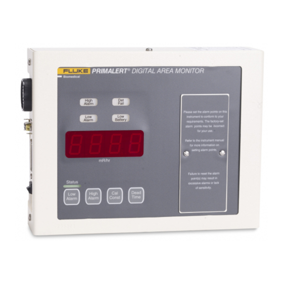
48 hours of additional use after the primary power is removed. Systems included in this manual are: • Model 05-443 and 05-443-2200 with an internal LND 71210 detector • Model 05-444 with an internal LND 71412 detector Figure shows the Product. -
Page 10: Safety Information
05-443/05-444 Users Manual huk01.eps Figure 1. Front Panel Safety Information A Warning identifies conditions and procedures that are dangerous to the user. A Caution identifies conditions and procedures that can cause damage to the Product or the equipment under test. - Page 11 • The operator or responsible body is cautioned that the protection provided by the equipment may be impaired if the equipment is used in a manner not specified by Fluke Biomedical • Only certified technician or calibration personnel should replace battery.
-
Page 12: Symbols
Linearity ..............Readings within 10 % of true value with detector connected Operating Range: 05-443 and 05-443-2200 ........1 µSv/h to 10 mSv/h (0.1 mR/hr to 1 R/hr) 05-444 ..............0.01 mSv/h to 100 mSv/h (1 mR/hr to 10 R/hr) Response .............. - Page 13 Digital Wall Mount-Area Monitor General Specifications High Voltage ............. Adjustable from 200 volts to 2500 volts Dead Time ..............Adjustable to compensate for dead time of the detector and electronics (can be read on the display) Overload ..............A display reading of -OL- and audible fail alarm indicate detector saturation.
-
Page 14: Driver Option Specification
05-443/05-444 Users Manual Driver Option Specification Power Required ............7.5 V dc at 100 mA; minimum V = 5.5 V and maximum V = 15 V Terminating Resistor ..........250 Ω Model 05-450 Recorder Output Connections (9-pin D-sub connector) Pin 5 is SIG, current output (was voltage output) -
Page 15: Radiation Units
Digital Wall Mount-Area Monitor Getting Started Read and then remove the sticker (see Figure ) from the instrument calibration cover. Checking and setting of the alarm point(s) is discussed in detail below and in the sections Setting Alarm-Points and Calibration Controls in this manual. Please set the alarm point(s) on this insturment to conform to your requirements. -
Page 16: Checking Parameters
05-443/05-444 Users Manual Checking Parameters Check the low alarm point setting by pressing the LOW ALARM button. The low alarm point will be displayed as long as the button is pressed. The low alarm point is in units of <units>. The low alarm point can be set from 0.1 <units> to 9999 <units>. -
Page 17: Operational Check (Optional)
Digital Wall Mount-Area Monitor Getting Started Operational Check (Optional) The operational check is an important assurance that the radiation detector and electronics are working correctly. Note The manufacturer of this instrument suggests that an operational check be performed on a regular basis. Local procedures may supersede this suggestion. -
Page 18: Operator Controls And Setup
05-443/05-444 Users Manual Operator Controls and Setup Calibration Controls Remove the calibration cover to expose the calibration controls. Warning To prevent possible electrical shock, fire, or personal injury: • To prevent contact with internal hazardous live parts that are accessible using a tool: turn off the Product and disconnect the power cord. -
Page 19: Dipswitch (Under Calibration Cover)
Digital Wall Mount-Area Monitor Operator Controls and Setup Dipswitch (under calibration cover) When the calibration cover is removed, a four-pole dipswitch is accessible that can activate or deactivate options. These four options are: CAL MODE, LATCH ALARM, RANGE, and SINGLE BEEP. •... -
Page 20: Rs-232 Output
2 GND pin 5 pin 7 ‘Cable connector has male pins on Model 05-443 and 05-444 side ‘Cable connector has female pins on PC side ‘open up communications with serial port #1 ‘at 2400 bps (baud), no parity, 8 data bits, 1 stop bit ‘no handshaking, buffer size of 8k... -
Page 21: 9-Pin Data Connector (Female Sockets)
The FAIL and HIGH ALARM digital signal outputs are open drain 2N7002 outputs, able to sink about 50 mA each. Internal Detector Setups Model 05-443 and Model 05-443-2200 Typical response and set points for the Product with internal energy- compensated LND 71210 G-M detector is as follows: •... -
Page 22: Model 05-444
05-443/05-444 Users Manual Model 05-444 Typical response and set points for the Product with internal energy- compensated LND 71412 G-M detector is as follows: • Operating Voltage: 550 V dc • Threshold: 100 mV dc • Calibration Constant: 150 cpm/mR/hr •... -
Page 23: Common Options And Modifications
Digital Wall Mount-Area Monitor Common Options and Modifications Common Options and Modifications Time and Date Stamp Option Description When an alarm or failure occurs, the Product will print the current reading, date, time, and either ALARM or FAIL to the RS-232 port. The instrument will print once every 30 seconds as long as the alarm or fail condition is present. -
Page 24: Calibration
05-443/05-444 Users Manual Calibration High Voltage The high voltage is adjustable from 0 V dc to 2500 V dc using the HV potentiometer located under the calibration cover. The high voltage required will depend on the type of detector used. Internal G-M detectors usually require 550 V dc. -
Page 25: Discriminator
Digital Wall Mount-Area Monitor Maintenance Discriminator The DISC potentiometer located under the calibration cover is used to set the threshold for pulses coming from the detector. The desired pulse threshold depends on the type of detector used. It is adjustable from 2.0 mV dc to 100 mV dc. -
Page 26: Recycling
05-443/05-444 Users Manual Recycling The manufacturer of this instrument supports the recycling of the electronics products it produces for the purpose of protecting the environment and to comply with all regional, national, and international agencies that promote economically and environmentally sustainable recycling systems. To this end, the... - Page 28 05-443/05-444 Users Manual...
Need help?
Do you have a question about the 05-443 and is the answer not in the manual?
Questions and answers