Sign In
Upload
Download
Table of Contents
Contents
Add to my manuals
Delete from my manuals
Share
URL of this page:
HTML Link:
Bookmark this page
Add
Manual will be automatically added to "My Manuals"
Print this page
×
Bookmark added
×
Added to my manuals
Manuals
Brands
Enterasys Manuals
Switch
08H20G4-24
Hardware installation manual
Enterasys 08H20G4-24 Hardware Installation Manual
800-series fast ethernet/gigabit ethernet switches
Hide thumbs
1
2
3
4
5
6
7
8
9
10
11
12
Table Of Contents
13
14
15
16
17
18
19
20
21
22
23
24
25
26
27
28
29
30
31
32
33
34
35
36
37
38
39
40
41
42
43
44
45
46
47
48
49
50
51
52
53
54
55
56
57
58
59
60
61
62
63
64
65
66
67
68
69
70
71
72
73
74
75
76
77
78
79
80
81
82
83
84
85
86
87
88
89
90
91
92
93
94
95
96
page
of
96
Go
/
96
Contents
Table of Contents
Troubleshooting
Bookmarks
Table of Contents
Hardware Installation Guide
Regulatory Compliance Information
Table of Contents
About this Guide
Who Should Use this Guide
How to Use this Guide
Related Documents
Conventions Used in this Guide
Getting Help
For Information about
Figure 1-1 08H20G4-24 Front Panel
Figure 1-2 08H20G4-24P Front Panel
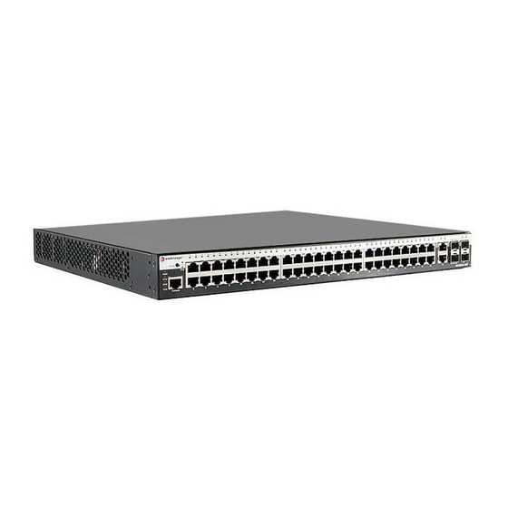
Figure 1-3 08H20G4-48 Front Panel
Figure 1-4 08H20G4-48P Front Panel
Figure 1-5 08G20G2-08 Front Panel
Figure 1-6 08G20G2-08P Front Panel
Figure 1-7 08G20G4-24 Front Panel
Figure 1-8 08G20G4-24P Front Panel
Figure 1-9 08G20G4-48 Front Panel
Figure 1-10 08G20G4-48P Front Panel
Figure 1-11 08H20G4-24 Back Panel
Figure 1-12 08H20G4-24P Back Panel
Figure 1-13 08H20G4-48 Back Panel
Figure 1-14 08H20G4-48P Back Panel
Figure 1-15 08G20G2-08 Back Panel
Figure 1-16 08G20G2-08P Back Panel
Figure 1-17 08G20G4-24 Back Panel
Figure 1-18 08G20G4-24P Back Panel
Features
Redundant Power Supply Capability
Management
Figure 1-19 08G20G4-48 Back Panel
Figure 1-20 08G20G4-48P Back Panel
Fan Operation on the 800-Series
Standards Compatibility
Chapter 1: Introduction
Overview
Table 1-1 800-Series Switch Port Types
Chapter 2 : Installation
Considerations Prior to Installation
Required Tools
Unpacking the Switch
Installing the Switch on a Flat Surface
Installing the Rubber Feet
Guidelines for Flat Surface Installation
Mounting the 24 and 48 Port Switches
Installing the Switch into a Rack
Figure 2-2 Attaching the Rackmount Brackets
Guidelines for Rackmount Installation
Mounting the 8 Port Switches
Figure 2-4 Installing a Switch in the Rack Mount Kit (08G20G2-08P Shown)
Figure 2-5 Fastening Switch(Es) to the Rack Mounting Tray (Two 08G20G2-08Ps Shown)
Figure 2-6 Positioning of Hook & Loop Straps to Secure Power Supply
Figure 2-7 Securing an Optional Redundant Power Supply to the Rack Mount Tray (Edge of Tray Position Shown)
Installing the Switch under a Table
Figure 2-9 Installing the Switch in the Table Mount Kit
Installing the Switch on a Wall
Figure 2-10 Installing the Switch on a Wall
Installing the Switch in the Lockbox and Mounting on a Wall
Figure 2-11 Installing the Switch in the 08G20G2-08 or 08G20G2-08P Lockbox Tray
Figure 2-12 Installing Optional RPS into the Lockbox Tray
Figure 2-13 Attaching a Network Cable (UTP Cable to RJ45 Port Shown)
Figure 2-14 Attaching the Wire Relief Bracket
Mounting the Lockbox on the Wall
Figure 2-15 Mounting the Lockbox over an AC Power/Data Outlet
Figure 2-16 Attaching the 08G20G2-08 and 08G20G2-08P Lockbox Cover
Connecting AC Power
Installing and Connecting a Redundant Power System
08A-Rps-150P
Table 2-1 Contents of STK-RPS-150CH2 Carton
Table 2-2 Contents of STK-RPS-150CH8 Carton
Table 2-3 Contents of 08A-RPS-150P Carton
Figure 2-17 08A-RPS-150P Installation in an STK-RPS-150CH2 Shelf
Figure 2-18 08A-RPS-150P Installation in an STK-RPS-150CH8 Shelf
Figure 2-19 Fastening the STK-RPS-150CH2 to the Rack
Figure 2-20 Fastening the STK-RPS-150CH8 to the Rack
Figure 2-21 Power Connectors on 08A-RPS-150P (Rear View)
Figure 2-22 08A-RPS-150P RPS Cable and AC Power Cord Connections
Rps-500
Connecting to the Console Port for Local Management
What Is Needed
Figure 2-26 08A-RPS-500 RPS Cable and AC Power Cord Connections
Connecting to a PC
Figure 2-27 RJ45 Connector Pinout Assignments
Figure 2-28 DB9 Console Connector Pinout Assignments
Connecting to the Web User Interface for Local Management
What Is Needed
Figure 2-29 Web Browser and Login Page
Figure 2-30 Web User Interface Main Page (08G20G4-24 Shown)
Connecting to the Network
Connecting UTP Cables to RJ45 Ports
Preparing to Install an Optional SFP Transceiver
Installing an Optional SFP Transceiver
Figure 2-32 Installing an SFP Transceiver with RJ45 Connector
Figure 2-33 Installing an SFP Transceiver with MT-RJ Connector
Removing an SFP Transceiver
Figure 2-34 Installing an SFP Transceiver with an LC Connector
Connecting Fiber-Optic Cables to SFP Ports
Completing the Installation
Initial Logon to Switch Management
Chapter 3: Troubleshooting
Checking the Leds
Figure 3-1 Switch Status Leds (08G20G4-24 Shown)
Cpu Led
Pwr Led
Table 3-1 PWR LED Definitions
Table 3-2 CPU LED Definitions
Fan Led
Link/Activity Leds
Rps Led
Table 3-3 RPS LED Definitions
Table 3-4 FAN LED Definitions
Table 3-5 Port LED Definitions for 10/100 Mbps Copper Ports
Table 3-6 Port LED Definitions for 10/100/1000 Mbps Copper Ports
Table 3-7 Port LED Definitions for 100/1000 Mbps SFP Ports
Poe LED
Table 3-8 Poe LED Definitions
Troubleshooting Checklist
Table 3-9 Troubleshooting Checklist
Removing the Switch from a Rack
Appendix A: Specifications
Switch Specifications
Table A-1 Enterasys 800-Series Switch Specifications
Redundant Power Supply Specifications
STK-RPS-150CH2 Chassis Specifications
STK-RPS-150CH8 Chassis Specifications
Table A-2 STK-RPS-150CH2 Specifications
Table A-3 STK-RPS-150CH8 Specifications
08A-RPS-150P Specifications
08A-RPS-500 Specifications
Table A-4 08A-RPS-150P Specifications
Table A-5 08A-RPS-500 Specifications
08A-RPS-24 Specifications
Table A-6 08A-RPS-24 Specifications
08A-RPS-130P Specifications
08A-RPS-150P Redundant Power Supply Connector
Figure A-1 08A-RPS-150P Power Supply Connector Pin Locations
Table A-7 08A-RPS-130P Specifications
08A-RPS-500 Redundant Power Supply Connector
Figure A-2 08A-RPS-500 Redundant Power Supply Connector Pin Locations
Table A-8 STK-RPS-150CH2 Power Supply Connector Pin Functions
Table A-9 08A-RPS-500 Redundant Power Supply Connector Pin Functions
Torque Values
Pluggable Transceiver Specifications
Console Port Pinout Assignments
Regulatory Compliance
Table A-10 Recommended Torque Values by Screw Size
Table A-11 Compliance Standards
Appendix B: Environmental Guidelines
Temperature and Humidity Guidelines
Operating Temperatures
Inlet Air Temperature Measurement
Cooling Air
Power Conditioning
Airflow Concerns for Closed Racks
Figure B-1 Closed Rack Ideal Configuration
Airflow Concerns for Open Racks
Figure B-2 Open Rack Ideal Configuration
Figure B-3 Non-Ideal Open Rack Configuration
Figure B-4 Mitigated Non-Ideal Open Rack Configuration
Dust Mitigation and Prevention
Figure B-5 Another Mitigated Non-Ideal Open Rack Configuration
Airborne Chemicals and Prevention
Table B-1 Airborne Dust Specification for Enterasys Equipment - Airborne Dust Maximum Values
Advertisement
Quick Links
1
Hardware Installation Guide
2
Management
3
Connecting to the Console Port for Local Management
4
Connecting to the Web User Interface for Local Management
Download this manual
Enterasys
800-Series
®
Fast Ethernet/Gigabit Ethernet Switches
Hardware Installation Guide
08H20G4-24, 08H20G4-24P
08H20G4-48, 08H20G4-48P
08G20G2-08, 08G20G2-08P
08G20G4-24, 08G20G4-24P
08G20G4-48, 08G20G4-48P
P/N 9034710
Table of
Contents
Previous
Page
Next
Page
1
2
3
4
5
Advertisement
Table of Contents
Troubleshooting
Chapter 3: Troubleshooting
71
Troubleshooting Checklist
76
Need help?
Do you have a question about the 08H20G4-24 and is the answer not in the manual?
Ask a question
Questions and answers
Related Manuals for Enterasys 08H20G4-24
Switch Enterasys 08G20G2-08P Hardware Installation Manual
800-series fast ethernet/gigabit ethernet switches (96 pages)
Switch Enterasys 08G20G4-24 Hardware Installation Manual
800-series fast ethernet/gigabit ethernet switches (96 pages)
Switch Enterasys 08G20G2-08 Hardware Installation Manual
800-series fast ethernet/gigabit ethernet switches (96 pages)
Switch Enterasys 08G20G4-48 Hardware Installation Manual
800-series fast ethernet/gigabit ethernet switches (96 pages)
Switch Enterasys 08G20G4-24P Hardware Installation Manual
800-series fast ethernet/gigabit ethernet switches (96 pages)
Switch Enterasys Enterasys SecureStack B2 B2G124-24 Hardware Installation Manual
Gigabit and fast ethernet switches (80 pages)
Switch Enterasys Enterasys RoamAbout RBT-1002-EU Release Notes
Roamabout wireless switch 8xx0 (28 pages)
Switch Enterasys Matrix C2 C2K122-24 Release Note
Enterasys matrix c2 c2k122-24: release note (41 pages)
Switch Enterasys Enterasys Gold Distributed Forwarding Engine 4G4282-49 Hardware Installation Manual
Enterasys networks switch hardware installation guide (90 pages)
Switch Enterasys SecureStack A2 A2H123-24 Hardware Installation Manual
Enterasys securestack a2 a2h123-24: install guide (64 pages)
Switch Enterasys SecureStack C2 C2G170-24 Hardware Installation Manual
Enterasys securestack c2 c2g170-24: install guide (74 pages)
Switch Enterasys Enterasys 6H308-48 Hardware Installation Manual
Dfe‐gold series module (90 pages)
Switch Enterasys Enterasys Gold Distributed Forwarding Engine 4H4202-72 Hardware Installation Manual
Enterasys networks switch hardware installation guide (90 pages)
Switch Enterasys SecureStack A2 A2H124-24 Datasheet
A-series fast ethernet stackable l2 switch (8 pages)
Switch Enterasys Matrix-V V2H124-24 Configuration Manual
Matrix v-series fast ethernet switch (498 pages)
Switch Enterasys B5G124-24 Hardware Installation Manual
Enterasys b5 series (78 pages)
This manual is also suitable for:
08h20g4-48p
08h20g4-48
08g20g2-08p
08h20g4-24p
08g20g4-24
08g20g2-08
...
Show all
08g20g4-48p
08g20g4-48
08g20g4-24p
Table of Contents
Print
Rename the bookmark
Delete bookmark?
Delete from my manuals?
Login
Sign In
OR
Sign in with Facebook
Sign in with Google
Upload manual
Upload from disk
Upload from URL


Need help?
Do you have a question about the 08H20G4-24 and is the answer not in the manual?
Questions and answers