
Related Manuals for Zeutschel OMNISCAN 10000 TT


Summary of Contents for Zeutschel OMNISCAN 10000 TT
-
Page 1: Installation Manual
OMNISCAN 10000 TT Installation Manual TS-0351E - 15.09.03 ZEUTSCHEL GmbH, Heerweg 2, D-72070 Tübingen-Hirschau, Germany... -
Page 2: Table Of Contents
Table of contents Table of contents PREPARATIONS ..............3 Unpacking ......................3 Components ......................3 Location ....................... 4 Required tools ..................... 4 INSTALLATION OF THE SCANNER ........5 First steps ......................5 Fixing the column....................5 Fixing the scan unit (reflector) ................6 Checking the position of the glide runners ............ -
Page 3: Preparations
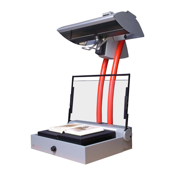
During unpacking please avoid any fingerprints or scratches on the reflector. In case you will find any dirt on the reflector (mirror), please observe the Zeutschel cleaning recommendation in the “user manual” (TS-0366E) before start cleaning. Components The delivery consists of the following components (see Fig. 1 and Fig.2): 1. -
Page 4: Location
Preparations Fig. 2 Location • Do not put the scanner under a direct source of light • Direct sun light has to be avoided • A location with indirect illumination is recommended • The table-top unit has to be put on a sturdy table Required tools •... -
Page 5: Installation Of The Scanner
Installation INSTALLATION OF THE SCANNER First steps For the installation of the OS10000 TT, at least two people are required. Do not lift up the unit by using the handle of the glass plate! Do not unscrew the screws at the column! •... -
Page 6: Fixing The Scan Unit (Reflector)
Installation Fixing the scan unit (reflector) Fig. 4 shows the drive unit before the installation of the reflector, Fig. 5 after the installation • The reflector [10] has to be installed with two persons. It should be moved over the fixing plate [11] at the drive unit [12] by turning it a little bit from front to back. -
Page 7: Checking The Position Of The Glide Runners
Installation Install the 4 nuts [15] at the threaded pins of the reflector and tighten them like • shown in Fig. 6 and Fig 7. Fig. 6 Fig. 7 Checking the position of the glide runners The glide runners [16] should glide properly down the support rails. Please check the position after each transport / installation of the scanner. -
Page 8: Connecting The Cables At The Scanner
Installation Connecting the cables at the scanner 2.5.1 SCSI cable • Connect the SCSI cable [17] to the socket of the SCSI terminator [18] at the rear left-hand side of the reflector and tighten the fixing screws manhandled (Fig.8). • Do not use a screw driver, the fixing screws might be damaged! •... -
Page 9: Control Cable (Subd) And Power Supply Cable (Amp)
Installation 2.5.2 Control cable (SubD) and power supply cable (AMP) • Plug in the white AMP plug [21] and the 25 pin SubD plug [22] at the rear right- hand side of the reflector. Tighten the fixing screws at the SubD manhandled (Fig. -
Page 10: Adjusting The Support Screw
Installation Adjusting the support screw • The support screw [25] at the back side of the column should be adjusted to avoid waggling of the book cradle on the table (Fig. 12). • After unfixing the counter nut [26] the support screw can be adjusted with a combination wrench 12mm by turning it up- or downwards. -
Page 11: Connections To The Pc
Installation Connections to the PC The scanner PC should have the following configuration: SCSI Memory Graphics adapter Controller/ (RAM) Min. Resolution Connector Pentium IV / AMD SCSI UW 512MB 16MB Athlon >1GHz 68 pin (1GB recommended) 1024x768 24bit (> 2GHz recommended) Adaptec 39320-R •... -
Page 12: Connecting The Foot Pedals
Installation Connecting the foot pedals • Connect the foot pedals “glass plate up” and “glass plate down” [29] at the rear side of the book cradle (refer to blue resp. red color margins). • To avoid unwanted disconnection of the cables, the round plugs have a thread. Please tighten them manhandled Connecting the power cords •... -
Page 13: First Start
First start FIRST START Please verify again the correct installation of the scanner hardware and the connections of the cables before starting the scanner the first time! Application hints for switching on and off the scanner • When the scanner is not operated for a longer period, you should switch off the mains switch. -
Page 14: Manufacturer And Service
Fax: + 49 – (0)7071 – 9706 44 e-mail: info@zeutschel.de http: www.zeutschel.de Service In case of confusion our troubles with our products you are welcome to get in touch with our support. Please contact your local ZEUTSCHEL dealer or the ZEUTSCHEL customer service.
Need help?
Do you have a question about the OMNISCAN 10000 TT and is the answer not in the manual?
Questions and answers