Advertisement
Quick Links
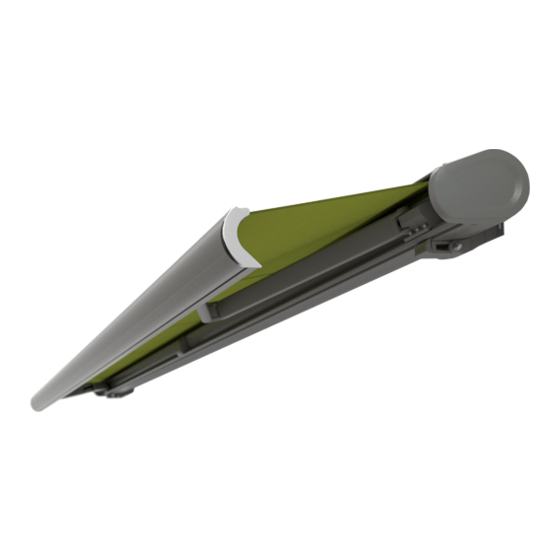
Folding-Arm Cassette Awning
markilux 6000
Fitting Instructions
1. Fitting the mounting fixtures
1.1 Fitting height
H = Projection
Y = Horizontal cover
X = Value from Table 2
K = Headroom = G – X
G = Fitting height
W° = Pitch angle
BS-Wall fixture
5 – 35°
D = 28 mm
BS-Ceiling fixture
5 – 35°
C = 30 mm
BS-Eaves fixture 5 – 35°
E = 153 mm
Table of fitting heights at a pitch angle of 5° to 35°
in
P rojection
cm
150
X
2 6
W = 5°
Y
148
X
36
W = 10°
Y
146
X
4 7
W = 15°
Y
144
X
58
W = 20°
Y
141
X
7 0
W = 25°
Y
138
X
80
W = 30°
Y
132
X
89
W = 35°
Y
126
1
BS-Wall fixture
36 – 70°
D = 16 mm
BS-Ceiling fixture
36 – 70°
C = 30 mm
BS-Eaves fixture 5 – 35°
E = 270 mm
200
250
300
350
400
28
30
32
34
36
198
248
298
348
398
43
50
57
74
81
196
246
296 346
396
59
70
81
92
103
193
242
291
340
389
74
90
106
122
138
189
237
285 333
381
89
108
127
146
165
184
230
276 316
362
103
126
149
180
205
176
220
264
308
352
116
143
170
197
224
168
210
252
294
336
Advertisement

Related Manuals for Markilux 6000


Summary of Contents for Markilux 6000
- Page 1 Folding-Arm Cassette Awning markilux 6000 Fitting Instructions 1. Fitting the mounting fixtures 1.1 Fitting height H = Projection Y = Horizontal cover X = Value from Table 2 K = Headroom = G – X G = Fitting height BS-Wall fixture BS-Wall fixture W°...
- Page 2 1.2 Face Fixture 2 Folding arms = Arm position = Fixture = Awning width = Fitting area of middle fixture (size-dependent, with 3 fixtures) Sizes in cm 3 Folding arms A and B = Arm positions = Fixture = Awning width = Fitting area of 4 fixture Sizes in cm...
- Page 3 Type of mounting A 1.2.3 Scribe the drill holes and fit fastening The distance to a possibly existent ceiling must be at fixtures with suitable fastening plates according to least 30 mm! background. Align fastening fixtures Sizes in mm horizontally! Type of mounting B With uneven facades, check the spaces with a length of cord and if necessary compensate.
- Page 4 1.3.4 Scribe the drill holes and fit fastening fixtures with suitable fastening plates according to background. Align fastening fixtures horizontally! Sizes in mm 1.4 Eaves Fixture Sizes in mm Sizes in mm 1.4.1 Determine the fitting height. Determine the position of the fixtures according to the stickers already provided (red points) on the back of the cassette (see also 1.2.1 Face Fixture).
- Page 5 1.4.2 Fasten the eaves fixture with a nail. Align the fixture horizontally with a spirit level and fix with a second nail. 1.4.3 Drill through the eaves at the screw holes. Screw fixture with suitable fastening materials. Align the fastening fixtures horizontally. 2.
- Page 6 3. Awning with motor drive The electrical connection for motor drive and/or controller connection is to be carried out as prescribed motor controller manufacturer. Modifications, particular concerning the motor, the controller and the connection lead require written authorization. The installation and setting guide is attached to the power supply cable of the motor.
- Page 7 (433 MHz): U = 230 V ~ / 290 W, 50 Hz, I = 1,25 A markilux 6000 motor drive: 3 - 4 folding arms without radio: U = 230 V ~ / 350 W, 50 Hz, I = 1,50 A 4.
- Page 8 Raise arm and relieve the load. By turning the socket head cap screw (SW 4), bring the arm to the horizontal position. Tighten socket head cap screws SW 4 (1) and SW 10 (2) on the inner bracket. 6. Fixture covers 6.1 Face fixture cover 6.1.1 From an awning pitch angle of approx.
- Page 9 6.2 Top fixture cover 6.2.1 Guide the inner side cheek of the ceiling fixture around the awning casing with a 90° turn. 6.2.2 Push outer and inner fixture cheek together. 6.2.3. Screw ceiling fixture cover to the bracket with socket head cap screw (SW 5). 7.
- Page 10 8. Awning with lighting (two lamps per unit) 8.1 Overview Lighting profile Holder Acrylic glass lighting tube colorless satin finish Fluorescent lamp Osram FQ 39 W / 827 Mask Starter casing Electrical work: Electrical installations must be carried by a qualified electrician according to VDE 0100. 8.2 Lighting with dimmer 8.2.1 The cable for the lighting connection is...
- Page 11 8.3 Lighting with On/Off switch 8.3.1 The cable for the lighting connection is marked with this sticker. The wiring diagram must definitely be observed, a faulty connection can lead to the destruction of the device! (6)=Not used! Wire color Terminal 8.3.2 For the connection of the supply and control (1) gray...
Need help?
Do you have a question about the 6000 and is the answer not in the manual?
Questions and answers