Table of Contents
Advertisement
Quick Links
Advertisement
Table of Contents

Related Manuals for Medrad Mark 7 Arterion


Summary of Contents for Medrad Mark 7 Arterion
- Page 1 Operation Manual READ BEFORE USING...
-
Page 3: Table Of Contents
5.11.2 Head Stand (KMA 320 RT) and Adjustable Height Stand (KMA 330) ............. 5 - 26 5.11.3 Mark 7 Arterion Stand Mounting Kit Configuration................5 - 27 6 Using and Understanding the Display Control Unit Screen ........6 - 29 6.1 Home Tab ............................... - Page 4 10.1 Installing the Mark 7 Arterion or Twist & Go Syringe ..................10 - 51 10.2 Filling and Purging the Mark 7 Arterion or Twist & Go Syringe ..............10 - 53 10.3 Installing and Purging Standard High Pressure Connector Tubing ............... 10 - 54 10.4 Installing and Purging Twist &...
- Page 5 10.6 Connecting to and Purging the Catheter ...................... 10 - 57 10.7 Enabling 15 mL Purge Feature and Choosing Configuration Options ............10 - 58 10.7.1 15 mL Purge ON ..........................10 - 58 10.7.2 15 mL Purge OFF..........................10 - 58 10.8 Defining a Protocol............................
- Page 6 ® MEDRAD Mark 7 Arterion Injection System 16.2 Pedestal Mount Installation ......................... 16 - 92 16.3 Power Unit Installation..........................16 - 95 16.3.1 Power Unit Connections ........................16 - 96 16.3.2 Power Unit Floor Mount Bracket Assembly..................16 - 97 16.3.3 Relocate Power Unit Connectors .......................
- Page 7 18 Options and Accessories ..................18 - 139 18.1 Mark 7 Arterion Disposables/Syringe Kits ....................18 - 139 18.2 Mark 7 Arterion System Mount Options ..................... 18 - 139 18.2.1 Injector Head Mount Options......................18 - 139 18.2.2 Power Unit Mount Options ......................18 - 139 18.2.3 Display Control Unit Mount Options ....................
- Page 8 ® MEDRAD Mark 7 Arterion Injection System...
-
Page 9: Information
Bayer HealthCare Services. 1.3 Training Information This manual is intended as an extension of the user interface of the Mark 7 Arterion Injection System to provide procedural and technical information. Additional Mark 7 Arterion training information will be available in the following formats: •... - Page 10 ® MEDRAD Mark 7 Arterion Injection System 1 - 2...
-
Page 11: About This Manual
MEDRAD Mark 7 Arterion Injection System in a safe manner. 2.1 Intended Use The MEDRAD Mark 7 Arterion Injection System is intended to be used specifically for the purposes of injecting contrast medium and common flushing solutions into humans for angiographic studies. -
Page 12: Additional Information Regarding Compliance To Iec 60601-1-2/2007
® MEDRAD Mark 7 Arterion Injection System 2.4 Additional Information Regarding Compliance to IEC 60601-1-2/2007 This section is intended to reflect conformance to IEC-60601-1-2 / 2007 3rd edition. The following statements are notices. Notices advise of circumstances that could result in damage to the device. - Page 13 About This Manual INJECTOR REQUIRES SPECIAL PRECAUTIONS REGARDING EMC. Install and put into service according to the EMC information provided below: Table 2 - 2: Guidance and manufacturer's declaration - electromagnetic emissions The injector is intended for use in the electromagnetic environment specified below. The customer or user of the injector should assure that it is used in such an environment.
- Page 14 ® MEDRAD Mark 7 Arterion Injection System Table 2 - 3: Guidance and manufacturer's declaration - electromagnetic immunity <5% UT <5% UT (>95% dip in UT) (>95% dip in UT) for 0.5 cycle for 0.5 cycle Mains power quality should be that of a...
-
Page 15: Restricted Sales
About This Manual Table 2 - 4: Guidance and manufacturer's declaration - electromagnetic immunity 800 MHz to 2.5 GHz 2.33 p Where p is the maximum output power rating of the transmitter in watts (W) according to the transmitter manufacturer and d is the recommended separation distance in meters (m). - Page 16 ® MEDRAD Mark 7 Arterion Injection System 2 - 8...
-
Page 17: Symbols And Icons
(IEC 60529). Indicates separate collection for Electrical and Electronic Equipment per Directive 2002/96/EC . Refer to the following website for additional information: http://www.medrad.com/en-us/resources/Pages/WEEE.aspx 3.3 Warnings Indicates risk of electric shock. Warning: Refer to warnings and cautions on Instructions for Use packaged in each carton. -
Page 18: Buttons And Icons
® MEDRAD Mark 7 Arterion Injection System Pushing Prohibited. Do not push at or above this point on the Injector. Air Warning Label • Air Embolism Hazard: injury or death can result. • Read operation manual. • Expel air from syringe/disposable before connecting or injecting to patient. -
Page 19: Injector Head Buttons And Icons
Symbols and Icons The On/Off Switch. The hand switch connection location found on the back of the Display Control Unit. The Power Unit cable connection location found on the back of the Display Control Unit. Indicates that an Imaging System Interface (ISI) is enabled and functioning properly. -
Page 20: Power Unit Icons
® MEDRAD Mark 7 Arterion Injection System Hand Controller. Identifies the Service Port. Pressure Jacket Syringe Alignment. 3.4.3 Power Unit Icons Power Unit On/Off switch. Indicates Alternating Current and identifies the Power Unit power cord connection. Identifies a connection for Display Control Unit1. The Power Unit has two connection points. -
Page 21: Packaging
Symbols and Icons Identifies the service port. NOTE: Used by Bayer HealthCare Services or Bayer trained personnel. Future expansion port. Future expansion port. Future expansion port. 3.5 Packaging Catalog Number Do not Re-sterilize. Do not use if package is damaged. Do Not Reuse Batch Code Date of Manufacture/Sterilization... - Page 22 ® MEDRAD Mark 7 Arterion Injection System Sterilized with Ethylene Oxide. Use By Atmospheric Pressure Limitation Chinese Recycling symbol for paperboard. Chinese Recycling symbol for corrugated cardboard. Do Not Stack Authorized Representative in the European Community. Fragile, Handle with care...
- Page 23 Symbols and Icons This Way Up Not made with natural rubber latex. 3 - 15...
- Page 24 ® MEDRAD Mark 7 Arterion Injection System 3 - 16...
-
Page 25: System Warnings, Precautions, And Notices
The system should be opened and serviced by Bayer HealthCare Services or Bayer trained service personnel. • Use only power cord approved for use on Mark 7 Arterion. • For U.S. installations, equipment shall only be connected to Hospital Grade or Hospital Only outlets. -
Page 26: Cautions
® MEDRAD Mark 7 Arterion Injection System 4.2 Cautions CAUTION Environmental Contamination Hazard - Minor or moderate patient and/ or worker injury may result. • Follow sterile technique specifically, maintain sterility of the syringe tip and plunger, syringe barrel internal surface, Quick Fill Tube, high pressure connector tubing, catheter, and Display Control Unit Sheath. -
Page 27: System Overview
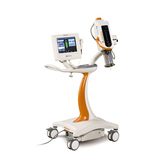
"Imaging System Interface" • "Start Switches" • "Pedestal and Stand Movement" Figure 5 - 1: Mark 7 Arterion Injection System Display Control Unit Injector Head Power Unit 5.1 Injection Protection The following means are provided to protect against over and under injections: An on-screen indication of insufficient volume is provided whenever the total volume programmed to be delivered is greater than the amount of fluid in the syringe. -
Page 28: Pressure Limiting
® MEDRAD Mark 7 Arterion Injection System 5.2 Pressure Limiting The purpose of the programmed pressure limit is to protect the patient, the catheter, and any disposable device attached to the injector. As a general rule, set pressure limit no higher than the max pressure rating of the weakest component in the fluid path (tubing, stopcocks, connectors, catheters, administration sets, etc.). -
Page 29: Technical Specifications
5.4 High Pressure Connector Tubing Specifications (Non-Twist & Go) The injection system was designed to use the MEDRAD Mark 7 Arterion Syringe and Twist and Go Syringe. When using the Mark 7 Arterion Syringe, tubing should meet the following specifications to operate in a safe and effective manner. -
Page 30: Display Control Unit
® MEDRAD Mark 7 Arterion Injection System 5.5 Display Control Unit The injection system Display Control Unit consists of a touch screen display. From the Display Control Unit, an operator can manage protocols, arm and disarm the injector, review injection history, set options, and view help topics. -
Page 31: Power Unit
5.9 MEDRAD VFlow MEDRAD VFlow (VFlow) enables the use of Variable Flow Rate injections. In the Variable Flow Rate injection mode, the injector automatically re-arms after each injection. A Variable Flow Rate injection can be initiated by the Hand Controller and ranges from 1 - 10 mL/sec in increments of 0.1 mL/sec. -
Page 32: Medrad Vflow Hand Controller
The Hand Controller button (B) is non-functional and will beep from the Injector head and DCU when depressed. Figure 5 - 5: Hand Controller NOTE: The hand controller is required to perform Variable Flow Rate injections. For installation instructions, see"10.5 - Installing the MEDRAD® VFlow Hand Controller". 5 - 24... -
Page 33: Pedestal And Stand Movement
System Overview 5.11 Pedestal and Stand Movement 5.11.1 Pedestal System Place pedestal system components into the approximate positions shown in Figure 5 - 6 prior to moving the system. When necessary, lift pedestal by using the handle to move over obstacles. Figure 5 - 6: Approximate Component Positions for System Movement 5 - 25... -
Page 34: Head Stand (Kma 320 Rt) And Adjustable Height Stand (Kma 330)
® MEDRAD Mark 7 Arterion Injection System 5.11.2 Head Stand (KMA 320 RT) and Adjustable Height Stand (KMA 330) Place hands in the positions shown in Figure 5 - 7 to move an injector Head mounted on a Head Stand and Adjustable Height Stand over obstacles. -
Page 35: Mark 7 Arterion Stand Mounting Kit Configuration
System Overview 5.11.3 Mark 7 Arterion Stand Mounting Kit Configuration Place the Mark 7 Arterion Stand Mounting Kit components into the approximate positions and place hands in the positions shown in Figure 5 - 8 prior to moving the system. - Page 36 ® MEDRAD Mark 7 Arterion Injection System 5 - 28...
-
Page 37: Using And Understanding The Display Control Unit Screen
Using and Understanding the Display Control Unit Screen The Display Control Unit touch screen has five tabs from which an operator can manage protocols, arm and disarm the injector, review injection history, set options, and view help topics. NOTE: An operator will be locked-out from a Display Control Unit if another operator is performing functions on the Injector Head or another Display Control Unit connected to the same system. -
Page 38: Actuals Window
® MEDRAD Mark 7 Arterion Injection System 6.1.2 Actuals Window The Actuals window displays Peak (maximum Flow Rate achieved), Delivered (actual total volume delivered), Total Contrast (total volume delivered for the current case), and the End Case button. An operator presses the End Case button after completing a patient procedure and before removing the disposables to retract the syringe plunger. -
Page 39: Modify Options
Used by Bayer HealthCare Services or Bayer trained personnel to Upgrade activate features. Enables Variable Flow Rate injections when this feature is activated ® MEDRAD VFlow from Upgrade. Contact Bayer to enable this feature. When VFlow is enabled, the system provides a sound when the Hand Audio Feedback Controller plunger is depressed. -
Page 40: Display Control Unit Lock-Outs
® MEDRAD Mark 7 Arterion Injection System 6.6 Display Control Unit Lock-outs The Display Control Unit will be locked-out while an operator is interacting with the Injector Head controls, or while an operator is accessing another Display Control Unit in a dual Display Control Unit system. -
Page 41: Using And Understanding The Injector Head
Using and Understanding the Injector Head This chapter describes: • "Injector Head Components" • "Injector Head Position" • "Syringe Interface" • "Pressure Jacket" • "Injector Head Displays" • "Injector Head Controls" • "Armed Light" • "Manual Knob" • "Syringe Heat Maintainer" •... -
Page 42: Injector Head Position
Mark 7 Arterion Injection System 7.2 Injector Head Position The Mark 7 Arterion Injector Head contains a sensor that monitors the head’s position: Purge (upright) (X), Intermediate (Y), or Inject (downward) (Z). The head position determines how the data displays and the available functions. -
Page 43: Piston Auto Retract
"6.4 - Options Tab" more information. 7.4 Pressure Jacket The Mark 7 Arterion has a Pressure Jacket designed to hold the syringe in place and help to maintain syringe integrity during use. Figure 7 - 3: Pressure Jacket The Pressure Jacket is manufactured from high impact resistant material; however, sharp impacts such as from dropping, may cause small barely visible cracks to form, which may propagate during subsequent pressure cycles. -
Page 44: Injector Head Displays
® MEDRAD Mark 7 Arterion Injection System 7.5 Injector Head Displays The Injector Head has two display areas. One area shows the programmed parameters for flow rate, volume, and pressure limit. The other area shows the volume remaining in the syringe. -
Page 45: Injector Head Controls
Using and Understanding the Injector Head 7.6 Injector Head Controls The Injector Head Controls on the injection head display contain the Enable button, Enable Indicator, Fill Strip, and Auto-Fill button. 7.6.1 Enable Button (F) The Enable button activates the Fill Strip and Auto-Fill button. After pressing the Enable button, the Enable Indicator (G) illuminates and the Fill Strip and Auto-Fill button stay active while in use or for five seconds of inactivity. -
Page 46: Manual Knob
® MEDRAD Mark 7 Arterion Injection System 7.8 Manual Knob Use the Manual Knob (K) to manually advance or retract the piston. Turn the knob clockwise to advance the piston and counterclockwise to retract the piston. Figure 7 - 6: Manual Knob 7.9 Syringe Heat Maintainer... -
Page 47: Power Up And Shutdown The Injector
Power Up and Shutdown the Injector This chapter describes: • "Powering up the System" • "Shutdown" 8.1 Powering up the System CAUTION Electric Shock Hazard - Minor or moderate patient and/ or worker injury may result. • Verify that the voltage and frequency marked on the serial tag on the Power Unit matches the voltage and frequency of the electrical outlet. - Page 48 ® MEDRAD Mark 7 Arterion Injection System 8 - 40...
-
Page 49: Setting And Managing Protocols
Setting and Managing Protocols Setting and Managing Protocols Over Volume Hazard - Serious patient injury or death may result. • Do not program a protocol outside of the clinically accepted volume range. • Ensure that the correct volume is programmed in the protocol for the target anatomy. Vessel Dissection Hazard - Serious patient injury or death may result. -
Page 50: Set Injection Parameters On Home Tab - Phased
® MEDRAD Mark 7 Arterion Injection System NOTE: The displayed values are based on the last used protocol or the default values. 2. Select the box corresponding to a parameter to change it. 3. Use the numeric keypad to enter the protocol parameter. -
Page 51: Set Injection Parameters On Home Tab - Variable Flow Rate
Controller. As an operator depresses the Hand Controller plunger, the system increases the Flow Rate until it reaches the maximum Flow Rate set by the operator. NOTE: If the Variable Flow Rate option is not visible, go to the Display Control Unit Options tab to enable MEDRAD VFlow. See "6.4 - Options Tab". -
Page 52: Manage Protocols From The Protocols Tab
® MEDRAD Mark 7 Arterion Injection System 9.2 Manage Protocols from the Protocols Tab NOTE: To store, view, or edit mL/m, Phased, or Variable Flow Rate protocols, enable that protocol type from the Display Control Unit Options tab. See "6.4 - Options Tab". - Page 53 Setting and Managing Protocols 9.2.1.2 Create a New Phased mL/s Protocol on the Protocols tab Phased protocols consist of multiple phases of Volumes and flow rates with a single pressure limit and rise time. NOTE: ISI does not function with Phased protocols. 1.
- Page 54 ® MEDRAD Mark 7 Arterion Injection System Figure 9 - 6: Index Number c. To enter a new phase, select an empty index number (C). A new phase is added with default values for flow rate and volume. d. Enter the phase values, as needed NOTE: The currently selected values update in the top row parameters.
-
Page 55: Recall A Stored Protocol
Setting and Managing Protocols Figure 9 - 7: Protocols Tab - Variable Flow Rate Protocols 3. Select the blank blue button (A). NOTE: If a blank button is not visible, scroll through the list of protocols until one displays. If a blank button is not available or 0 Available displays in the upper right corner, the system cannot store any more protocols. -
Page 56: Edit An Existing Protocol
® MEDRAD Mark 7 Arterion Injection System 2. Select the Type button to display the type of protocol to be recalled. 3. Select the Sort button to sort the protocols. The options are: • Sort A-Z • Sort Z-A •... -
Page 57: Delete A Protocol
Setting and Managing Protocols Figure 9 - 9: Edit Phased Protocols e. To commit the values, select a different parameter. Repeat steps b through e for each parameter to be edited. 7. To add phases: a. Select an empty index number (B) for the phase. A new phase is added with Flow Rate and Volume both equal to “1”and Flow Rate is selected. - Page 58 ® MEDRAD Mark 7 Arterion Injection System 9 - 50...
-
Page 59: Preparing For Injection
This chapter describes: • "Installing the Mark 7 Arterion or Twist & Go Syringe" • "Filling and Purging the Mark 7 Arterion or Twist & Go Syringe" • "Installing and Purging Standard High Pressure Connector Tubing" • "Installing and Purging Twist & Go HPCT"... - Page 60 ® MEDRAD Mark 7 Arterion Injection System CAUTION Environmental Contamination Hazard - Minor or moderate patient and/ or worker injury may result. • Visually inspect contents and package before use. • Do not use disposables past Use By date identified on the package.
-
Page 61: Filling And Purging The Mark 7 Arterion Or Twist & Go Syringe
Alternatively, on the Injector Head, press the Enable button and then press and release the Auto-Fill button (I). The Mark 7 Arterion fills the syringe with the preconfigured contrast volume at the preconfigured speed. The volume and speed are configured from the Display Control Unit Options tab. -
Page 62: Installing And Purging Standard High Pressure Connector Tubing
® MEDRAD Mark 7 Arterion Injection System 8. Carefully observe the FluiDots indicators to ensure that fluid is present in the syringe. Verify that the FluiDots indicators are round in the filled portion of the syringe. The rounded shape of the FluiDots indicators varies according to the type of contrast media, but an oblong shape indicates the presence of air. -
Page 63: Installing And Purging Twist & Go Hpct
Preparing for Injection NOTE: Refer to "5.4 - High Pressure Connector Tubing Specifications (Non-Twist & Go)" for high pressure connector tubing specifications. 1. Remove the Dust cap from the syringe tip if attached. 2. Insert the high pressure connector tubing into FasTurn nut (H) on the Mark 7 Arterion Syringe. -
Page 64: Installing The Medrad Vflow Hand Controller
® MEDRAD Mark 7 Arterion Injection System Figure 10 - 3: Twist & Go Connection 3. Turn the (A) Luer nut clockwise to securely tighten the high pressure connector tubing to the syringe tip (B). 4. Purge all air from the high pressure connector tubing. Turn the Manual Knob clockwise to push contrast out until all of the air bubbles have been removed from the High Pressure Connector Tube. -
Page 65: Connecting To And Purging The Catheter
Preparing for Injection 10.6 Connecting to and Purging the Catheter Air Embolism Hazard - Serious patient injury or death may result. • Advance the piston prior to connection between the high pressure connector tubing and a catheter or other non-Bayer disposables including administration sets and additions to administration sets, such as but not limited to bleed back control devices and pressure transducers. -
Page 66: Enabling 15 Ml Purge Feature And Choosing Configuration Options
® MEDRAD Mark 7 Arterion Injection System 6. Stop aspirating with manual knob once blood is visualized in the high pressure connector tubing. 7. Verify that there no air is in the high pressure connector tubing. a. If there is air in the tubing, disconnect from patient, remove air, and try fluid to fluid connection again. -
Page 67: Defining A Protocol
Preparing for Injection Table 10 - 1: 15 mL Purge Configuration Options (ON or OFF) 15 mL Purge ON 15 mL Purge OFF < ≥15 mL Plunger <15 mL Plunger ≥15 mL Plunger 15 mL Plunger Retraction Retraction Retraction Retraction MUST purge 3.5 MUST purge 3.5 mL or more ONLY... - Page 68 ® MEDRAD Mark 7 Arterion Injection System Figure 10 - 5: ISI Enabled 10 - 60...
-
Page 69: Arming And Injecting
Arming and Injecting Vessel Dissection Hazard - Serious patient injury or death may result. • Do not move injector head or pedestal while catheter is connected to patient. This chapter discusses: • "Purged Air Confirmation" • "Arming the Injector" • "Performing an Injection"... -
Page 70: Arm Single Mode
® MEDRAD Mark 7 Arterion Injection System Before an operator performs the arming process, the Sentinel window displays messages to indicate any remaining tasks that need to be performed to complete the arming process: • a syringe is present. •... - Page 71 Arming and Injecting Single mL/m and Phased protocols: select Arm (B). Figure 11 - 2: Phased protocol 3. Visually confirm that all air has been purged from the syringe and disposable set, and select Yes. NOTE: There is sufficient volume remaining in the syringe. For Single mL/s and mL/m protocols with insufficient volume remaining in the syringe for the programmed protocol, the system gives the option of overriding the programmed volume and using the available volume remaining.
-
Page 72: Arm Multi Mode
® MEDRAD Mark 7 Arterion Injection System 11.2.2 Arm Multi Mode NOTE: The term start switch in this section is used to refer to the hand switch, foot switch or hand controller. The Arm Multi mode is available only for Single mL/s and Variable Flow Rate protocols. This mode allows for multiple injections per arming sequence. -
Page 73: Performing An Injection
Injection". 11.3 Performing an Injection The Mark 7 Arterion Injection System can perform Fixed Flow Rate and Variable Flow Rate injections. For Fixed Flow Rate, Arm Single mode injections, the injector disarms after the injection is complete or an operator releases the hand switch, foot switch, or Imaging System start switch. For Fixed Flow Rate, Arm Multi mode injections and Variable Flow Rate injections, the injector remains armed until one of the disarm criteria are met. -
Page 74: Performing A Phased Injection
Imaging System to confirm its internal configuration. The tables in the subsections below show the Imaging Systems covered in this section and how each functions with the Mark 7 Arterion Injection System. NOTE: Call Bayer HealthCare Services to determine compatibility of other Imaging Systems. - Page 75 Arming and Injecting 11.3.5.1 Injection System Initiates Injection Table 11 - 1 shows the results of pressing the Mark 7 Arterion Injection System hand switch or foot switch to initiate the protocol. Table 11 - 1: Injection System Initiates Injection...
- Page 76 11.3.5.3 Injection System and Imaging System Initiate Protocol - (Philips Imaging Systems Only) Table 11 - 3 shows the results of pressing the Mark 7 Arterion Injection System hand switch or foot switch and the Philips Imaging System start switch simultaneously to initiate the protocol.
-
Page 77: Completing An Injection
Arming and Injecting Table 11 - 3: Injection System and Imaging System Initiate Protocol Bayer Catalog Number Action XMC 928A Independent Actions - See 1 knob operation Tables 10-1 and 10-2 XMC 928A Injection and X-ray 2 knob operation XMC 945 40 No Action XMC947R Independent Actions - See... -
Page 78: Refilling Syringe During A Procedure
Alternatively, on the Injector Head, press the Enable button and then press the Auto-Fill button. The Mark 7 Arterion fills the syringe with the preconfigured contrast volume at the preconfigured speed. The volume and speed are configured from the Display Control Unit Options tab. -
Page 79: Refilling Syringe With 15 Ml Purge Feature Enabled
Arming and Injecting 8. Visually confirm that all air bubbles have been removed from the syringe. Tap the pressure jacket after filling to facilitate air removal. 9. Secure the distal connector of the high pressure connector tubing. 10. Turn the Manual Knob clockwise to push contrast out until all of the air bubbles have been removed from the high pressure connector tubing. - Page 80 ® MEDRAD Mark 7 Arterion Injection System 11 - 72...
-
Page 81: Tear Down
Tear Down Biological Contamination Hazard - Serious patient and/or worker injury or death may result. • Properly discard disposables after use or if contamination may have occurred during setup or use. This chapter discusses how to tear down and immediate cleaning of the injection system. 12.1 Remove Disposables Bloodborne Contamination Hazard - Serious patient and/or worker injury or death may result. -
Page 82: Storing The Injector
® MEDRAD Mark 7 Arterion Injection System 6. Wipe components with: • a germicidal wipe, or • a bleach wipe, for isolation patients NOTE: If contrast media has leaked inside any system component, turn off the power immediately. The affected subassembly should be disassembled and cleaned by Services personnel or returned to Bayer HealthCare Services. -
Page 83: System Messages
System Messages The Mark 7 Arterion Injection System displays Sentinel Messages and Popups to alert the operator that action is required. This chapter describes: • "Error Messages" • "Sentinel Messages" • "Popup Messages" 13.1 Error Messages Electric Shock Hazard - Serious patient and/ or worker injury or death may result. - Page 84 ® MEDRAD Mark 7 Arterion Injection System Table 13 - 1: Sentinel Messages Sentinel Message Description/Resolution Use the handle and the back of the Injector Head (but not the Manual Knob or tubing) to rotate the Head in the Purge position (upward), Rotate head up and purge and purge the system of all air.
-
Page 85: Popup Messages
System Messages 13.3 Popup Messages Popups display on the touch screen and require the operator to make a selection on the screen to close the Popup. Table 13 - 2: Popup Messages Popup Message Description/Resolution The Check for Air popup displays when initially arming the injector. - Page 86 ® MEDRAD Mark 7 Arterion Injection System Table 13 - 2: Popup Messages Popup Message Description/Resolution The system was not able to achieve the programmed flow rate. System Disarmed - Pressure limit exceed. The high pressure connector tubing or catheter Check for occlusion, reduce rate or increase may be kinked limiting the flow of contrast.
- Page 87 System Messages Table 13 - 2: Popup Messages Popup Message Description/Resolution The system remained idle for 30 minutes. System Disarmed - User Inactivity Timeout. Rearm the system. ISI is not communicating correctly with the System Disarmed - ISI not ready system.
- Page 88 ® MEDRAD Mark 7 Arterion Injection System Table 13 - 2: Popup Messages Popup Message Description/Resolution Displays when an operator enters an invalid Please enter a valid month. month. Enter a valid month. Change flow mode? Select Yes to change the flow mode to mL/m.
-
Page 89: Virtualcare Option
VirtualCare Option VirtualCare is a Service expansion option that can be installed for the Mark 7 Arterion Injection System. The VirtualCare provides remote service functionality that allows Bayer HealthCare Services to remotely update injector firmware, diagnose injector errors, and retrieve logs. - Page 90 ® MEDRAD Mark 7 Arterion Injection System 14 - 82...
-
Page 91: Cleaning And Maintenance
Cleaning and Maintenance Cross Contamination Hazard - Serious patient and/or worker injury or death may result. • Do not contact disposables with cleaning agent during cleaning. • Do not conduct cleaning process during injection procedure. NOTICE Electro-Mechanical Hazard - Equipment Damage may result. •... - Page 92 ® MEDRAD Mark 7 Arterion Injection System 3. Clean the Syringe Heat Maintainer with a dampened cloth using soap and water. 4. Remove the Drop Front Cover. 5. Clean the Drop Front Cover with a soft cloth or a paper towel dampened with a cleaning solution to remove contrast media and other contamination.
-
Page 93: Inspecting The Injector Head
Cleaning and Maintenance 8. Fully advance the piston 9. Turn off the system at the Power Unit. 10. Clean the piston. 11. Clean the inner area of the syringe interface. 12. Clean the drop front. The drop front cone should pivot freely back and forth. If it does not, it may be contaminated with contrast. -
Page 94: Inspecting The Heat Maintainer
® MEDRAD Mark 7 Arterion Injection System Stress Cracks may appear after the Pressure Jacket has been subjected to a number of pressure cycles. These tiny cracks appear around the front area of the Pressure Jacket, and usually form a pattern around the jacket’s circumference. -
Page 95: Inspecting The Pedestal
Cleaning and Maintenance 15.1.7 Inspecting the Pedestal • Inspect the base, column, casters and handle for cracks and other defects that could weaken the structure • Ensure all mounting bolts and screws are secure. • Ensure that the casters roll smoothly with no binding or scraping. •... -
Page 96: Performing An Operational Checkout
® MEDRAD Mark 7 Arterion Injection System 4. Vacuum or rinse the air filter with water and thoroughly dry before re-installing. 5. Re-install the clean, dry air filter (Note the direction of arrow for air flow - air should flow into the unit). - Page 97 Cleaning and Maintenance b. Vary the position of your finger on the Fill Strip to ensure the piston load speed varies. c. Ensure that the Volume Remaining display on the head decreases. 10. Press the Enable button, and press Reverse on the Fill Strip within five seconds. a.
-
Page 98: Annually
® MEDRAD Mark 7 Arterion Injection System 18. Select either Arm Single or Arm Multiple to arm the injector. a. Press any button on the Injector Head. b. Ensure the system disarms. 19. Select either Arm Single or Arm Multiple to arm the injector. -
Page 99: Installation - System And Accessory
Installation - System and Accessory CAUTION Mechanical Hazard - Minor or moderate patient and/ or worker injury may result. • Do not create a trip hazard when routing cables. • Follow installation procedures including use of proper screws and plugging all unused holes. -
Page 100: Pedestal Mount Installation
• Do not mount DCU to Articulating Arm. The Mark 7 Arterion pedestal mount configuration ships in two boxes as noted in “Unpacking the Injection System.” The installer needs to complete the pedestal assembly, attach the Injector Head and Display Control Unit, route cables, and make the connections to the Power Unit. - Page 101 Installation - System and Accessory Figure 16 - 3: Attach Injector Head to Articulating Arm c. Secure the Injector Head by turning the Injector Head Knob as far as possible clockwise. d. Ensure that the Injector Head Knob is as tight as possible to facilitate a secure fit of the Injector Head in the Articulating Arm.
- Page 102 ® MEDRAD Mark 7 Arterion Injection System Figure 16 - 5: Insert Power Unit • Secure the Power Unit with the four thumb screws (J) attached to the base. 15. Connect Display Control Unit cord to Display Control Unit connection on the top of the Power Unit.
-
Page 103: Power Unit Installation
Electric Shock Hazard - Serious patient and/ or worker injury or death may result. • Use only power cord approved for use on Mark 7 Arterion. • For U.S installations, equipment shall only be connected to Hospital Grade or Hospital Only outlets. -
Page 104: Power Unit Connections
® MEDRAD Mark 7 Arterion Injection System 16.3.1 Power Unit Connections The Power Unit has connection ports on the top plate, front plate, and back plate. When the Power Unit ships from the factory, only the ports on the top plate and front plate have live connections. This section shows the location of each port and provides a brief description of each. -
Page 105: Power Unit Floor Mount Bracket Assembly
Installation - System and Accessory Display Control Unit Connection for a second Display Control Unit Future Expansion Port in a two Display Control Unit system Power Switch The connections on the back plate do not have live connections when the Power Unit ships from the factory. -
Page 106: Relocate Power Unit Connectors
Disconnect the power cord before removing or replacing PC boards. The Display Control Unit and Injector Head connectors on the Mark 7 Arterion Power Unit can be moved to accommodate different configurations. The Display Control Unit and Injector Head connectors found on the top of the Power Unit can be moved to the back. -
Page 107: Injector Head Mounting Options
16.4.3 Adjustable Table Bracket Installation (KMA 350) Refer to 3040373 for installation instructions. 16.4.4 Overhead Counterpoised System Installation ® For OCS installation instructions refer to the MAVIG Portegra2 Suspension System for MEDRAD Injectors Installation Manual (MED01002E). 16.5 Display Control Unit Mounting Options •... -
Page 108: Desk Stand Kit Installation
® MEDRAD Mark 7 Arterion Injection System 16.5.2 Desk Stand Kit Installation P/N 3007412 #8-32 x 5/8” Figure 16 - 15: Attach Bracket (A) to Display Control Unit Stand P/N 600-5007-400 Figure 16 - 16: Attach Rubber Feet Figure 16 - 17: Display Control Unit Back - Remove Screws Figure 16 - 18: Display Control Unit Desk Stand Attached NOTE: Reuse #8-32 1/2”... -
Page 109: Fixed Table Mount Installation
Installation - System and Accessory 16.5.3 Fixed Table Mount Installation NOTICE Electro-Mechanical Hazard - Equipment damage may result. • Before installing the Table Mount, ensure the table rail can withstand a minimum vertical static load of 18 kg (40 lbs.) Refer to the table manufacturer documentation for weight load information. - Page 110 ® MEDRAD Mark 7 Arterion Injection System Figure 16 - 20: Tightening the Clamp Knob 4. Using the 3/16” Hex Key provided, turn the adjusting screw (A) clockwise until Mounting Lever (B) contacts the bottom of the rail. Figure 16 - 21: Adjust Screw and Mounting Lever 5.
-
Page 111: Wall Mount Bracket Installation
Installation - System and Accessory 16.5.4 Wall Mount Bracket Installation NOTE: Before attaching the bracket to the wall, the installer must know if the wall studs in the room are made of metal or wood. This will determine the kind of hardware required to complete the installation. - Page 112 ® MEDRAD Mark 7 Arterion Injection System 8. Connect the cable to the rear of the Display Control Unit (a small flat head screwdriver may be required). Route the Display Control Unit cable toward the Display Control Unit wall bracket hinge.
-
Page 113: Accessory Installation
Installation - System and Accessory Figure 16 - 27: Wall Mount Friction Plate - Close-up 2. Remove the wing nut (B) from the top of the pivot bolt (A). 3. Remove the washer and spring (C). 4. Lift the mounting plate (D) off of the mounting pins and flip over. 5. -
Page 114: Syringe Pressure Jacket Installation
® MEDRAD Mark 7 Arterion Injection System Figure 16 - 29: Syringe Heat Maintainer Figure 16 - 30: Syringe Heat Maintainer Connected 16.6.2 Syringe Pressure Jacket Installation Install the Pressure Jacket on to the front of the injector prior to installing a syringe. -
Page 115: Hand Switch Mount Kit
Installation - System and Accessory Figure 16 - 32: Hand Switch Display Control Unit Location Figure 16 - 33: Use Clip to Attach Hand Switch Cable to the Display Control Unit 16.6.4 Hand Switch Mount Kit The hand switch mount kit contains hardware to allow the operator to mount the hand switch to any flat surface (such as the back of the Display Control Unit) and onto a pole or similarly shaped object. -
Page 116: Display Control Unit Sterile Sheath Installation
NOTE: Contents are sterile. Display Control Unit sheath should be applied using sterile technique. The Mark 7 Arterion Display Control Unit Sterile Sheath is intended for single patient use. 1. Use sterile technique to open the Display Control Unit Sterile Sheath package. -
Page 117: Cable Bracket Installation
NOTE: DO NOT photocopy the template as photocopying may distort the image. ALWAYS MEASURE BEFORE DRILLING. 2. Route MEDRAD Mark 7 Arterion Injection System Injector Head Extension Cable and Display Control Unit Cable through the table opening. 3. Locate the Table Cable Bracket (A). Remove the four screws (B) attaching the insert to the bracket. - Page 118 ® MEDRAD Mark 7 Arterion Injection System cient length of the Display Control Unit Cable extending beyond the opening of the bracket to connect to the Display Control Unit in the desired location. NOTE: When installing only one cable, insert the appropriate sized plug (included) into the empty hole.
- Page 119 NOTE: DO NOT photocopy the template as photocopying may distort the image. ALWAYS MEASURE BEFORE DRILLING. 2. Route Mark 7 Arterion Injection System Injector Head Extension Cable and Display Control Unit Cable through the table opening. 3. Locate the Table Cable Bracket (A). Remove the four screws (B) attaching the insert to the bracket.
- Page 120 NOTE: DO NOT photocopy the template as photocopying may distort the image. ALWAYS MEASURE BEFORE DRILLING. 2. Thread MEDRAD Mark 7 Arterion Injection System Injector Head Extension Cable and Display Control Unit Cable through the floor opening. 16 - 112...
- Page 121 Installation - System and Accessory Figure 16 - 43: Cable Routing for Extension Cables NOTE: Avoid routing extension cables with high power cables. 3. Locate the Floor Cable Bracket (A). Remove the four screws (B) attaching the insert to the bracket.
- Page 122 NOTE: DO NOT photocopy the template as photocopying may distort the image. ALWAYS MEASURE BEFORE DRILLING 2. Thread MEDRAD Mark 7 Arterion Injection System Injector Head Extension Cable and Display Control Unit Cable through the floor opening. NOTE: Avoid routing extension cables with high power cables.
- Page 123 Installation - System and Accessory Figure 16 - 47: Cable Strain Relief Removal 6. Insert the cables connectors in the corresponding sized holes in the plate. Figure 16 - 48: Removing Cable Plate NOTE: If attaching the DCU cable, remove the cover plate (C) from the plate. 7.
-
Page 124: Stand Mounting Kit Installation
16.7 Stand Mounting Kit Installation The Mark 7 Arterion Pedestal Mounting Kit is for use with the KMA 320 RT and the KMA 330. NOTE: Ensure the KMA 320 RT and KMA 330 have five (5) locking casters. If the stand does not have five locking casters, contact service for part number 699-4645-100. - Page 125 Installation - System and Accessory 5. Lock the casters on the pedestal. 6. Position Power Unit on the stand as shown below. 7. Loosely attach the Crescent Clamp (D) to the bottom half of the Tube Clamp using two 10-32 x 3/4 socket head screws (E) and 3/16 hex key.
-
Page 126: Display Control Unit (Dcu) Support Assembly Installation
® MEDRAD Mark 7 Arterion Injection System 16.9 Display Control Unit (DCU) Support Assembly Installation 1. Insert the DCU Mounting Bushing (A) into the DCU Support Post (B). 2. Align holes and secure with two 8-32 x 3/8 Phillips screws (C) using a #2 Phillips screw driver. - Page 127 Installation - System and Accessory 3. Ensure the Pedestal Arm has been rotated counterclockwise until you hit the stop. 4. Locate two DCU Mounting Bracket halves (D). 5. Orient halves together ensuring each threaded hole lines up with a through hole. 6.
- Page 128 ® MEDRAD Mark 7 Arterion Injection System 9. Insert and fasten one 1/4-20 x 1-1/4 screw (E) on the DCU Mounting Bracket into the hole closest to the DCU Support Post. 10. Rotate DCU Support Bracket so that the bracket is positioned directly under the Pedestal Arm.
-
Page 129: Specifications
Specifications This chapter lists: • "System Component Weights and Dimensions" • "Mounting Components Weights and Dimensions" • "ISI Technical Specifications" • "Environmental Specifications" 17.1 System Component Weights and Dimensions NOTE: All listed weights and dimensions are approximate. 17.1.1 Pedestal System Weight and Dimensions 47.3 in 120.1 cm 90°... -
Page 130: Display Control Unit Weight And Dimensions
® MEDRAD Mark 7 Arterion Injection System 17.1.2 Display Control Unit Weight and Dimensions 3.040 in. 7.7 cm 12.62 in. 32.1 cm 11.042 in. 28 cm Weight: 7lbs. (3.18kg) 17.1.3 Injector Head Weight and Dimensions 5.470 in. 13.9 cm 21.219 in. -
Page 131: Power Unit Weight And Dimensions
Specifications 17.1.4 Power Unit Weight and Dimensions 9.765 in. 24.8 cm 15.213 in. 4.641 in. 38.6 cm 11.8 cm 9.765 in. 24.8 cm Weight: 11 lbs. (4.99 kg) 17.2 Mounting Components Weights and Dimensions NOTE: All listed weights and dimensions are approximate. 17.2.1 Pedestal Mount Weight and Dimensions Weight*: 100 lbs. -
Page 132: Head Stand Weight And Dimensions
® MEDRAD Mark 7 Arterion Injection System 17.2.2 Head Stand Weight and Dimensions 2 in. 5.08 cm 48.5 in. 123.19 cm 35.6 in. 26.75 in. 90.42 cm 67.95 cm Weight*: 51.4 lbs. (23.32 kg) *Weight does not include the Injector Head weight. -
Page 133: Stand Mounting Kit Components Weights And Dimension
Specifications 17.2.4 Stand Mounting Kit Components Weights and Dimension. 17.2.4.1 Display Control Unit (DCU) Bracket Weight and Dimensions Weight: 4.0 lbs. (1.8 kg) *Measurements are in inches. Weight does not include DCU weight. 17.2.4.2 Power Unit Bracket Weight and Dimensions Weight: 1.2 lbs. -
Page 134: Adjustable Table Mount (Kma 350) Weight And Dimensions
® MEDRAD Mark 7 Arterion Injection System 17.2.5 Adjustable Table Mount (KMA 350) Weight and Dimensions 1.99 in. 5.1 cm 12 in. Compressed 30.5 cm 17 in. Extended 43.2 cm 5.375 in. 13.7 cm 1.44 in. 3.7 cm Weight*: 5.4 lbs. (2.44 kg) *Weight does not include the Injector Head weight. - Page 135 Specifications 17.2.6.1 Ceiling Mount Weight and Dimensions Long 39.4 in. (100.1 cm) Medium 33.5 in. (85.1 cm) Short 22.8 in. (57.9 cm) 29.5 in. 360 o 74.9 cm 360 o 35.8 in. 90.9 cm 360 o 50 o 360 o 360 o 32 in.
- Page 136 ® MEDRAD Mark 7 Arterion Injection System 17.2.6.3 Wall Mount Weight and Dimensions 70.5 in. 179 cm Required for fully extended rotation 45 ° 31.5 in. 3.5 in. 31.5 in. 80 cm 80 cm 9 cm 22 in. 56 cm 1.5 in.
-
Page 137: Fixed Table Mount Weight And Dimensions
Specifications 17.2.7 Fixed Table Mount Weight and Dimensions 1.99 in. 5.1 cm 8.06 in. 20.5 cm 5.375 in. 13.7 cm 1.438 in. 3.7 cm Weight*: 3.8 lbs (1.72 kg) *Weight does not include the Display Control Unit weight. 17.2.8 Display Control Unit Desk Stand Mount Weight and Dimensions 8.76 in. -
Page 138: Display Control Unit Wall Mount Weight And Dimensions
® MEDRAD Mark 7 Arterion Injection System 17.2.9 Display Control Unit Wall Mount Weight and Dimensions 12.56 in. 31.9 cm 11.87 in. 13.08 in. 30.1 cm 33.2 cm 1 in. 2.5 cm 1.83 in. 4.6 cm Weight*: Weight*: 4.4 lbs (1.99 kg) *Weight does not include the Display Control Unit weight. -
Page 139: Isi Technical Specifications
NOTE: Systems are configured for Universal ISI operation. If configuring for Siemens sys- tem, contact local service for assistance. 17.3.1 ISI Output Specifications The tables below list the output signals and the relay contact outputs for the Mark 7 Arterion ISI. Table 17 - 1: Output Signals Signal Name Description This signal is a pair of relay contacts output from the Injector. -
Page 140: Isi Input Specifications
Mark 7 Arterion Injection System 17.3.2 ISI Input Specifications The Mark 7 Arterion ISI is activated by a contact closure at the imaging system, and it is powered by internal 24VDC isolated supply with short circuit protection at the Mark 7 Arterion Injector. - Page 141 Arterion design and is only presented for informational purposes. Output signal to Imaging System that shorts pins 14 and 15 together as an Handswitch closed indication that the Mark 7 Arterion hand switch or foot switch is pressed. 17 - 133...
- Page 142 ® MEDRAD Mark 7 Arterion Injection System ISOLATED +24Vdc INJ_START ISOLATED RELAY GROUND ISOLATED +24Vdc INJ_DISARM ISOLATED RELAY GROUND ISOLATED +24Vdc INJ_HAND_ SWITCH_DISABLE RELAY EXTENDED_ARM RELAY INJECTING RELAY X-RAY_TRIGGER RELAY A closed relay contact INJ_HAND_SWITCH_ON indicates the corresponding signal is active...
- Page 143 Specifications INJ_START RELAY ISOLATED GROUND ISOLATED +24Vdc INJ_DISARM ISOLATED RELAY GROUND ISOLATED +24Vdc INJ_HAND_ SWITCH_DISABLE RELAY ISOLATED +24Vdc EXTENDED_ARM RELAY ISOLATED GROUND ISOLATED +24Vdc INJECTING ARMED_RETURN ISOLATED GROUND X-RAY_TRIGGER RELAY A closed relay contact indicates the corresponding INJ_HAND_SWITCH_ON signal is active RELAY Imaging System Injector Side...
-
Page 144: Environmental Specifications
® MEDRAD Mark 7 Arterion Injection System 17.4 Environmental Specifications 17.4.1 Operating The system may not meet all performance specifications if operated outside the following conditions. Temperature: +15ºC to +30º C (+59ºF to +104ºF) Humidity: 20% to 75% R.H. Air Pressure: 70 kPa to 106 kPa after it has stabilized to within the operating pressure ranges. -
Page 145: Continuous Mode Of Operation
Operation under normal load for an unlimited period, without the specified limits of temperature being exceeded. 17.4.9 EU Directive The MEDRAD Mark 7 Arterion Injection System complies with the essential requirements of the Medical Device Directive 93/42/EEC and bears the CE Mark to show conformity with the provisions of this Directive. - Page 146 ® MEDRAD Mark 7 Arterion Injection System 17 - 138...
-
Page 147: Options And Accessories
Options and Accessories The sections below list catalog numbers for: • "Mark 7 Arterion System Mount Options" • "Mark 7 Arterion Accessory Devices and Kits" • "Mark 7 Arterion Cords and Cables" • "OCS Mounting Systems" • "OEM Imaging System Interface Cables"... -
Page 148: Display Control Unit Mount Options
Description Catalog Number Floor Cable Bracket ART 700 CB F Table Cable Bracket ART 700 CB T 18.3 Mark 7 Arterion Accessory Devices and Kits 18.3.1 Switches Description Catalog Number Foot switch 25 ft. (7 m) (Optional) ART 700 FS Hand switch 6 ft. -
Page 149: Mark 7 Arterion Cords And Cables
Options and Accessories 18.4 Mark 7 Arterion Cords and Cables 18.4.1 Power Cords Description Catalog Number Power Cord - North America and Japan - Standard Length AVA 500 PC110V Power Cord - North America and Japan - 20 ft. (6 m) -
Page 150: Ocs Mounting Systems
® MEDRAD Mark 7 Arterion Injection System 18.5 OCS Mounting Systems 18.5.1 Stationary Ceiling Mount Description Catalog Number Portegra - Stationary Ceiling Mount - 22.8 in. (58 cm) Post OCS CEIL 58-P Portegra - Stationary Ceiling Mount - 33.5 in. (85 cm) Post OCS CEIL 85-P Portegra - Stationary Ceiling Mount - 39.4 in. -
Page 151: Philips
Options and Accessories 18.6.2 Philips Description Catalog Number MultiDiagnost (MD) and Integris, 15 ft. (4.5 m)-ISI, Equipotential XMC 925A Integris (Including Integris Allura), 15 ft. (4.5 m) ISI, Equipotential XMC 925A XPER, 15 ft. (4.5 m)-ISI, Power, Equipotential XMC 927A XPER, 26 ft. - Page 152 ® MEDRAD Mark 7 Arterion Injection System 18 - 144...
- Page 153 Appendix - A Cable Bracket Installation Templates TABLE MOUNT CABLE BRACKET HOLE TEMPLATE NOTE TEMPLATE MAY NOT BE TO SCALE. ALWAYS MEASURE BEFORE DRILLING. 3.70” (93.98 mm) 0.17” (4.19 mm) Through-Hole 1.0” DO NOT Photocopy. Photocopying Can Distort The Template. 3 cm 5.90”...
- Page 154 ® MEDRAD Mark 7 Arterion Injection System TABLE MOUNT CABLE INSERT HOLE TEMPLATE NOTE TEMPLATE MAY NOT BE TO SCALE. ALWAYS MEASURE BEFORE DRILLING. 2.20” (55.88 mm) 2.20” (55.88 mm) 1.10” (27.94 mm) MINIMUM MINIMUM 2.60”(66.04 mm) 0.14” (3.45 mm)
- Page 155 5.00” (127.00 mm) 0.28” (7.13 mm) 0.50” (12.70 mm) X Through-Hole 1.25” (31.80 mm) FOR CABLE CONDUIT FOR CEMENT FLOOR INSTALLATION INSTALLATION FLOOR MOUNT CABLE BRACKET HOLE TEMPLATE NOTE TEMPLATE MAY NOT BE TO SCALE. ALWAYS MEASURE BEFORE DRILLING. DO NOT Photocopy. 1.0”...
- Page 156 ® MEDRAD Mark 7 Arterion Injection System A - 148...
- Page 157 Home tab 29 Actuals window 29, 30 inspection 86 adjustable table mount installation 99 weight and dimensions 124 mounting options 99, 140 Arm Multi 64 Options tab 30 prerequisites 64 sterile sheath 22 Arm Single 62 sterile sheath installation 108 armed light 33, 37 wall mount 103 arming...
- Page 158 ® MEDRAD Mark 7 Arterion Injection System mount 107 Inject position 34 head stand Intermediate position 34 weight and dimensions 124 Purge position 34 Help tab 31 syringe interface 34 high pressure connector tubing injector storage 74 installation 54, 55...
- Page 159 Protocols tab 30 Pedestal create Phased protocol 45 cleaning 87 create Single ml/m 44 inspection 87 create Single ml/s 44 installation 92 purge weight and dimensions 123 confirmation 61 pedestal system high pressure connector tubing 55 weight and dimensions 121 purge action 61 piston syringe 53, 70...
- Page 160 ® MEDRAD Mark 7 Arterion Injection System weight and dimensions 130 weight and dimensions adjustable table mount 124 desk stand 129 Display Control Unit 122 Fixed table mount 129 head stand 124 Injector Head 122 OCS 126 Pedestal 123 pedestal system 121...
- Page 162 Bayer Medical Care Inc. Bayer, the Bayer Cross, MEDRAD, Mark 7 Arterion, MEDRAD Mark 7 Arterion, ProVis, FluiDots, MEDRAD VFlow, Twist & Go and VirtualCare may be registered trademarks of Bayer in the US and other countries.
Need help?
Do you have a question about the Mark 7 Arterion and is the answer not in the manual?
Questions and answers