Advertisement
Table of Contents
- 1 Important Safety Instructions
- 2 Mounting the Unit to the Wall
- 3 Plumbing Hook-Up
- 4 Electrical Hook-Up
- 5 Commissioning the Heater
- 6 Setting the Temperature
- 7 Basic Troubleshooting
- 8 Periodic Maintenance
- 9 Part Numbers for Fittings, Aerators and Aerator Adaptors
- 10 Repair Parts for "Thermostatic" Units
- Download this manual
INSTALLATION GUIDE AND OWNER'S
MANUAL
"SINGLE POINT", "FLOW CONTROLLED" and "THERMOSTATIC"
ELECTRIC INSTANTANEOUS WATER HEATERS
BEFORE ATTEMPTING ANY INSTALLATION, MODIFICATION OR SERVICE OF THIS
HEATER, MAKE SURE THE ELECTRICAL POWER IS DISCONNECTED.
Read and understand these instructions thoroughly before attempting the installation or service of this
water heater. Failure to follow these instructions can result in serious injury, death and/or property
damage. The warranty of this water heater will depend upon the proper installation according to these
instructions. Some heaters come supplied with separate faucet aerators. If supplied, the aerator must
be installed in the faucet for optimum performance. This heater must be used to heat water only and
be in a location where it is not subject to freezing temperatures. The manufacturer is not liable for any
damages resulting from improper installation or misuse.
This installation must conform to the latest requirements of the National Electrical Code and all
applicable state and local codes. This information is available through your local authorities. You must
understand these requirements before beginning this installation.
This unit is not required by UL 499 to have a Temperature and Pressure relief valve (T&P). You should
check with local codes to find out if one is required. If it is, it must be installed in the outlet hot water
pipe between the heater and the isolation valve.
IMPORTANT SAFETY INSTRUCTIONS
When using this electrical equipment, basic safety precautions should always be followed, including the
following:
READ AND FOLLOW ALL INSTRUCTIONS
A green terminal (or a wire connector marked "G", "GR, "Ground", or "GROUNDING") is provided within
the control box. To reduce the risk of electric shock, connect this terminal or connector to the
grounding terminal of the electric service or supply panel with a continuous copper wire in accordance
with your local electrical code.
1
Advertisement
Table of Contents

Subscribe to Our Youtube Channel
Related Manuals for EemaX SP2412


Summary of Contents for EemaX SP2412
-
Page 1: Important Safety Instructions
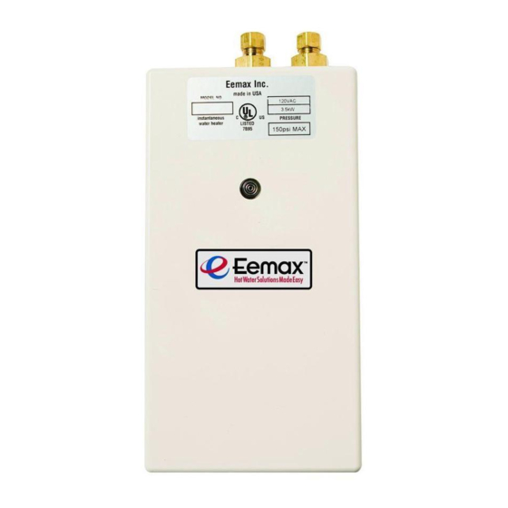
INSTALLATION GUIDE AND OWNER’S MANUAL “SINGLE POINT”, “FLOW CONTROLLED” and “THERMOSTATIC” ELECTRIC INSTANTANEOUS WATER HEATERS BEFORE ATTEMPTING ANY INSTALLATION, MODIFICATION OR SERVICE OF THIS HEATER, MAKE SURE THE ELECTRICAL POWER IS DISCONNECTED. Read and understand these instructions thoroughly before attempting the installation or service of this water heater. - Page 2 SAVE THESE INSTRUCTIONS GENERAL The Eemax “Single Point” or “SP”, “ Flow Controlled” or “EX” and “Thermostatic” or “EX-T” heaters will provide optimum performance and energy savings when located under the sink and as close as possible to the point of hot water use. For best performance the heater should be BELOW the point of use.
-
Page 3: Mounting The Unit To The Wall
This heater must be installed in a location where it is not subject to freezing temperatures. 1) MOUNTING THE UNIT TO THE WALL 1) The heater should be mounted “under the sink” as close to the point of use as possible. “Single Point”... -
Page 4: Plumbing Hook-Up
TO THE HEATER WILL RESULT. DOING THIS WILL VOID THE WARRANTY. Eemax strongly recommends that the heater be supplied directly from the main cold water line when possible. This helps to avoid a potential water flow interruption to the heater which could lead to a failure of the heating element. - Page 5 3) Remove the cover. Connect the pre-assembled inlet and outlet pipes to the heater and fully open the inlet and outlet ball valves. Check for water leaks. If a leak is at a compression fitting, slowly tighten the compression nut until it stops. Replace the cover.
-
Page 6: Electrical Hook-Up
3) ELECTRICAL HOOK-UP BEFORE BEGINNING ANY WORK ON THIS INSTALLATION, BE SURE THAT THE ELECTRICAL BREAKER IS “OFF” AND THAT ALL MOUNTING AND PLUMBING WORK HAS BEEN COMPLETED PER THESE INSTRUCTIONS. This heater must have its own independent circuit using insulated, UL listed, 2 wire cable (2 wire plus ground) of the appropriate size suitable for up to 75 degree C and protected by the correctly rated circuit breaker. - Page 7 3) Leave the breaker in the “OFF” position. Proceed to the next section: COMMISSIONING THE HEATER ELECTRICAL SPECIFICATIONS: "SINGLE "FLOW WIRE POINT" CONTROLLED" "THERMOSTATIC" SIZE MODEL MODEL MODEL VOLTS AMPS SP2412 20.0 EX2412 EX2412T 20.0 SP3012 EX3012 EX3012T 25.0 SP3512 EX3512 EX3512T 29.2 SP3208 EX3208 EX3208T 14.4...
-
Page 8: Commissioning The Heater
4) COMMISSIONING THE HEATER BEFORE SWITCHING THE ELECTRICAL BREAKER “ON”, MAKE SURE THE INLET AND OUTLET BALL VALVES ARE FULLY OPEN AND WATER IS FLOWING THROUGH THE HOT WATER FAUCET FOR A MINUTE OR TWO UNTIL THE FLOW IS CONTINUOUS AND FREE FROM AIR POCKETS. DO NOT SWITCH THE BREAKER “ON”... -
Page 9: Setting The Temperature
If water flow is TOO HOT follow the instructions below according to what model Eemax heater you have:”Single Point/Flow Controlled” or “Thermostatic”. “Single Point” and “Flow Controlled” heaters have “Thermostatic”... - Page 10 TEMPERATURE RISE AT SPECIFIED FLOW RATE, DEGREES F: "SINGLE "FLOW POINT" CONTROLLED" "THERMOSTATIC" MODEL MODEL MODEL SP2412 EX2412 EX2412T SP3012 EX3012 EX3012T SP3512 EX3512 EX3512T SP3208 EX3208 EX3208T SP4208 EX4208 EX4208T SP8208 EX8208 EX8208T SP35 EX35 EX35T SP48 EX48 EX48T...
-
Page 11: Basic Troubleshooting
The resistance varies, depending on the model of the heater, but should be less than 30 ohms. If it is much greater or fluctuating, contact Eemax for a replacement element cartridge. If you need any assistance from our Technical Service Department, make sure you can identify this water heater by having the model no:____________________ and serial number:_____________________. -
Page 12: Periodic Maintenance
If you need any assistance from our Technical Service Department, make sure you can identify this water heater by having the model no:____________________ and serial number:_____________________. 203-267-7890 800-543-6163. Call or toll free: Eemax Inc., 400 Captain Neville Drive, Waterbury, CT 06705 Tel: 800-543-6163, 203-267-7890, Fax: 203-267-7975, email: info@eemaxinc.com... - Page 13 (not available as a repair part) ELEMENT CARTRIDGE (pictured below) INSTALLS INSIDE HEATING CHAMBER “FLOW “SINGLE POINT” CONTROLLED” ELEMENT CONTROL EMERGENCY MODEL MODEL CARTRIDGE BOARD RELAY CUT OFF SP2412 EX2412 EX610 EX0183DL-30 EX250B EX278A SP3012 EX3012 EX480 EX0183DL-30 EX250B EX278A SP3512 EX3512 EX410 EX0183DL-30...
-
Page 14: Repair Parts For "Thermostatic" Units
REPAIR PARTS FOR “THERMOSTATIC” UNITS EMERGENCY CUT OFF CONTROL BOARD RELAY HEATING CHAMBER (not available as a repair part) ELEMENT CARTRIDGE (pictured below) INSTALLS INSIDE HEATING CHAMBER ELEMENT CONTROL EMERGENCY MODEL CARTRIDGE * BOARD ** RELAY CUT OFF *** EX2412T EX610 EX284-120 EX259B... - Page 15 Eemax Inc., 400 Captain Neville Drive, Waterbury, CT 06705 Tel: 800-543-6163, 203-267-7890, Fax: 203-267-7975, email: info@eemaxinc.com Eemax CE Product Plan...
- Page 16 Modules New Model No. Model Phase 240v 220v Number EC004240CE EX332T EC006240CE EX55T EC007240CE EX65T EC008240CE EX75T EC010240CE EX95T For repair parts, see pages 13 and 14. PRESSURE *Contact Eemax directly. 175 kPa min 1034 kPa max EX07200-13 Rev D...
Need help?
Do you have a question about the SP2412 and is the answer not in the manual?
Questions and answers