Table of Contents
Advertisement
Advertisement
Table of Contents

Related Manuals for Suzuki RV50


Summary of Contents for Suzuki RV50
- Page 1 :.> ••...
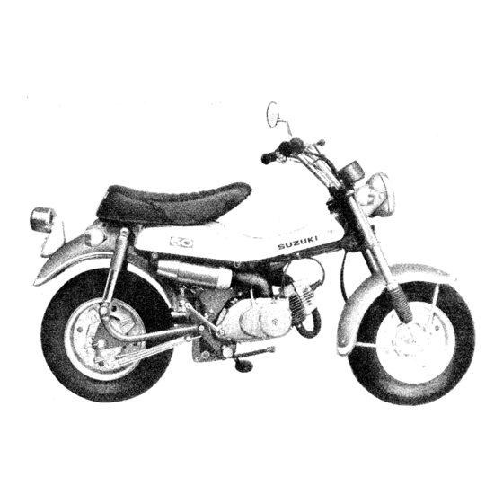
- Page 2 FOREWORD The Suzuki R V50 is a completely new fun motorcycle designed and built for on and off road use, The Suzuki R V50 has outstanding features such as reed valve type intake system and CCI lubrication system. In order to obtain good performance, many precise mechanisms are built into the machine and regular inspection and maintenance of these points are of vital importance.
- Page 3 LEFT & RIGHT SI DE VIEWS...
-
Page 4: Table Of Contents
INDEX 1. SPECIFICATIONS �{ ,�,�i _'t • • .......... . 2. PERFORMANCE CURVES .......... . GENERAL INSTRUCTIONS . Breakin g -in ............Fuel and Oil ............Genuine Parts ......................4. SPECIAL TOOLS ........... 5. NECESSARY MATERIALS Thread Lock Cement . -
Page 5: Specifications
Engine ........Suzuki CCI Lubrication system Gear-Box . - Page 6 TRANSMISSION SYSTEM Clutch Type ....... . Multi-plate, wet disc Number of Speeds .
-
Page 7: Performance Curves
2. PERFORMANCE CURVES (HP) Max. 4HP at 6,000rpm m at 5,00brpm � 0. 3 ( Gr/H � ::> 0 ..__ __ .._ __ __. _ __ __._ ___ ,... _ __ _,_ _ __ ---1 -1.-__ X 10 ENGINE REVOLUTION(R P M ) -
Page 8: General Instructions
If Suzuki CCI oil is not available, non-diluent (non self mixing type) two stroke oil, SAE # may be used . TRANSMISSION OIL ... SUZUKI TRANSMISSION * If Suzuki Transmission Oil is not available, a good quality SAE 20W/40 multi-grade motor oil should be used,... -
Page 9: Special Tools
4. SPECIAL TOOLS Special tools listed below are used to disassemble, assemble and for maintenance and service. These special tools make certain jobs easier which can not be done with ordinary tools and prevent the parts from damage. It is recommended that these special tools are purchased as shop equipment. Tool Name Ref. -
Page 11: Necessary Materials
5. NECESSARY MATERIALS RV50 requires the following material in addition to the general service equipment, tools, lubricants, cleaning solvent, every doth and so forth. For further details, refer to the pertiment items in this manual. Grease Thread Lock Cement Special grease "A" type should be used for lubrica... -
Page 12: A • A A • A A A A R A A A A A A A A A A A A A A A A A A A S A A A A A A S A
6. TROUBLESHOOTING When trouble occurs with a motorcycle, it is important to find the source of the trouble as rapidly as possible. lt is also necessary to perform only the work required to repair the machine without bothering with parts which are functioning correctly. The list of possible troubles and their causes given below should help the service man to repair motorcycles quickly without loss of effort. -
Page 13: If Abnormal Noises Are Heard In Engine
* If engine compression is low 3. Check to see that engine compression is correct 1. Cylinder and piston rings worn Repair or replace (Turn engine with kick starter). 2. Piston rings stick on piston Repair or replace 3. Cylinder head gasket damaged· Replace 4. -
Page 14: Defective Clutch
2. Check to see if engine Too high compression compression is higher 1. Carbon deposits in combustion chamber Remove carbon than standard deposit 2. Too thin a cylinder head gasket Replace 3. Check carbon deposit carbon deposit in muffler, exhaust Disassemble and pipe, exhaust port and combustion chamber remove carbon... -
Page 15: Poor Stability And Steering
1. Gear shifting shaft return spring damaged Replace Friction between gear shifting shaft Repair bent shaft and crankcase or replace 3. Jumping out of gear If the gears disengage while running 1. Gear shifting fork worn or bent Replace Gear dog teeth worn Replace gear Gear shifting cam worn or damaged Repair bent shaft or... -
Page 16: Tune-Up
7. TUNE-UP In order to maintain the full performance originally built in the motorcycle, a periodic motorcycle tune-up is essential. any deficiency is encountered during operation of the motorcycle, it must be diagnosed immediately, and rectified. Oil Pump Spark Plug Spark plug gap: Measure the gap using a thickness By turning the throttle grip, align the dent mark on the throttle valve with the upper part of the... -
Page 17: Transmission Oil
Transmission Oil Oil in the transmission deteriorates and its lubrica tion performance decreases if it is used too long. It should therefore be changed periodically. To change: 1) Remove the oil filler cap and oil drain plug located on the bottom of the engine and drain the transmission case. -
Page 18: Carburetor Throttle Cable Play
4) Finally adjust the clutch cable adjuster again .., until 3 ,.._, 5 mm (0.4 0.7 in.) of play is left at the bottom of the clutch lever. Carburetor top cover '.?> Throttle cable play rJ) Lock nut @: Throttle cable adjuster Ignition Timing Incorrect ignition timing decreases engine perform... -
Page 19: Battery
To adjust the ignition timing: 1) Remove the spark plug from the cylinder head The magneto is originally set so that the correct and screw in the dial gauge, special tool #09931 ition timing point can usually be obtained by - 00111. -
Page 20: Air Cleaner
Air Cleaner Muffler If the air cleaner is clogged with dust, the au The existence of carbon or tar in the muffler de flow is reduced causing increased fuel consumption creases exhaust efficiency, causing poor engine and a fall off in power. performance. -
Page 21: Engine
8. ENGINE The engine is made as a single-unit including the clutch and transmission and is mounted to the frame by three mounting bolts. The engine may be removed by disconnecting the wiring system, fuel system, exhaust system, air intake system and final drive system, and removing the engine mounting bolts. - Page 22 6. Removing air cleaner intake pipe 9. Disconnecting fuel and air vent hoses Required tool: Turn the fuel cock lever to the "O" position to prevent fuel flow and pull out the fuel and air vent small size hoses from the carburetor. Slacken the intake pipe clamp screw on engine side and pull out the pipe.
- Page 23 12. Removing clutch cable 15. Removing muffler Required tool: 12 mm and 14 mm 13. Disconnecting engine oil pipe Required tool: Muffler bolt small size 16. Removing drive chain Disconnect the engine oil pipe from the oil tank Required tool: outlet and block the outlet with a rubber cap.
-
Page 24: Disassembly And Assembly
Disassembly and Assembly 18. Removing pump cover This section explains the work necessary for sepa rating the crankcase, When disassembling the Required tool: engine, take the f o llowing steps. For reassembling � big size the engine after inspection or repair, f o llow the reverse order of disassembly. - Page 25 Tightening torque: 300 - 400 kg-cm ( 22 - 29 ft-lb) Hold the flywheel with the engine sprocket and heel holder and remove the rotor fixing nut. (]) Magneto stator @Neutral switch wire 6. Flattening engine sprocket washer Required tool: CD Engine sprocket and flywheel holder 4.
- Page 27 13. Removing right crankcase cover Required tool: big size and mallet or soft hammer After removing the kick starter lever, loosen the right crankcase cover fixing screws and remove the cover hitting with a mallet or a soft hammer. 16. -Removing kick starter spring Required tool: mallet or soft hammer Pull out the kick starter spring...
- Page 28 21. Removing shifting cam stop Required tool: 12mm Q) Primary pinion 19. Removing prnnary pinion lock nut Required tool: 21 mm CD Shifting earn stop (2) Shifting cam stop bolt Special tool 22. Removing gear shifting shaft #09910-20113 Place the piston holder between the connecting rod and the crankcase in order to lock the crank...
- Page 29 24. Disconnecting engine oil pipe 26. Separating c rankcase Required tool: Required tool: Tightening torque: ' ' 20 "' 30 kg-cm (1.4 - 2.2 ft-lb) Disconnect the engine oil pipes by loosening each union bolt on both sides of the crankcase respec Set the crankcase separating tool on the left crank...
- Page 30 28. Removing transmission gears Required tool: mallet or soft hammer Remove the transmission gears together with the gear shifting cam from the right crankcase. Kick starter p inion Kick starter shaft 31. Removing third drive and second driven gears Required tool: Special tool #09920-70111 Remove the snap rings with the snap ring opener...
-
Page 31: Necessary Points On Assembly
Necessary Points on Assembly This section describes tips on assembly in order to eliminate difficulties which will be encountered and the work to be done when assembling the engine. 1. Transmission and crankshaft For the installation of gears, circlips, washers and bearings, refer to the illustration. Spacer ��' Washer... - Page 32 2. Gear shifting cam 4. Crankcase To assemble the shifting forks to the gear shifting 1) Before joining the left and right crankcases, cam; clean their mating surfaces and replace the gasket with a new one. 1) Insert the short pin into the hole which is 2) The crankcase screws should be tightened ac...
- Page 33 will scraper or emery paper. This prolong life of the piston and the piston rings. The designed 1 Dowel pin chamfer is as illustrated in the fi wrong right 6. Piston The piston pin hole is off-center and the piston skirt is cut according to the shape of the scaveng...
- Page 34 3) Loosen the screws located on the engine oil outlet union bolts. 4) Supply the specified engine oil to the outlets with a oil filler as shown in the figure. Oil reservoir plate 10. Engine oil pipe When the engine assembly is completed, the oil passages have to be filled with oil.
-
Page 35: Engine Lubrication System
Engine lubrication System The engine lubrication is the Suzuki CCI system as in all other Suzuki models. The oil pump has 2 outlets connecting with respective oil feeding pipes and lubricate all the moving parts of the engine except the. - Page 36 The discharge and suction of oil in the pump take place by a change in the inside volume caused by the strokes of plunger and differential plunger. The cam fitted on tight side of the pump body is to change the travel of the plungers and is connected with the oil pump control lever which moves according to the throttle grip is fully opened and less oil is delivered when the grip is dosed.
-
Page 37: Carburetor
This carburetor incorporates not only both a main and slow system, but also a easy start system. For further details of the carburetor, please refer to the SUZUKI'S Service Manual "Carburetor and Carburetion" of 1971. - Page 38 Adjustment of carburetion Adequate carburetion is determined according to the result of various tests mainly in consideration of engine power, fuel consumption and fuel cooling effect to the engine, and jets settings are done so as to satisfy and balance all these conditions. Therefore, it is not recommended to replace the jet with other sizes than original or to change the setting position of adjustable parts except when adjusting the mixture ratio due to a different altitude or climate conditions.
-
Page 39: Kick Starter System
Adjustment of idle speed The engine idling speed may be adjusted by turning the throttle valve stop screw and pilot air adjusting screw in the following procedure. 1) Warm up the engine for about 5 minutes. 2) Screw the pilot air adjusting screw in, CD Throttle valve sto p screw 4) Open the pilot air screw gradually from its fully closed position and set it when the engine... -
Page 40: Trans Mission System
Inside the kick starter pm1on is installed a ratchet mechanism consisting of a pawl, pawl roller and pawl spring. When the kick starter lever is depressed, the kick starter shaft turns in counter-clockwise direction as seen from the lever end of the shaft. When the kick starter shaft turns counter-clockwise, the kick starter pawl clutches with the teeth machined on the inside of the kick starter pinion and the kick starter pinion turns, as the pawl moves at a right angle to it. -
Page 41: Clutch System
3rd position 1st position 2nd position 4th position Clutch System The function of the clutch is to transmit or disengage the power produced by the engine for the driving of the rear wheel through the transmission gears. The drive plates are turned by the clutch housing rotating in accordance with the engine revolutions. The driven plates are meshed in the sleeve hub on the countershaft, and are unable to transmit power in this state. -
Page 42: Air Cleaner
© ® Clutch Release Torque CD Primary gear (Z)Clutch housing � Driven plate @Pressure plate ® Clutch hub ® Clutch spring Air Cleaner The element is made of washable spongy plastics and contains oil in it so as to further prevent dust from penetration. -
Page 43: Electrical
9. ELECTRICAL Ignition System The flywheel magneto type ignition system has the electrical wiring as shown in the fi re. When the fly wheel magneto is rotated a current is generated within the primary coil mounted on the stator. With the breaker points closed the current generated in the primary coil flows to ground through the points as the primary coil is grounded, giving no influence on the primary coil in the ignition coil. -
Page 44: Battery
Battery The battery used on this model is either a YUASA or FURUKAWA made. Both are same type, 6N4-2A, and can be interchanged. Initial charge The battery is the dry-charged type unlike that of a large capacity battery, however, it must be initially charged at the specified rate before the battery is put in use since the plates may be oxidized to a certain extent during storage. -
Page 45: Body
10. BODY Front Forks illustration. The construction is shown in The front suspension is the telescopic upper bracket bolts Disassembly and assembly Required tool: 1. Removing front wheel "Front Remove the front wheel 22mm and Rear wheel" on page 46. 2. - Page 46 6. Removing stem lock nut Required tool: vV' " "' ' ' " ' tool #09940-10122 inner tube Required tool: Special tool #09920-70111 Steering stem lock nut When amount grease on the steering ball races assemble the steel balls 22 on the upper 18 on Exercise head...
-
Page 47: Front And Rear Wheel
Front and Rear Wheels The RVSO is equipped with 5.4 - 10 4PR low pressure tires. These tires are designed specifically for both off-the-road and paved road use. Disassembfy and assembfy Front wheel 1. Loosening front axfe nut Required tool: 14 m m Remove the front axle nut and pull out the axle. - Page 48 3. Removing cottepin and rear axle nut * Rear wheel Required tool: 1. Removing torque link nut Required tool: 17 mm, 22 mm and 12 mm and Tightening torque: Tightening torque: "' 430 kg-cm (20 "' 31 ft-lb) 90 ,.._, 140 kg-cm (6.6 - 1 0 ft-lb) Pull out the rear axle nut and remove the rear wheel.
-
Page 49: Rear Shock Absorber
6. When installing the front and rear wheels to the front forks and rear swinging arms, be sure to put them in correctly with the air valves faced toward the right side respectively. Rear Shock Absorber The hydraulic damper is of sealed construction and works at a damping resistance of 30 and 6 kg/0.5 m/sec in its tension and compression strokes respectively. -
Page 50: Specifications For Inspection Or Repair
11. SPECIFICATIONS FOR INSPECTION AND REPAIR Engine Part Item Standard Limit Operation Remarks below 0.03 mm Cylinder Warp on the Rectify Put emery paper on a flat surface plate head joining (0.001 in) surface and grind the head on the paper by sliding it evenly back and forth Cylinder Wear... - Page 51 Part Item Standard Limit Operation Remarks Flywheel Resistance, 2.0ft Replace Measure between magneto primary coil black colored wire and the ground when inserting a insulating material to the points. Resistance, 0.7ft Replace Measure between charging coil green colored wire and ground Condenser 0.18µF Replace...
-
Page 52: Body
Body Part Item Standard Limit Operation Remarks Brake Wear Front & Rear Replace Measur,e the diam- 106mm shoe eter when the shoes (4.17 in) are installed in place Wear Brake Front & Rear Front & Rear Replace drum 110mm 110.7 mm (4.33 in) (4.36 in) Drive... -
Page 53: Tightening Torque
12. TIGHTENING TORQUE Tightening torque Part kg-cm lb-ft 26 ""38 "' Front axle nut 50 ,..._. 80 3.6 '""'5.8 Front brake cam lever bolt 200 ,.._, 300 Front fork upper bracket fixing bolts 8.7 ,..._. 14 "' . Handlebar clamp bolts 200 ,..._. - Page 56 EXPLODED VIEW OF ENGINE...
- Page 57 PERIODIC INSPECTION LIST The chart below indicates time when inspections, adjust1nents and maintenance arc required based on the distance the motorcycle runs, that is initia1 1.000 km (750 mi), and every 3,000 km (2,000 mi), 6,000 km (4,000 mi) and 12,000 km (8,000 mi) thereafter. According to the chart, advise users to have the motorcycle checked and serviced at your shop.
-
Page 58: Wiring Diagram
8. WIRING DIAGRAM Turn signal r� Right rear turn Right front turn signallarnp signal lamp (6V8W) (6V BWI Fuse {15A) Turn signal indicator lamp {6V 1.7W) Tail/Brake lamp 16V 3/lOW) Lehraartum signal lamp ... Chargingcoil (6V SW) � IG ..Ignition ... - Page 59 SUZUKI fla111amats11-Nisl1i P,0.Box J H<JJ11,mi. l fs", J"t"m © 11-1978 9'73 Printed iri Jap,m...
Need help?
Do you have a question about the RV50 and is the answer not in the manual?
Questions and answers