
Related Manuals for JB-Lighting Varyscan 4 1200 HMI


Summary of Contents for JB-Lighting Varyscan 4 1200 HMI
- Page 1 Varyscan* 4 1200 HMI Made in Germany by JB-lighting JB lighting Lichtanlagentechnik GmbH Sallersteigweg 15, 89134 Blaustein, Tel. +49 7304 9617-0, Fax. -99...
- Page 2 Varyscan* 4 1200 HMI Bedienungsanleitung deutsch Seite 05-38...
- Page 3 Varyscan* 4 1200 HMI Operating Instructions english Page 39-70...
- Page 4 Varyscan* 4 1200 HMI Bedienungsanleitung...
- Page 5 Varyscan* 4 1200 HMI Varyscan* 4 1200 HMI Made in Germany by JB-lighting Version 1.1 Vorwort Sie haben sich für den Kauf des Varyscan* 4 1200 HMI von JB-lighting entschieden. Vielen Dank für das entgegengebrachte Vertrauen.
- Page 6 Der Varyscan* 4 1200 HMI gibt Ihnen viele Möglichkeiten, Ihre gewünschten Effekte zu realisieren. Lesen Sie zuerst in aller Ruhe diese Bedienungsanleitung durch, denn sie enthält Informationen, die Ihnen gewährleisten, Ihren Varyscan* voll zu nutzen. Viel Spaß und gute Shows wünscht Ihnen JB-lighting Inhaltsverzeichnis Bedienungsanleitung Deckblatt...
-
Page 7: Table Of Contents
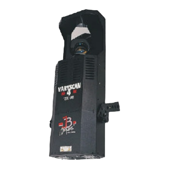
Varyscan* 4 1200 HMI Abbildung Varyscan* 1200 HMI Rückansicht und Lage der Bedienelemente Auspacken der Varyscan* Anlage Brenner einsetzen / auswechseln Inbetriebnahme der Anlage DIP-Schaltereinstellungen Betriebsartenwahl DMX-Adresseneinstellung Eine bestimmte DMX-Adresse einstellen Auswechseln der Gobos GOBO Maße B Serviceanleitung Fehlerbehebung Abgleichen des Spiegelanschlages Einstellen der "Motorbremse"... -
Page 8: Rückansicht Und Lage Der Bedienelemente
Varyscan* 4 1200 HMI Rückansicht und Lage der Bedienelemente... -
Page 9: Auspacken Der Varyscan* Anlage
Varyscan* 4 1200 HMI Belegung der DMX-Buchsen DMX-Eingang DMX-Ausgang Pin Nr. Signal Kabelfarbe Pin Nr. Signal Kabelfarbe Ground schwarz Ground schwarz DMX - weiß DMX - weiß DMX + DMX + frei frei gr/sw frei Auspacken der Varyscan* Anlage Vor Ihnen befindet sich die komplette Varyscan*-Anlage. -
Page 10: Brenner Einsetzen/Auswechseln
Varyscan* 4 1200 HMI Entnehmen Sie zuerst alle Teile aus den Kartons. • Varyscan* 1200 HMI • diese Anleitung Prüfen Sie, ob alle Teile in der Lieferung enthalten sind. Sollten Sie einen Transportschaden feststellen oder sollten Sie feststellen, daß Teile fehlen, teilen Sie dies bitte sofort dem Transportunternehmen bzw. - Page 11 Varyscan* 4 1200 HMI 2. Varyscan* einstellen Alle Spots sollten im selben Winkel hängen, das heißt der gedachte Winkel zwischen Lot und Varyscan* sollte bei allen Varyscan* gleich sein. 3. Varyscan* verkabeln Spannungsversorgung: Lassen Sie von einem Fachmann an das offene Ende des Anschlußkabels einen Schuko- Stecker anbringen, oder lassen Sie das Kabel direkt an 230 Volt 50 Herz anschließen.
-
Page 12: Betriebsartenwahl
Schalter 1 auf off, so haben Sie nur Voll- bzw. Halbfarben. Betriebsartenwahl: DIP-Schalter Nr.2 Schalter 2 und 3 Es stehen Ihnen insgesamt 3 DMX-Kanal-Formate zur Verfügung, die im folgenden genauer erklärt werden (Kurzbeschreibung siehe Typenschild). 1. JB-lighting 8 Kanal Kanal 1 X-Achse Kanal 2... - Page 13 Varyscan* 4 1200 HMI 3. JB-lighting 6 Kanal Kanal 1 X-Motor Kanal 2 Y-Motor Kanal 3 Gobo Kanal 4 Farbe Kanal 5 Dimmer/Shutter Kanal 6 Iris / Gobodreh DIP-Schaltereinstellung: DIP-Schalter Nr.2 Schalter 2 und 3 on Reset über DMX: DIP-Schalter Nr.2 Schalter 4 Wenn Sie an Ihren Varyscan* von Ihrem DMX-Pult aus einen Reset durchführen wollen, so...
- Page 14 Varyscan* 4 1200 HMI Varyscan* Nr. DMX-Adresse Schaltereinstellung...
- Page 15 Varyscan* 4 1200 HMI In der 8-Kanal-Betriebsart müssen die Adressen in 8er-Schritten eingestellt werden. Varyscan* Nr. DMX-Adresse Schaltereinstellung Varyscan* Nr. DMX-Adresse Schaltereinstellung...
- Page 16 Varyscan* 4 1200 HMI Bestimmung der DIP-Schaltereinstellung für bestimmte DMX-Adressen Die einzelnen DIP-Schalter entsprechen den oben angezeigten Werten. Soll nun eine bestimmte DMX-Adresse eingestellt werden, so muß diese nur aus den einzelnen Werten zusammengezählt werden. Beispiel: DMX-Adresse "45" 32 + 8 + 4 + 1 = 45 SW6 SW4 SW3 SW1 Die restlichen DIP-Schalter SW9 SW8 SW7 SW5 SW2 bleiben auf "OFF".
-
Page 17: Auswechseln Der Gobos
Varyscan* 4 1200 HMI Auswechseln der Gobos Öffnen Sie den Deckel mit der Beschriftung Varyscan* 4 1200 HMI, indem Sie die sechs Kreuzschlitzschrauben herausdrehen. Jetzt können Sie die Gobos am Goborad aus der Halterung drücken und die neuen Gobos einsetzen. Achten Sie darauf, daß das Gobo exact mit den Schlitzen in der Halterung einrastet. -
Page 18: B Serviceanleitung
Varyscan* 4 1200 HMI 2. Standardformat: (M-Size) Außendurchmesser: 66,0 mm Nutzdurchmesser: 49,0 mm B Serviceanleitung Fehlerbehebung Fehler Behebung des Problems Das Gerät arbeitet überhaupt nicht 16 Ampere-Sicherung des Gerätes (kein Lüftergeräusch zu hören) austauschen (Skizze Seite 5) Der Brenner des Gerätes leuchtet nicht, aber 1. -
Page 19: Einstellen Der "Motorbremse
Varyscan* 4 1200 HMI Um den Spiegel an Ihrem Varyscan* 1200 HMI abzugleichen, gehen Sie wie folgt vor: Stellen DIP-Schalter Initialisierungsmodus (DIP-Schalterstellung siehe Seite 7) und schalten Sie Ihren Varyscan* ein. Warten nun, Scanner seine Initialisierung durchlaufen hat und alle Motoren stehen. -
Page 20: Allgemeine Information Zum Dmx512 Protokoll
Varyscan* 4 1200 HMI Achtung: Vergessen Sie nicht beim Abschluß Ihrer Wartungsarbeiten die Einschübe wieder zu verriegeln, indem Sie die silbernen Schrauben wieder vorsichtig hineindrehen. 1. Reinigung aller optischen Teile: Sie sollten in regelmäßigen Abständen die optischen Teile des Varyscan* reinigen, um wieder die maximale Helligkeit des Scanners herzustellen. -
Page 21: Kanalbelegung Varyscan* 4 1200 Hmi
Varyscan* 4 1200 HMI Kanal 5 Shutter / Dimmer Kanal 6 Iris / Gobopositionierung / Goborotation Damit nun nicht jedes angeschlossene DMX-Gerät die gleichen Funktionen ausführt, werden die Geräte hintereinander adressiert; d.h. das Erste verwendet die ersten sechs Adressen (gilt für ein Gerät mit sechs Kanälen) und das Zweite verwendet die nächsten sechs Adressen (Gerät mit sechs Kanälen) der 512 DMX-Adressen (Beispiel Varyscan* siehe Seite 10). - Page 22 Varyscan* 4 1200 HMI Farbe 6 DMX 048 - 055 Farbe 7 DMX 056 - 063 Farbe 8 DMX 064 - 071 Farbe 9 DMX 072 - 079 Farbe 10 DMX 080 - 087 Farbe 11 DMX 088 - 095 Farbe 12 DMX 096 - 103 Farbe 13...
- Page 23 Varyscan* 4 1200 HMI Shuttersequenz 8,65 Blitze/sec Shuttersequenz 9,25 Blitze/sec Shuttersequenz 10,0 Blitze/sec Shutter offen DMX 244 - 255 Kanal 6 = Iris Iris (linear) DMX 000 - 255 Kanal 7 = drehbare Gobos (Positionierung und Rotation) 0° 180° 360° 540°...
- Page 24 Varyscan* 4 1200 HMI rechts Dreh langsamste Geschwindigkeit rechts Dreh höchste Geschwindigkeit Kanal 2 = Farbe Farbe 0 (weiß) DMX 000 - 007 Farbe 1 DMX 008 - 015 Farbe 2 DMX 016 - 023 Farbe 3 DMX 024 - 031 Farbe 4 DMX 032 - 039 Farbe 5...
- Page 25 Varyscan* 4 1200 HMI Gobo 4 Tageslichtfilter DMX 234 - 246 Gobo 4 Prisma DMX 247 - 255 wenn am DIP-Schalter Nr. 2 Schalter 4 auf "ON" GOBO 4 Prisma DMX 247 - 254 Reset Kanal 4 = Dimmer und Shutter Shutter Dimmer zu -->...
- Page 26 Varyscan* 4 1200 HMI Kanal 6 = y (tilt) 90 Grad 3. JB lighting 6 Kanäle Kanal 1 X-Achse Kanal 2 Y-Achse Kanal 3 Gobo und Effektrad Kanal 4 Farbe Kanal 5 Dimmer / Shutter Kanal 6 Iris und Gobodreh Kanal 1 = x (pan) 170 Grad Kanal 2 = y (tilt) 90 Grad Kanal 3 = Gobo und Effektrad...
- Page 27 Varyscan* 4 1200 HMI Kanal 4 = Farbe Farbe 0 (weiß) DMX 000 - 007 Farbe 1 DMX 008 - 015 Farbe 2 DMX 016 - 023 Farbe 3 DMX 024 - 031 Farbe 4 DMX 032 - 039 Farbe 5 DMX 040 - 047 Farbe 6 DMX 048 - 055...
-
Page 28: Belegung Dmx-In / Dmx-Out
Varyscan* 4 1200 HMI Shuttersequenz 4,00 Blitze/sec Shuttersequenz 4,65 Blitze/sec Shuttersequenz 4,88 Blitze/sec Shuttersequenz 5,26 Blitze/sec Shuttersequenz 5,88 Blitze/sec Shuttersequenz 6,25 Blitze/sec Shuttersequenz 6,90 Blitze/sec Shuttersequenz 7,14 Blitze/sec Shuttersequenz 7,30 Blitze/sec Shuttersequenz 7,40 Blitze/sec Shuttersequenz 8,00 Blitze/sec Shuttersequenz 8,65 Blitze/sec Shuttersequenz 9,25 Blitze/sec Shuttersequenz 10,0 Blitze/sec Shutter offen... -
Page 29: Technische Daten
Varyscan* 4 1200 HMI Lage der Buchsen siehe Seite 5 DMX-IN DMX-OUT Pin1: Ground schwarz Pin1: Ground schwarz Pin2: DMX- beige Pin2: DMX- beige Pin3: DMX+ Pin3: DMX+ Pin4: frei Pin4: frei Pin5: + 5V grün Pin5: frei Technische Daten Ausmaße: Höhe 100cm... -
Page 30: Belegung Der Steckerleisten Und Jumper
Varyscan* 4 1200 HMI Belegung der Steckerleisten und Jumper... - Page 31 Varyscan* 4 1200 HMI Farbe Farbe Pin Farbe Farbe Stecker X-Motor blau grün gelb Y-Motor blau weiß gelb Effektrad blau grün gelb Farbrad blau grün gelb Shutter/Dim.1 blau orange gelb Shutter/Dim.2 blau orange gelb Goborad blau grün gelb Gobodreh blau grün gelb Iris...
- Page 32 Varyscan* 4 1200 HMI 0,6W 0,6W 9*10K Sip 0,25W 240R 0,6W 9*10K Sip 0,25W 120R 0,6W 0,6W 0,6W 0,6W 0,6W 0,6W 240R 0,6W 2,2K 0,6W 120R 0,6W 0,6W 1,2R 1,2R 1,2R 0,6W 0,6W 1,2R 0,6W 0,6W 240R 0,6W 1,5R 120R 0,6W 0,6W 0,6W...
- Page 33 Varyscan* 4 1200 HMI 22uF 470uF 100n 100nF 100nF 47uF 820pF 220nF 820pF 47uF 47uF 220nF 220nF 47uF 220nF 220nF 47uF 4700uF 220nF 4700uF 220nF 4700uF 100nF 47uF 3,3nF 220nF 220nF 2,2nf 47uF 47uF 220nF 220nF 47uF 47uF 820pF 220nF 820pF 47uF 3,3nF...
- Page 34 Varyscan* 4 1200 HMI PBL3771 Treiber X-Motor PBM3960 PBL3771 Treiber Y-Motor PBM3960 TCA3727 Treiber Gobodreh 74HC574 74HC574 74HC574 TCA3727 Treiber Iris TCA3727 Treiber Gobo LM317 TCA3727 Treiber Farbrad TCA3727 Treiber Effektrad 74HC574 74HC574 74HC574 TCA3727 Treiber Shuttermotor1 74HC574 74HC574 TCA3727 Treiber Shuttermotor2 Quarz 16MHz SW DIP-10...
-
Page 35: Bestückungsplan
Varyscan* 4 1200 HMI Bestückungsplan Platine Varyscan* 4 1200 HMI... - Page 36 Varyscan* 4 1200 HMI...
- Page 37 Varyscan* 4 1200 HMI Operating Instructions...
- Page 38 Varyscan* 4 1200 HMI Varyscan* 4 1200 HMI Made in Germany by JB-lighting Version 1.1 Preface You decided to buy a Varyscan* 4 1200 HMI by JB-lighting.
- Page 39 With the Varyscan* 4 1200 HMI you have many facilities to realize desired effects. First of all read through the operating instructions very calmly, because they contain informations that will guarantee an entire use of your Varyscan*. We wish you lots of fun and successful shows. JB-lighting Index A Operating instructions Slip...
- Page 40 Varyscan* 4 1200 HMI Preface Index Illustration of Varyscan*1200 HMI Backview and position of operating sections Unpacking of Varyscan* equipment How to put in/ exchange the bulb Starting the equipment DIP-switch positions Optional drive modes Adjustment of DMX-addresses Adjustment of a definite DMX-address Changing of gobos Gobo measurements B Service instructions...
- Page 41 Varyscan* 4 1200 HMI...
- Page 42 Varyscan* 4 1200 HMI Back view and position of operating sections Occupation of DMX-sockets DMX-in DMX-out Pin No. signal Colour of wire Pin No. Signal Colour of wire Ground black Ground black DMX - white DMX - white DMX + DMX + frei not connected...
- Page 43 Varyscan* 4 1200 HMI Before you, you find the complete Varyscan*equipment. First of all, take all parts from the carton. Varyscan* 1200 HMI these operating instructions Check, if the delivery contains all parts. Should you notice a damage through transportation, please immediately inform the carriers respectively your dealer.
- Page 44 Varyscan* 4 1200 HMI To scoop the optimal functioning of your Varyscan*, you should hang up the spots as high as possible. 2. Adjustment of Varyscan* All spots should hang in the same angle, i.e. the imagined angle between perpendicular and Varyscan* should be the same among all Varyscans* 3.
- Page 45 Varyscan* 4 1200 HMI Infinitely Variable Colour Changing: DIP-switch No.2 switch 1 i.e. the moment this function is turned on, every DMX-factor between 0 and 128 corresponds to an adjustment of the colour wheel. You can produce not only half colours but 1/3- 2/3 colours or 1/4- 3/4 colours etc.
-
Page 46: Jb Lighting 8 Channel Drive Mode Channel
Varyscan* 4 1200 HMI DIP-switch position: DIP-switch No.2 switch 2 off, switch 3 on 3. JB lighting 6 channel drive mode channel 1 x-motor channel 2 y-motor channel 3 gobo channel 4 colour channel 5 dimmer/shutter channel 6 iris/gobo rotation DIP-switch position: DIP-switch No.2 switch 2 and 3 on Reset on DMX: DIP-switch No.2 switch 4 If you would like to reset your Varyscan* from your DMX-desk, turn switch 4 on at DIP-switch... - Page 47 Varyscan* 4 1200 HMI Varyscan* No. DMX-address DIP-switch position...
- Page 48 Varyscan* 4 1200 HMI In 8 channel drive mode addresses have to be adjusted in 8 steps. Varyscan* No. DMX-address DIP-switch position Varyscan* No. DMX-address DIP-switch position...
- Page 49 Varyscan* 4 1200 HMI Definition of DIP-switch positions for defined DMX-addresses Every single DIP-switch responds to the above designated figures. If you would like to adjust a defined DMX-address, you have to add up the single figures to get it. For example: DMX-address "45"...
- Page 50 Varyscan* 4 1200 HMI All remaining DIP-switches SW9 SW8 SW7 SW5 SW2 stay in position "OFF". Changing of gobos Open the lid with the label Varyscan* 4 1200 HMI, by screwing off the six screws. Now you are able to press the gobos at the gobo wheel out of their holder and then put in other gobos. Take care that the gobo engages exactly with it's slits in the holder.
- Page 51 Varyscan* 4 1200 HMI 1. Gobos JB-size Outside diameter: 68,0 mm Use diameter: 49,0 mm 2. Standard size (M-size) Outside diameter: 66,0 mm Use diameter: 49,0 mm B Service instructions Repair of defects Defect Reparation The appliance does not work at all (you Exchange 12 Ampere fuse of the can not hear any noise from the appliance...
- Page 52 Varyscan* 4 1200 HMI The bulb of the appliance does not 1. The bulb is defect, you have to shine, but electronics are working, i.e. change it motors are working 2. The temperature switch of the appliance is released. Plug out your Varyscan* and after approximately 15 minutes plug it in again.
- Page 53 Varyscan* 4 1200 HMI Part no. 5 has to be pushed on the axis of the stepping-motor until the parts no. 2 can not be compressed anymore. After remove the part no. 5 about 0,5 mm. After turn the fastening screws.
-
Page 54: Channel 6 Iris
Varyscan* 4 1200 HMI Attention: Do not use too much oil! General Informations about DMX512 Record DMX512 record is devided in 512 addresses. You have 512 addresses to your disposal. To be able to connect different appliances with a DMX-controller, it is necessary to determine the number of DMX-channels for every appliance. - Page 55 Varyscan* 4 1200 HMI channel 3 = gobo gobo 0 (Beam) DMX 000 - 031 gobo 1 DMX 032 - 063 gobo 2 DMX 064 - 095 gobo 3 DMX 096 - 127 gobo 4 DMX 128 - 255 if at DIP-switch No.2 switch 4 is "ON" gobo 4 DMX 128 - 254...
-
Page 56: Iris And Gobo Rotation
Varyscan* 4 1200 HMI shutter sequence 2,27 flashes/sec shutter sequence 2,50 flashes/sec shutter sequence 2,70 flashes/sec shutter sequence 3,10 flashes/sec shutter sequence 3,50 flashes/sec shutter sequence 3,63 flashes/sec shutter sequence 4,00 flashes/sec shutter sequence 4,65 flashes/sec shutter sequence 4,88 flashes/sec shutter sequence 5,26 flashes/sec shutter sequence 5,88 flashes/sec shutter sequence 6,25 flashes/sec... -
Page 57: Gobo And Effect Wheel
Varyscan* 4 1200 HMI channel 2 colour channel 3 gobo and effect wheel channel 4 dimmer / shutter channel 5 X-axis channel 6 Y-axis channel 1 = iris and gobo rotation iris closed / gobo first position iris open / gobo first position - 64 second gobo position third gobo position... - Page 58 Varyscan* 4 1200 HMI daylight filter 20 - 29 prism 30 - 39 floodfilter 40 - 51 gobo 1 white 52 - 64 gobo 1 artificial light filter 65 - 77 gobo 1 daylight filter 78 - 90 gobo 1 prism 91 - 103 gobo 2 white DMX 104 - 116...
- Page 59 Varyscan* 4 1200 HMI shutter sequence 4,00 flashes/sec shutter sequence 4,65 flashes/sec shutter sequence 4,88 flashes/sec shutter sequence 5,26 flashes/sec shutter sequence 5,88 flashes/sec shutter sequence 6,25 flashes/sec shutter sequence 6,90 flashes/sec shutter sequence 7,14 flashes/sec shutter sequence 7,30 flashes/sec shutter sequence 7,40 flashes/sec shutter sequence 8,00 flashes/sec shutter sequence 8,65 flashes/sec...
- Page 60 Varyscan* 4 1200 HMI gobo 3 artificial light filter DMX 169 - 181 gobo 3 daylight filter DMX 182 - 194 gobo 3 prism DMX 195 - 207 gobo 4 white DMX 208 - 220 gobo 4 artificial light filter DMX 221 - 233 gobo 4 daylight filter DMX 234 - 246...
- Page 61 Varyscan* 4 1200 HMI shutter sequence 1,23 flashes/sec shutter sequence 1,33 flashes/sec shutter sequence 1,43 flashes/sec shutter sequence 1,52 flashes/sec shutter sequence 1,60 flashes/sec shutter sequence 1,67 flashes/sec shutter sequence 1,77 flashes/sec shutter sequence 1,85 flashes/sec shutter sequence 1,96 flashes/sec shutter sequence 2,17 flashes/sec shutter sequence 2,27 flashes/sec shutter sequence 2,50 flashes/sec...
- Page 62 Varyscan* 4 1200 HMI Occupation DMX-In / DMX-Out Position of sockets see page 5 DMX-IN DMX-OUT Pin1: ground black Pin1: ground black Pin2: DMX- beige Pin2: DMX- beige Pin3: DMX+ Pin3: DMX+ Pin4: frei Pin4: frei Pin5: + 5V green Pin5: frei Technical data...
- Page 63 Varyscan* 4 1200 HMI (The inlet of the Eprom has to point to the same direction as the inlet of the IC-holder.) Close the lid and fix it with screws. Plug in your Varyscan* and please test all functions. Plan of current circuits for Varyscan* 4 1200HMI...
- Page 64 Varyscan* 4 1200 HMI Occupation of connectors and Jumper...
- Page 65 Varyscan* 4 1200 HMI colour colour Pin colour colour connector x-motor blue green yellow y-motor blue white yellow effect wheel blue green yellow colour wheel blue green yellow shutter/dim.1 blue orange yellow shutter/dim.2 blue orange yellow gobo wheel blue green yellow gobo rotation blue...
- Page 66 Varyscan* 4 1200 HMI 0,6W 0,6W 9*10K Sip 0,25W 240R 0,6W 9*10K Sip 0,25W 120R 0,6W 0,6W 0,6W 0,6W 0,6W 0,6W 240R 0,6W 2,2K 0,6W 120R 0,6W 0,6W 1,2R 1,2R 1,2R 0,6W 0,6W 1,2R 0,6W 0,6W 240R 0,6W 1,5R 120R 0,6W 0,6W 0,6W...
- Page 67 Varyscan* 4 1200 HMI 22uF 470uF 100n 100nF 100nF 47uF 820pF 220nF 820pF 47uF 47uF 220nF 220nF 47uF 220nF 220nF 47uF 4700uF 220nF 4700uF 220nF 4700uF 100nF 47uF 3,3nF 220nF 220nF 2,2nf 47uF 47uF 220nF 220nF 47uF 47uF 820pF 220nF 820pF 47uF 3,3nF...
- Page 68 Varyscan* 4 1200 HMI PBL3771 driver x-motor PBM3960 PBL3771 driver y-motor PBM3960 TCA3727 driver for goborotation 74HC574 74HC574 74HC574 TCA3727 driver for iris TCA3727 driver for gobowheel LM317 TCA3727 driver for colour wheel TCA3727 driver for effect wheel 74HC574 74HC574 74HC574 TCA3727 driver for shutter motor 1...
- Page 69 Varyscan* 4 1200 HMI Plan of electronic parts for electronic board of Varyscan* 4 1200 HMI...
Need help?
Do you have a question about the Varyscan 4 1200 HMI and is the answer not in the manual?
Questions and answers