Table of Contents
Advertisement
Advertisement
Table of Contents

Related Manuals for Aruba 7010 Series


Summary of Contents for Aruba 7010 Series
- Page 1 Aruba 7010 Series Controller...
- Page 2 Legal Notice The use of Aruba Networks, Inc. switching platforms and software, by all individuals or corporations, to terminate other vendors’ VPN client devices constitutes complete acceptance of liability by that individual or corporation for this action and indemnifies, in full, Aruba Networks, Inc.
-
Page 3: Table Of Contents
Connecting an LC Fiber Optic Cable ............23 Specifications, Safety, and Compliance..........25 7010 Specifications .....................25 Physical ......................25 Power Supply Specifications ................25 Operating Specifications................25 Storage Specifications ..................25 Safety and Regulatory Compliance ..............25 FCC .......................25 Aruba 7010 Mobility Controller | Installation Guide... - Page 4 Industry Canada....................25 EU Regulatory Conformance ................26 Battery Statements ..................26 Proper Disposal of Aruba Equipment ..............26 Waste of Electrical and Electronic Equipment ..........26 European Union RoHS ..................26 China RoHS ....................27 Aruba 7010 Mobility Controller | Installation Guide...
-
Page 5: Preface
Preface This document describes the hardware features of the Aruba 7010 Controller. It provides a detailed overview of the physical and performance characteristics of each controller model and explains how to install the controller and its accessories. Guide Overview Chapter 1, “7010 Controller” on page 7 provides a detailed hardware overview of the 7010 controller and ... -
Page 6: Contacting Support
Wireless Security Incident arubanetworks.com/support/wsirt.php Response Team (WSIRT) Support Email Addresses Americas and APAC support@arubanetworks.com EMEA emea_support@arubanetworks.com WSIRT Email wsirt@arubanetworks.com Please email details of any security problem found in an Aruba product. | Preface Aruba 7010 Mobility Controller | Installation Guide... -
Page 7: 7010 Controller
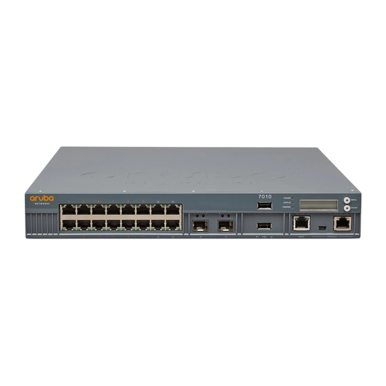
The Aruba 7010 Controller is a wireless LAN controller that connects, controls, and intelligently integrates wireless Access Points (APs) and Air Monitors (AMs) into a wired LAN system. The 7010 series includes the following two models and they do not differ physically or functionally from each other: 7010-US: For the United States of America ... -
Page 8: 7010 Components
Item Quantity Aruba Document Pointer (Printed) Optional accessories are available for use with the Aruba 7010 controllerand are sold separately. Contact your Aruba sales representative for details and assistance. 7010 Components This section introduces the component and its location in the Aruba 7010 controller. -
Page 9: Access Ports (Ethernet Ports)
PoE power (150W) available in the chassis. In the Aruba 7010 controller, the access ports 0 to 11 that support PoE/PoE+ are numbered in orange and the access ports 12 to 15 that do not support PoE are numbered in gray. -
Page 10: Uplink Ports
Green (Solid) 1000 Mbps 10/100 Mbps Uplink Ports The Aruba 7010 controller includes two 1000BASE-X uplink ports (16 and 17). See Figure 4. It is recommended to use Aruba supported SFP transceivers in these ports. Figure 4 Ports, LEDs, and LCD Panel... -
Page 11: Power, Status, And Peered Leds
Aruba tests and supports Aruba optics within their controller systems. Third party optics are not tested or supported; therefore, Aruba does not guarantee proper functionality of third party optics when used in an Aruba system. Each uplink port has two LEDs. These LEDs are used to monitor the status and activity on each port. -
Page 12: Lcd Panel
LCD Panel The Aruba 7010 controller is equipped with an LCD panel (see Figure 4 on page 10.) that displays information about the controller’s status and provides a menu that allows basic operations such as initial setup and reboot. The LCD panel displays two lines of text with a maximum of 16 characters on each line. -
Page 13: Usb Interface
1000Mbps 10/100Mbps Mini USB Console Connector The Aruba 7010 controller is equipped with one Mini USB (type B) connector that provides console access for direct local access. See Figure 4 on page 10. If both Mini USB and RJ-45 Console ports are connected, the Mini USB connection takes precedence over the RJ-45 Console connection. -
Page 14: Console Port
Mini USB Driver To use the Mini USB console port, you must install the Aruba Mini USB driver on the computer that will manage your controller. To download the driver, perform the following steps: 1. Go to https://support.arubanetworks.com. 2. Click on the Tools & Resources tab. -
Page 15: Power Supply
Aruba tests and supports Aruba approved optics within their controller devices. Non-approved third party optics are not tested or supported; therefore, Aruba does not guarantee proper functionality of non-approved third party optics when used in an Aruba system. For a complete list of Aruba approved optics, contact your Aruba sales representative. - Page 16 | 7010 Controller Aruba 7010 Mobility Controller | Installation Guide...
-
Page 17: Installation
“Installing an SFP” on page 22 Please only use the included or Aruba specified cables, power cords, AC power supplies, and batteries. The power cord should not be used with other electric equipment than what is specified by Aruba. 接続ケーブル、電源コード、AC アダプタ、バッテリーなどの部品は、必ず添付品または指定品をご使用ください。... -
Page 18: Selecting A Location
Some racks require screws that differ from those included with the 7010 controller. Ensure that you have the correct screws before installing the 7010 controller. Installation Steps To install a 7010 controller into a two-post 19-inch Telco rack: | Installation Aruba 7010 Mobility Controller | Installation Guide... - Page 19 Leave a minimum of 10 cm (4 inches) of space on the left and right side of the controller for proper air flow and ventilation. Leave additional space in the front and the back of the controller to access network cables, LED status indicators, and power cord. Aruba 7010 Mobility Controller | Installation Guide Installation |...
-
Page 20: Required Tools And Equipment
1. Fasten the mounting brackets over the mounting holes on the sides of the 7010 controller using the eight screws for mounting bracket (four per bracket) and a suitable screwdriver (see Figure 10). | Installation Aruba 7010 Mobility Controller | Installation Guide... - Page 21 3. Create the holes and insert wall anchors if your installation requires them. 4. Align the mounting bracket holes with the holes you created in the wall (see Figure 11). Figure 11 Wall Mounting 5. Use appropriate screws to secure the 7010 controller. Aruba 7010 Mobility Controller | Installation Guide Installation |...
-
Page 22: Connecting And Disconnecting The Ac Power Cord
1. Slide the SFP module, top side facing upward, into a 1000Base-X port until a connection is made and an audible click is heard (see Figure 12). Figure 12 Installing an SFP | Installation Aruba 7010 Mobility Controller | Installation Guide... -
Page 23: Removing An Sfp
To disconnect an LC fiber optic cable from an SFP-SX or SFP-LX module: 1. Depress the transceiver handle to release the latch on the cable and simultaneously pull the cable out of the port. Figure 13 Connecting an LC Fiber Optic Cable Aruba 7010 Mobility Controller | Installation Guide Installation |... - Page 24 | Installation Aruba 7010 Mobility Controller | Installation Guide...
-
Page 25: Specifications, Safety, And Compliance
Aruba controllers must be installed by a professional installer. The professional installer is responsible for ensuring that grounding is available and it meets applicable local and national electrical codes. This device complies with Part 15 of the FCC Rules. Operation is subject to the following two conditions: (1) this device may not cause harmful interference, and (2) this device must accept any interference received, including interference that may cause undesired operation.”... -
Page 26: Eu Regulatory Conformance
Proper Disposal of Aruba Equipment Waste of Electrical and Electronic Equipment Aruba products at end of life are subject to separate collection and treatment in the EU Member States, Norway, and Switzerland and therefore are marked with the symbol shown at the left (crossed-out wheelie bin). The treatment applied at end of life of these... -
Page 27: China Rohs
RoHS Directive are Lead (including Solder used in printed circuit assemblies), Cadmium, Mercury, Hexavalent Chromium, and Bromine. Some Aruba products are subject to the exemptions listed in RoHS Directive Annex 7 (Lead in solder used in printed circuit assemblies). - Page 28 | Specifications, Safety, and Compliance Aruba 7010 Mobility Controller | Installation Guide...
Need help?
Do you have a question about the 7010 Series and is the answer not in the manual?
Questions and answers