
Related Manuals for Daikin EUWAC8FZW1


Summary of Contents for Daikin EUWAC8FZW1
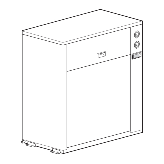
- Page 1 INSTALLATION AND OPERATION MANUAL Packaged air-cooled water chillers EUWAC5FZW1 EUWAC8FZW1 EUWAC10FZW1...
- Page 2 1 3 3 EUWAC5FZ (mm) 1345 EUWAC8FZ (mm) 1290 1125 1122 EUWAC10FZ (mm) 1395 1101 1275 1083 1272 5 0 0 2 0 0 2 5 0 8 0 0 2 0 0...
- Page 3 3PW14788-1C...
-
Page 4: Table Of Contents
The EUWAC packaged air-cooled water chillers can be combined Operating the unit ................5 with Daikin fan coil units or air handling units for air conditioning pur- poses.They can also be used for supplying water for process cooling. Introduction ..................5 The present installation chapter describes the procedures for Description .................. -
Page 5: Options And Features
Options and features ELECTION OF LOCATION The EUWAC unit should be installed in a location that meets the Options following requirements: Glycol application for chilled water temperature down to –10 The foundation is strong enough to support the weight of the unit or –5°C. -
Page 6: Important Information Regarding The Refrigerant Used
Provide adequate safeguards in the water circuit to make sure Ensure that a protective guard is installed in front of that the water pressure will never exceed the maximum the air outlet to prevent that the fan blades be allowable working pressure. touched. -
Page 7: Piping Insulation
NOTE Provide adequate safeguards in the water circuit to Switch off the main isolator switch before making any make sure that the water pressure will never exceed connections (switch off the circuit breaker and remove or the maximum allowable working pressure. switch off the fuses). -
Page 8: Operating The Unit
In case of persisting problems contact your local Daikin Dealer. Condenser The function of the condenser is to change the state of the Before starting up the unit for the first time, make sure that... -
Page 9: Safety Devices
Safety devices Internal wiring - Parts table In its standard version, the unit is equipped with the following safety Refer to the internal wiring diagram sticker on the unit. devices: The abbreviations used are listed below: A1P ....PCB: Terminal unit Overcurrent relay (general safety device) The overcurrent relay (K4S) is located in the switch box of the A2P .... -
Page 10: Before Operation
Refrigerant leak Check the inside of the unit on refrigerant leakage. If there is a PERATION refrigerant leak, call your local Daikin dealer. Oil leak The EUWAC units are equipped with a digital controller offering a user-friendly way to set up, use and maintain the unit. -
Page 11: Digital Controller
Z key, to scroll through the list of direct or user parameters or to on the fan housing. If they run in the wrong direction, call your lower a setting. local Daikin dealer. LEDs provided on the controller: Abnormal noise and vibrations... - Page 12 Water leaks In the first case, the controller saves the changes, leaves the list of direct parameters and returns to its normal operation, Check the evaporator and the external water circuit on water displaying the inlet water temperature. leaks. In the second case the display starts flashing. Approximately Drain disposal 40 seconds later, the controller leaves the list of direct Put the service covers in place so that the unit is completely...
-
Page 13: Advanced Features Of The Digital Controller
Advanced features of the digital controller ei,e0 : indicates that the supply voltage is exceedingly low (EU) or exceedingly high (EO). In these cases contact a licensed This chapter gives an overview of the direct parameters and user electrician, parameters provided by the controller. In the following chapter, you fl : indicates that there was no water flow either during the will learn how you can set up and configure the EUWAC unit using period of 15 seconds after the pump was started or for 5... - Page 14 To define the cooling temperature difference, proceed as follows: In the second case, the display starts flashing. Approximately 40 seconds later, the controller leaves the list of user Enter the list of direct parameters. parameters without saving the modifications. The inlet water temperature reappears on the display.
- Page 15 In the second case, the display starts flashing. Approximately Defining the timer threshold for maintenance warning 40 seconds later, the controller leaves the list of user parameters without saving the modifications. The inlet water User parameter cb allows you to define a timer threshold (running temperature reappears on the display.
-
Page 16: Troubleshooting
Resetting the timers. Before contacting your local Daikin dealer, read this chapter carefully, When user parameter h9 is set to 1, the above-described advanced it will save you time and money. - Page 17 The cooling capacity of the unit is too been changed, it is possible that the ually towards the factory setting until circuit is too high. low. Call your local Daikin dealer. used pulley setting with lower airflow the problem is solved. Water flow is too high.
-
Page 18: Maintenance
“Switching the EUWAC unit on”. Compressor Check on oil leaks. If there is an oil leak, call your local Daikin dealer. Check for abnormal noises and vibrations. If the compressor is damaged, call your local Daikin dealer. Installation and operation manual... - Page 19 NNEX NNEX Saturated temperature Calculation of external pressure drop The figures below represent the average saturated temperature of 5 Hp 8 Hp 10 Hp R407C in relation to the pressure readout. General specifications High pressure side Nominal air flow /min) long side W 1102 (mm)
- Page 20 NNEX Fan characteristics The figures below represent the external static pressure of the unit (ESP) in function of the air flow of the fans (AF). EUWAC5FZ EUWAC10FZ Values are applicable only in case the fanspeed controller is not Values are applicable only in case the head pressure switch for actived.
- Page 21 S1HP S4LP θ > P> P< θ < M11F M11F EUWAC5 EUWAC8+10...
- Page 22 4PW14037-1D...
Need help?
Do you have a question about the EUWAC8FZW1 and is the answer not in the manual?
Questions and answers