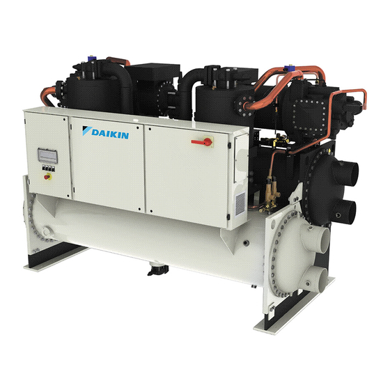
Summary of Contents for Daikin EWWD370H-XS
- Page 1 Installation, Operation and Maintenance Manual D – EIMWC00311-11EN Original instructions Water-cooled screw chillers EWWD370H-XS ~ EWWDC12H-XS Refrigerant: R-134a D – EIMWC00311-11EN - 1/12...
- Page 2 Typical refrigerant single circuit – Condenser and evaporator water inlet and outlet are indicative. Please refer to the machine dimensional diagrams for exact water connections. D – EIMWC00311-11EN - 2/12...
- Page 3 Typical refrigerant double circuit – Condenser and evaporator water inlet and outlet are indicative. Please refer to the machine dimensional diagrams for exact water connections D – EIMWC00311-11EN - 3/12...
- Page 4 Legend Compressor Oil Separator Discharge shut off valve Check valve Condenser Liquid line isolating valve Liquid and humidity indicator Electronic expansion valve Evaporator Suction shut off valve (optional) Strainer Solenoid valve Shut off valve Jet pump Shut off valve Solenoid valve Liquid and humidity indicator Solenoid valve...
- Page 5 This manual is an important supporting document for qualified personnel but it is not intended to replace such personnel. Thank you for purchasing this chiller The purpose of this manual is to allow the installer and the qualified operator to ensure proper installation, commissioning READ THIS MANUAL...
-
Page 6: Label Identification
Figure 1 - Description of the labels applied to the electrical panel Single circuit unit Label Identification 1 – Unit nameplate data 6 – Non flammable gas symbol 2 – Lifting instructions 7 – Refrigerant type 3 – Open the valve on the oil separator 8 –... - Page 7 Figure 2 - OPERATION RANGE Unit with option 'high temperature kit' Standard unit Operation with glycol Part Load Operation only Evaporator Leaving Water Temp. (°C) Safety In case of sudden stop of the unit, follow the instructions on the Control Panel Operating Manual which is part of the on- The machine must be firmly secured to the ground.
- Page 8 The unit must be lifted with the utmost attention and care tubes of the condenser and evaporator are expanded inside following lifting label instructions; lift unit very slowly, keeping it the tube plate to allow the replacement, if necessary. The perfectly level.
- Page 9 If the unit is installed in places that are easily accessible to Installing the flow switch people and animals, it is advisable to install protection grids To ensure sufficient water flow through the evaporator, it is around the unit. essential that a flow switch be installed on the water circuit. To ensure best performance on the installation site, the The flow switch can be installed either on the inlet or outlet following precautions and instructions must be followed:...
- Page 10 listed in this manual and with good practice of machines ATTENTION maintenance. Before starting the compressors, it is imperative that the We strongly advise stipulating a maintenance contract with a discharge shut-off valve after the oil separators is fully service authorized by the manufacturer in order to ensure open and back-seated, and the valve spindle tightly efficient and problem-free service, thanks to the expertise and capped.
- Page 11 High and Low Pressure Cutouts High Discharge Temperature Cutout Oil Pump Pressure Differential Cutout III. Condenser A. Performance Evaluation B. Test Water Quality C. Clean Condenser Tubes E. Seasonal Protection IV. Evaporator A. Performance Evaluation (Log Conditions And Analysis) B. Test Water Quality C.
- Page 12 We reserve the right to make changes in design and construction at any time without notice, thus the cover picture is not binding. Water-cooled screw chillers EWWD370H-XS ~ EWWDC12H-XS Daikin units comply with the European regulations that guarantee the safety of the product.


Need help?
Do you have a question about the EWWD370H-XS and is the answer not in the manual?
Questions and answers