Chapters
Table of Contents

Related Manuals for Acer Aspire 5560


Summary of Contents for Acer Aspire 5560
- Page 1 Aspire 5560 SERVICEGUIDE ®...
-
Page 2: Revision History
Revision History Refer to the table below for the updates made to this Aspire 5560 service guide. Date Chapter Updates Service guide files and updates are available on the ACER/CSD website. For more information, go to http://csd.acer.com.tw.The information in this guide is subject to change without notice. - Page 3 Conventions The following conventions are used in this manual: WARNING: Indicates a potential for personal injury. CAUTION: Indicates a potential loss of data or damage to equipment. IMPORTANT: Indicates information that is important to know for the proper completion of a procedure, choice of an option, or completing a task.
-
Page 4: General Information
Acer-authorized Service Providers: Your Acer office may have a different part number code than those given in the FRU list in this service guide. You must use the list provided by your regional Acer office to order FRU parts for repair and service of customer machines. -
Page 5: Table Of Contents
CHAPTER 1 Hardware Specifications Features ..........1-5 Operating System . - Page 6 BIOS Flash Utilities ........2-11 DOS Flash Utility .
- Page 7 Removing the CPU ........3-40 Removing the LAN Cable ......3-41 Removing the LCD Module .
- Page 8 CHAPTER 4 Troubleshooting Introduction ......... 4-3 General Information .
- Page 9 Aspire 5560........
- Page 11 CHAPTER Hardware Specifications...
- Page 12 Features ..........1-5 Operating System .
- Page 13 Card Reader ........1-32 LCD Panel .
-
Page 15: Features
Supports dual channel memory modes Up to 4 GB of DDR3 system memory, upgradable to 8 GB using two soDIMM modules Display 15.6" HD 1366 x 768 resolution, high-brightness (200-nit) Acer CineCrystal™ LED-backlit TFT LCD Mercury-free, environment-friendly 16:9 aspect ratio ... -
Page 16: Storage Subsystem
Internal resolutions and refresh rate supported (applies to both UMA and Discrete models): 800×600, 60 Hz 1024×768, 60 Hz 1280×600, 60 Hz 1280×720, 60 Hz 1280×768, 60 Hz 1360×768, 60 Hz 1366×768, 60 Hz ... -
Page 17: Audio Subsystem
MS-Sound compatible Built-in microphone Communication Webcam 1.3 MP HD webcam Acer Crystal Eye HD webcam featuring: 1280×1024 resolution 720p HD audio/video recording Wireless and networking WLAN: Acer InviLink™ Nplify™ 802.11b/g/n Wi-Fi CERTIFIED™... -
Page 18: Keyboard And Pointing Device
Three USB 2.0 ports ® HDMI port with HDCP support External display (VGA) port Headphone/speaker jack, supporting 3.5 mm headset with built-in microphone for Acer smart handhelds Microphone-in jack Ethernet (RJ-45) port DC-in jack for AC adapter ... -
Page 19: Software And Tools
Gaming Oberon GameZone1 (except US, Canada, Hong Kong, Korea) WildTangent®1 (US, Canada only) Web links and utilities Acer Accessory Store (Belgium, France, Germany, Italy, Netherlands, Spain, Sweden, UK only) Acer Identity Card Acer Registration ... -
Page 20: Optional Items
eBay shortcut (Canada, France, Germany, Italy, Mexico, Spain, UK, US only) Netflix shortcut (US only) Bing™ Bar Optional Items 1/2/4 GB DDR3 soDIMM module 6-cell Li-ion battery pack 3-pin 65 W AC adapter External USB 56K modem ... -
Page 21: Notebook Tour
Notebook Tour This section provides an overview of the features and functions of the notebook. Open Front View Figure 1-1. Open Front View Table 1-1. Open Front View Icon Item Description Integrated webcam Web camera for video communication (selected models). Integrated Two internal microphones for stereo sound microphones... -
Page 22: Close Front View
Table 1-1. Open Front View Icon Item Description Power button/indicator Turns the computer on and off. Indicates the computer’s power status. Close Front View Figure 1-2. Close Front View Table 1-2. Close Front View Icon Item Description Multi-in-1 card reader Supports MMC, SD, xD, MS, and MS PRO cards. -
Page 23: Left View
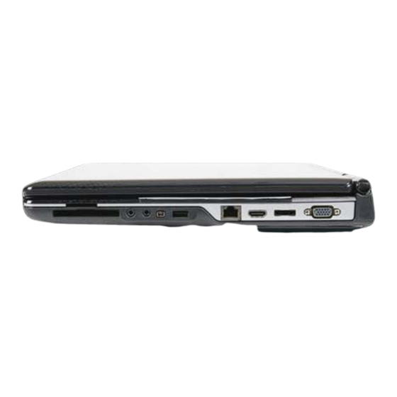
Left View Figure 1-3. Left View Table 1-3. Left View Icon Item Description DC-in jack Connects to the AC adapter. Ethernet (RJ-45) port Connects to an 10/100/1000-based Ethernet network. External display Connects to a display device (e.g., external (VGA) port monitor, LCD projector). -
Page 24: Right View
Right View Figure 1-4. Right View Table 1-4. Right View Icon Item Description USB 2.0 port Connects to USB devices (e.g., USB mouse, USB camera). Optical disc drive Internal optical disc drive; accepts CDs or DVDs. (ODD) ODD access indicator Lights up when the optical drive is active. -
Page 25: Base View
Base View Figure 1-5. Base View Table 1-5. Base View Icon Item Description Battery pack Provides power to the computer when the power cord is unplugged. Battery release latch Releases the battery for removal. HDD/memory/WLAN Houses the computer's hard disk, memory, and module compartment WLAN (optional) modules. -
Page 26: Indicators
Indicators The computer has several easy-to-read status indicators. Figure 1-6. Indicators Table 1-6. Indicators Icon Item Description Power indicator Indicates the computer’s power status. Solid blue: The computer is turned on. Blinking amber: The computer is in power-saving mode. -
Page 27: Touchpad Basics
Touchpad Basics Figure 1-7. Touchpad The following items show you how to use the touchpad with Acer Bio-Protection fingerprint reader. Move finger across the touchpad (1) to move the cursor. Press the left (3) and right (2) buttons located beneath the touchpad to perform ... -
Page 28: Keyboard
Keyboard ® The keyboard contains an numeric keypad, inverted “T” cursor key, Windows key, Application key, function lock keys, hotkeys, and media control keys controlling various computer features. Figure 1-8. Keyboard 1-18 Hardware Specifications and Configurations... -
Page 29: Lock Keys
Lock Keys The keyboard has three lock keys which the user can toggle on and off. Figure 1-9. Keyboard Lock Keys Table 1-8. Keyboard Lock Keys Lock key Description Caps Lock When On, all typed alphabetic characters appears in uppercase. Num Lock Off by default. -
Page 30: Windows Keys
Windows Keys The keyboard has two keys that perform Windows-specific functions. Figure 1-10. Windows-specific Keys Table 1-9. Windows-specific Keys Description Windows Pressed alone, this key has the same effect as clicking on the Windows Logo key Start button; it launches the Start menu. It can also be used with other keys to provide a variety of functions. -
Page 31: Hotkeys
Hotkeys The computer uses hotkeys or key combinations to access most computer controls. To activate hotkeys, press and hold the Fn key before pressing the key in the combination. Figure 1-11. Hotkeys Table 1-10. Hotkeys Hotkey Icon Function Description Communication Toggles the WiFi, 3G and/or Bluetooth functions Fn+F3 device toggle... -
Page 32: Special Keys
Special Keys The Euro symbol 1. Open a text editor or word processor. 2. Hold Alt Gr and then press the € key. NOTE: NOTE: Some fonts and software do not support the Euro symbol. See www.microsoft.com/typography/faq/faq12.htm for more information. The US dollar sign 1. - Page 33 D2D Recovery The Acer Disk to Disk (D2D) recovery function allows you to use the recovery partition to troubleshoot your computer. 1. Restart the computer. 2. During POST, press F1 to access the BIOS Setup screen. 3. Press to select the Main menu.
- Page 34 System Block Diagram Figure 1-12. System Block Diagram 1-24 Hardware Specifications and Configurations...
-
Page 35: Specification Tables
Specification Tables Computer Specifications Item Metric Imperial Dimensions Width 38.16 cm 15.02 in Depth 25.3 cm 9.96 in Height 2.52–3.32 cm 0.99–1.3 in Weight (equipped with 6-cell UMA: 2.53 kg UMA: 5.58 lb battery pack, HDD, and ODD) Discrete: 2.60 kg Discrete: 5.74 lb ... - Page 36 System Board Item Specification Core logic AMD A60M Fusion™ Controller Hub Graphics UMA: AMD A60M Fusion™ Controller Hub Discrete: AMD Radeon™ HD 6620G Graphics, AMD Radeon™ HD 6520G Graphics, AMD Radeon™ HD 6480G Graphics, AMD Radeon™ HD 6380G Graphics with 512 MB of dedicated system memory, supporting Unified Video Decoder 3 (UVD3), OpenCL®...
- Page 37 Processor Specifications Item Cores/ Max Turbo Core Voltage Speed Threads Freq Tech Cache A8-3500M 1.50 GHz 4C/- 2.40 GHz 4 MB 35 W 1.1 V A6-3400M 1.40 GHz 4C/- 2.30 GHz 4 MB 35 W 1.1 V A4-3300M 1.90 GHz 2C/- 2.50 GHz 2 MB...
- Page 38 Memory Combinations Slot 1 (MB) Slot 2 (MB) Total Memory (MB) 1024 1024 2048 2048 1024 1024 2048 1024 2048 3072 2048 2048 4096 1024 4096 5120 2048 4096 6144 4096 4096 8192 NOTE: The preceding table lists possible system memory configurations. The configuration of slot 1 and slot 2 could be reversed.
- Page 39 Microsoft SLP 1.0 support Microsoft OA 2.0 and 2.1 support Keyboard Item Specification Type Acer FineTouch™ keyboard Total number of keys 105-/106-/109-keys Windows logo key Internal and external USB keyboard work simultaneously? Features Overlay numeric keys ...
- Page 40 Hard Disk Drive Item Specification Vendor and models Hitachi Hitachi Seagate Toshiba Toshiba HTS54502 ST950032 MK7559G HTS54323 MK6459G 5B9A300 5AS, SXP, 2A7A384, SXP, Western Western Western Western Digital Digital Digital Digital WD7500B WD5000B WD3200B WD6400B PVT-22HX PVT-22HX PVT-22ZE PVT-22HX Product series Hitachi Travelstar Z5K320/7K500/5K500.B ...
- Page 41 Super-Multi Drive Item Specification Vendor and models HLDS GT32N/GT34N PLDS DS-8A5SH Interface Slim-type SATA Transfer rates 4X Blu-ray Disc/DVD-Super 8X DVD-Super Multi Multi double-layer drive: double-layer drive Read Write Read Write CD-ROM CD-R CD-RW DVD-ROM DVD-R DVD+R DVD-ROM DL DVD-R DL DVD+R DL DVD-RW...
-
Page 42: Card Reader
Card Reader Item Specification Controller Broadcom BCM57785X Cards supported MultiMediaCard™ (MMC) MultiMediaCard Plus (MMCplus™) Secure Digital™ (SD) xD-Picture Card™ (xD) Memory Stick™ (MS) Memory Stick PRO™ (MS PRO) cards Manufacturing technology 65 nm LCD Panel Item Specification Vendor and models... -
Page 43: Supported Lcd Resolutions
Supported LCD Resolutions Resolution Discrete 800x600, 60 Hz 16:9 1024x768, 60 Hz 16:9 1280x600, 60 Hz 16:9 1280x720, 60 Hz 16:9 1280x768, 60 Hz 16:9 1360x768, 60 Hz 16:9 1366x768, 60 Hz, 16:9 Supported GPU Resolutions Resolution Discrete 800x600, 60 Hz 16:9 1024x768, 60 Hz 16:9 1280x600, 60 Hz 16:9 1280x720, 60 Hz 16:9... -
Page 44: Audio Codec
Audio Codec Item Specification Controller Realtek ALC271X_VB3 Features Meets Microsoft WLP 3.10 and future WLP audio requirements WaveRT-based audio function driver for Windows Vista Ć EAX. 1.0 & 2.0 compatible Direct Sound 3D. compatible A3D compatible I3DL2 compatible ... -
Page 45: Webcam
Item Specification Internal speaker/quantity Yes, two speakers Webcam Item Specification Vendor and models Chicony CNFA1A621004970LH Lite-On 10P2SF205/10P2SF137 Suyin HF1316-P80A-SS06/HF2015-A821-OV01 Resolution 1.3 MP HD Item Specification LAN controller Broadcom BCM57785X LAN connector type RJ-45 LAN connector location Right side Features Integrated 10/100/1000BASE-T transceiver with: 10/100/1000BASE-T triple-speed MAC... -
Page 46: Bluetooth
Bluetooth Item Specification Module Foxconn ATH BU12 V2.1 6PIN Foxconn ATH BU12 V3.0 6PIN Version Bluetooth 3.0 + HS, Bluetooth 2.1 + EDR Interface USB 2.0 Data transfer rate 2.1 Mbit/s Radio frequency 2.4 GHz CMOS technology 0.13µ USB Interface Item Specification... -
Page 47: System Led Indicators
System LED Indicators Item Specification Power status Solid blue: The computer is turned on. Blinking amber: The computer is in power-saving mode. Indicator off: The computer is turned off. Battery status AC adapter connected: Solid blue: The battery charge is at full capacity. ... -
Page 48: System Power Management
System Power Management Item Specification Power management system ACPI 3.0-compliant Power global states G3 Mechanical Off - This off state is entered through a mechanical means; no electrical current is running through the circuitry and it can be worked on without damaging the hardware or endangering service personnel. - Page 49 System Interrupt Specification Hardware IRQ System Function IRQ0 System timer IRQ1 Standard PS/2 keyboard IRQ2 Not in use IRQ3 Not in use IRQ5 Not in use IRQ6 Not in use IRQ7 Not in use IRQ8 System CMOS/real time clock IRQ9 Broadcom xD Picture Card Host Controller IRQ10 Not in use...
- Page 50 I/O address (hex) System Function (shipping configuration) 0081-008F Direct memory access controller 0092-0092 Motherboard resources 00A0-00A1 Programmable Interrupt Controller 00B0-00B1 Motherboard resources 00B2-00B2 Motherboard resources 00B8-00B8 Motherboard resources 00BC-00BC Motherboard resources 00C0-00DE Direct memory access controller 00F0-00F0 Motherboard resources 00F0-00FE Numeric data processor 03B0-03BB AMD Radeon (TM) HD 6380G...
- Page 51 I/O address (hex) System Function (shipping configuration) 2000-20FF AMD Radeon (TM) HD 6380G 2100-210F AMD SATA Controller 2110-2117 AMD SATA Controller 2118-211F AMD SATA Controller 2120-2123 AMD SATA Controller 2124-2127 AMD SATA Controller 8100-81FF Motherboard resources 8200-82FF Motherboard resources 1-41 Hardware Specifications and Configurations...
- Page 52 1-42 Hardware Specifications and Configurations...
- Page 53 CHAPTER System Utilities...
- Page 54 BIOS Setup Utility........2-3 Navigating the BIOS Utility .
-
Page 55: Bios Setup Utility
System Utilities BIOS Setup Utility This utility is a hardware configuration program built into a computer’s BIOS (Basic Input/Output System). The utility is pre-configured and optimized so most users do not need to run it. If configuration problems occur, the setup utility may need to be run. Refer to Chapter 4, Troubleshooting when a problem arises. -
Page 56: Bios Menus
BIOS Menus This section describes the Phoenix SecureCore Tiano BIOS Setup Utility menu tabs. NOTE: NOTE: The screenshots used in this chapter are for reference only. Actual values can vary depending on the computer model. Information This tab shows a summary of the computer‘s hardware information. P h o e n i x S e c u r e C o r e Ti a n o S e t u p I n f o r m a t i o n M a i n... -
Page 57: Product Name
Table 2-1. Hardware Information (Continued) Parameter Description Asset Tag Number Asset tag number of the computer Product Name Model name of the computer Manufacturer Name Computer manufacturer UUID The universally unique identifier tag assigned to the computer Main Use this tab to set the system time and date, enable or disable boot options, and enable or disable the D2D recovery feature. - Page 58 Table 2-2. BIOS Main (Continued) Parameter Description Format/Option Quiet Boot Show the original equipment manufacturer Option: Enabled or (OEM) screen during system boot instead of Disabled the typical POST screen Graphic Mode Option to set the graphic device. Option: Switchable, Integrated or Discrete Network Boot Option to boot system from LAN...
-
Page 59: Setting A Password
Table 2-3. BIOS Security (Continued) Parameter Description Option HDD Password State Hard drive password setting or Set Clear Set Supervisor Password Option to set the supervisor password – Set User Password Option to set a user password – Set HDD Password Option to set the hard drive password –... -
Page 60: Removing A Password
Removing a Password Perform the following: 1. Press to highlight a Set _______ Password parameter and press Enter. The Set _______ Password dialog box appears. Set Supervisor Password Enter Current Password [ Enter New Password [ Confirm New Password [ Figure 2-5. -
Page 61: Hard Disk Drive
5. Press Enter. Computer sets Supervisor Password parameter to Set. NOTE: NOTE: Users can choose to enable the Password on Boot parameter. 6. Press F10 to save changes and exit from the BIOS Setup Utility. Boot Use this tab to set the preferred drive sequence in which the Setup Utility attempts to boot the operating system. -
Page 62: Exit Saving Changes
Exit Use the Exit tab to save or discard changes and close the BIOS Setup Utility. P h o e n i x S e c u r e C o r e Ti a n o S e t u p I n f o r m a t i o n M a i n S e c u r i t y... -
Page 63: Bios Flash Utilities
BIOS Flash Utilities BIOS Flash memory updates are required for the following conditions: New versions of system programs New features or options Restore a BIOS when it becomes corrupted. Use the Flash utility to update the system BIOS Flash ROM. NOTE: NOTE: If a Crisis Recovery Disc is not available, create one before Flash utility is used. -
Page 64: Winflash Utility
DOS Flash Utility Perform the following to use the DOS Flash Utility: 1. Press F2 during boot to enter Setup Menu. 2. Select Boot Menu to modify boot priority order. Example: If using USB HDD to Update BIOS, move USB HDD to position 1. P h o e n i x S e c u r e C o r e Ti a n o S e t u p I n f o r m a t i o n M a i n... -
Page 65: Remove Hdd/Bios Password Utilities
Remove HDD/BIOS Password Utilities This section explains how to remove the HDD and BIOS passwords. Removing the HDD Password NOTE: NOTE: If the incorrect HDD password is entered three times in succession, an error is generated. (Figure 2-11) Password Error Status HDD password error code Figure 2-11. -
Page 66: Removing The Bios Passwords
4. Select option 2 (upper case ASCII code) and press Enter. 5. Write down the generated master password. 6. Reboot the computer. 7. In the HDD password prompt, type the master password generated in step 5, then press Enter. Removing the BIOS Passwords To clear a lost BIOS password (user or supervisor password), you need to short the clear password hardware gap (G1901) located on the mainboard. -
Page 67: Clearing The Bios Passwords
Clearing the BIOS Passwords 1. Shut down the computer and disconnect the AC adapter and all other peripherals from the computer. 2. Removing the battery pack and lower case cover. 3. If the Mini Card slot is occupied, remove the installed wireless module. 4. -
Page 68: Using Dmi Tools
Using DMI Tools The DMI (Desktop Management Interface) Tool copies BIOS information to EEPROM (Electrically Erasable Programmable Read-Only Memory). Used in the DMI pool for hardware management. LAN EEPROM Utility LAN EEPROM Utility enables to change the MAC address. Perform the following steps to use the LAN EEPROM Utility: 1. - Page 69 CHAPTER Machine Maintenance...
- Page 70 Machine Disassembly and Replacement....3-5 Recommended Equipment ......3-5 Replacement Requirements.
- Page 71 LCD Module Reassembly Process......3-55 Replacing the Antennas......3-55 Replacing the Camera Board .
-
Page 73: Machine Disassembly And Replacement
Machine Maintenance Machine Disassembly and Replacement This chapter contains step-by-step procedures on how to disassemble the notebook computer for maintenance and troubleshooting. Cable paths and positioning may not represent the actual model. During the removal and installation of the components, ensure all available cable channels and clips are used and that the cables are replaced in the same position. -
Page 74: Pre-Disassembly Instructions
Pre-disassembly Instructions Before proceeding with the disassembly procedure, make sure that you do the following: 1. Turn off the power to the system and all peripherals. 2. Unplug the AC adapter and all power and signal cables from the system. Figure 3-1. -
Page 75: Disassembly Process
For example, if you want to remove the mainboard, you must first remove the keyboard, then disassemble the inside assembly frame in that order. Table 3-1. Main Screw List Screw Quantity Acer Part Number M2.5 × L6 86.00E12.536 M2 × L3 86.00F80.723 M2.5 ×... -
Page 76: External Module Disassembly Process
WLAN MODULE MODULES MODULE Figure 3-2. External Modules Disassembly Flowchart Table 3-2. Screw List Step Screw Quantity Acer Part Number ODD Module Disassembly M2.5 × L6 86.00E12.536 ODD Bracket Disassembly M2 × L3 86.00F80.723 Base Door Disassembly M2.5 × L6 86.00E12.536... -
Page 77: Removing The Battery Pack
Removing the Battery Pack 1. Turn the computer over so that the base is facing up. 2. Slide and hold the battery release latch all the way through to release the battery pack. Figure 3-3. Battery Pack 3. Remove the battery pack from its bay. Figure 3-4. -
Page 78: Remove The Dummy Card
Remove the Dummy Card 1. Push against the dummy card, as if you were pushing it further into the slot (a). 2. Pull the dummy card out (b). Figure 3-5. Dummy Card Machine Maintenance... -
Page 79: Removing The Odd Module
Removing the ODD Module 1. Remove the screw securing the ODD module. Figure 3-6. ODD Module Screw Table 3-3. Screw Step Screw Quantity Screw Type ODD Module Disassembly M2.5 × L6 2. Slide the drive out of the drive bay. Figure 3-7. - Page 80 3. Remove the screws securing the ODD bracket. Figure 3-8. ODD Bracket Screws Table 3-4. Screws Step Screw Quantity Screw Type ODD Bracket Disassembly M2 × L3 4. Detach the bracket from the module. Figure 3-9. ODD Bracket Machine Maintenance...
- Page 81 5. Pry the ODD bezel off the module. Figure 3-10. ODD Bezel Machine Maintenance...
-
Page 82: Removing The Base Door
Removing the Base Door 1. Perform the “Removing the Battery Pack” procedure described on page 3-9. 2. Remove the screws securing the base door. Figure 3-11. Base Door Screws Table 3-5. Screws Step Screw Quantity Screw Type Base Door Disassembly M2.5 ×... -
Page 83: Removing The Hdd Module
Removing the HDD Module 1. Perform the “Removing the Base Door” procedure described on the preceding section. 2. Remove the HDD screw. Figure 3-13. HDD Module Screw Table 3-6. Screw Step Screw Quantity Screw Type HDD Module Disassembly M2.5 × L4 3. - Page 84 4. Remove the two screws securing the HDD bracket (a) and then remove the HDD (b). Figure 3-15. HDD Bracket Screw and HDD Bracket Table 3-7. Screws Step Screw Quantity Screw Type HDD Bracket Disassembly M3 × L4 Machine Maintenance...
-
Page 85: Removing The Wlan Module
Removing the WLAN Module 1. Perform the “Removing the Base Door” procedure described on page 3-14. 2. Unplug the two antenna cables from the WLAN module. IMPORTANT: For reference during machine reassembly, note which cable color corresponds to the main (black) and auxiliary (white) connectors. Figure 3-16. - Page 86 4. Remove the WLAN module from the slot. Figure 3-18. WLAN Module Machine Maintenance...
-
Page 87: Removing The Memory Modules
Removing the Memory Modules 1. Perform the “Removing the Base Door” procedure described on page 3-14. 2. Push out the latches on both sides of the memory slot until the module tilts upward (a), and then remove the DM1 slot module (b). Figure 3-19. -
Page 88: Removing The Lan Link Cable
Removing the LAN Link Cable 1. Perform the “Removing the Base Door” procedure described on page 3-14. 2. Disconnect one end of the LAN link cable from the mainboard. Figure 3-21. LAN Link Cable 3. Disconnect the other end from the LAN cable. Figure 3-22. -
Page 89: Main Unit Disassembly Process
BOARD THERMAL BATTERY MODULE Figure 3-23. Main Unit Disassembly Flowchart Table 3-9. Screw List Step Screw Quantity Acer Part Number Palmrest Module/Upper Cover Disassembly M2.5 × L6 86.00E12.536 M2 × L3 86.00F80.723 Power Button Board Disassembly M2 x L3 86.00F80.723... -
Page 90: Removing The Keyboard
Removing the Keyboard IMPORTANT: The keyboard is easily warped or damaged during the removal process. Take care not to use excessive force when removing. 1. Use a non-marring plastic flat-blade screwdriver to push the latches on the top side of the keyboard. -
Page 91: Removing The Palmrest Module/Upper Cover
Removing the Palmrest Module/Upper Cover 1. Perform the “Removing the ODD Module” and “Removing the HDD Module” procedures described on pages 3-11and 3-15 respectively. 2. Perform the “Removing the Keyboard” procedure described on the preceding section. 3. Open the power button board cable connector latch (a) and then disconnect the cable (b). Figure 3-26. - Page 92 5. Disconnect the speaker cable. Figure 3-28. Speaker Cable 6. Remove the top side screws securing the upper cover. Figure 3-29. Upper Cover Screw – Top Side Table 3-10. Screws Step Screw Quantity Screw Type Upper Cover Disassembly M2.5 × L6 Machine Maintenance...
- Page 93 7. Remove the base side screws securing the upper cover. Figure 3-30. Upper Cover Screws – Base Side Table 3-11. Screws Step Screw Quantity Screw Type Upper Cover Disassembly M2.5 × L6 11 (#1-11) M2 × L3 3 (#12-14) 8. Locate the small gaps between the upper cover and lower case, and insert a small flat-blade screwdriver or non-marring scribe into each gap to separate the one from the other.
-
Page 94: Removing The Power Button Board
Removing the Power Button Board 1. Perform the “Removing the Palmrest Module/Upper Cover” procedure described on the preceding section. 2. Carefully pull the black mylar tabs from the power button board. Figure 3-32. Power Button Board Tapes 3. Open the connector latch (a) and then remove the cable (b). Figure 3-33. - Page 95 4. Remove the screws securing the power button board. Figure 3-34. Power Button Board Screws Table 3-12. Screws Step Screw Quantity Screw Type Power Button Board Disassembly M2 × L3 5. Remove the power button board from the upper cover. Figure 3-35.
-
Page 96: Removing The Speakers
Removing the Speakers 1. Perform the “Removing the Palmrest Module/Upper Cover” procedure described on page 3-23. 2. Carefully pull the black mylar tape from the speaker cables and then release the cables from the cable guides. Figure 3-36. Speaker Tapes 3. - Page 97 4. Lift the speakers from the upper cover. Figure 3-38. Speaker Screws Machine Maintenance...
-
Page 98: Removing The Touchpad Board
Removing the Touchpad Board 1. Perform the “Removing the Palmrest Module/Upper Cover” procedure described on page 3-23. 2. Open the connector latch (a) and then disconnect the cable (b). Figure 3-39. Touchpad Board Cable 3. Detach the silver tape securing the touchpad board. Figure 3-40. - Page 99 4. Insert a small flat-blade screwdriver between the touchpad board and the upper cover, and carefully pry the board loose. Remove the touchpad board from the palm rest. Figure 3-41. Touchpad Board NOTE: NOTE: A circuit board that is > 10cm has been highlighted with a yellow rectangle in Figure 3-41.
-
Page 100: Removing The Usb Board
Removing the USB Board 1. Perform the “Removing the Palmrest Module/Upper Cover” procedure described on page 3-23. 2. Open the connector latches on both ends of the USB board cable (a) and then disconnect the USB board cable from both the mainboard and the USB board (b). Remove the USB board cable from the lower case (c). - Page 101 4. Release the USB board from its securing tab and then remove the USB board from the lower case. Figure 3-44. USB Board Machine Maintenance...
-
Page 102: Removing The Bluetooth Module
Removing the Bluetooth Module 1. Perform the “Removing the Palmrest Module/Upper Cover” procedure described on page 3-23. 2. Disconnect the Bluetooth cable. Figure 3-45. Bluetooth Cable 3. Detach the Bluetooth module from the mainboard. Figure 3-46. Bluetooth Module Machine Maintenance... -
Page 103: Removing The Rtc Battery
Removing the RTC Battery 1. Perform the “Removing the Palmrest Module/Upper Cover” procedure described on page 3-23. 2. Insert a small flat-blade screwdriver between the battery and spring latch to dislodge the battery (a) and then remove the battery (b). Figure 3-47. -
Page 104: Removing The Mainboard
Removing the Mainboard 1. Perform the “Removing the ODD Module” and “Removing the HDD Module” procedures described on pages 3-11 3-15 respectively. 2. If a WLAN module is installed, remove it. Perform the “Removing the WLAN Module” procedure described on pages 3-17. 3. - Page 105 6. Carefully pull the mainboard out of the base enclosure. Figure 3-50. Mainboard NOTE: NOTE: A circuit board that is >10 cm2 has been highlighted with a yellow rectangle in Figure 3-50. Follow the local regulations for disposing this type of circuit board. 7.
-
Page 106: Removing The Thermal Module
Removing the Thermal Module 1. Perform the “Removing the Mainboard” procedure described on the preceding section. 2. Disconnect the thermal module fan cable. Figure 3-52. Fan Cable 3. Loosen the spring-loaded captive screws securing the thermal module. Follow the screw sequence indicated on Figure 3-53. - Page 107 4. Remove the thermal module from the mainboard. Figure 3-54. Thermal Module Machine Maintenance...
-
Page 108: Removing The Cpu
Removing the CPU 1. Perform the “Removing the Mainboard” procedure described on page 3-36. 2. Use a flat-blade screwdriver to turn the CPU socket lock screw counter-clockwise. Figure 3-55. CPU Socket Screw 3. Remove the CPU from the mainboard. Figure 3-56. CPU Machine Maintenance... -
Page 109: Removing The Lan Cable
Removing the LAN Cable 1. Perform the “Removing the Mainboard” procedure described on page 3-36. 2. Remove the LAN cable from the lower case. Figure 3-57. LAN Cable Machine Maintenance... -
Page 110: Removing The Lcd Module
Removing the LCD Module 1. Perform the “Removing the Mainboard” procedure described on page 3-36. 2. Release the antenna cable from its top side latches. Figure 3-58. Antenna Cable – Top Side Latches 3. Release the LCD cable from its top side latches. Figure 3-59. - Page 111 4. Remove the DC input cable from the lower case. Figure 3-60. DC Input Cable – Top Side Latches 5. Remove the screws securing the LCD module. Figure 3-61. LCD Module Hinge Screws Table 3-17. Screws Step Screw Quantity Screw Type LCD Module Disassembly M2.5 ×...
- Page 112 6. Remove the LCD module from the lower case. Figure 3-62. LCD Module Machine Maintenance...
-
Page 113: Lcd Module Disassembly Process
CAMERA BRACKET BRACKET CABLE Figure 3-63. LCD Module Disassembly Flowchart Table 3-18. Screw List Step Screw Quantity Acer Part Number LCD Bezel Disassembly M2.5 × L4 86.00H36.534 LCD Panel Disassembly M2.5 × L4 86.00H36.534 LCD Brackets Disassembly M2 × L3 86.00F80.723... -
Page 114: Removing The Lcd Bezel
Removing the LCD Bezel 1. Perform the “Removing the LCD Module” procedure described on page 3-42. 2. Remove the screw rubber covers on the lower corners of the LCD bezel. Figure 3-64. LCD Bezel Screw Covers 3. Remove the screws on the lower corners of the LCD bezel. Figure 3-65. - Page 115 4. Carefully pry loose the LCD bezel from the LCD cover. Start on the bottom side, continue to the left and right sides, and finally the top side (a) and then remove the bezel from the LCD module (b). Figure 3-66. LCD Bezel Machine Maintenance...
-
Page 116: Removing The Lcd Panel
Removing the LCD Panel 1. Perform the “Removing the LCD Bezel” procedure described on the preceding section. 2. Disconnect the camera board cable. Figure 3-67. Camera Board Cable 3. Detach the black tape covering the microphone and LCD-webcam cables. Figure 3-68. Microphone and LCD-webcam Cables’ Tape 4. - Page 117 5. Release the LCD-webcam cable from its LCD cover latches. Figure 3-70. LCD-webcam Cable 6. Remove the screws securing the LCD panel. Figure 3-71. LCD Panel Screws Table 3-20. Screws Step Screw Quantity Screw Type LCD Panel Disassembly M2.5 × L4 Machine Maintenance...
- Page 118 7. Lift the panel from the LCD cover. Figure 3-72. LCD Panel 8. Turn the LCD on its front to access the LCD cable. 9. Detach the webcam side of the LCD-webcam cable from the LCD panel (a). Detach the transparent tape securing the LCD cable (b) and then disconnect the cable from the LCD board (c).
-
Page 119: Removing The Lcd Brackets
Removing the LCD Brackets 1. Perform the “Removing the LCD Panel” procedure described on the preceding section. 2. Remove the screws securing the left and right LCD brackets and then remove the left and right brackets. Figure 3-74. LCD Bracket Screws Table 3-21. -
Page 120: Removing The Camera Board
Removing the Camera Board 1. Perform the “Removing the LCD Panel” procedure described on page 3-48. 2. Carefully pry the camera board off the LCD cover. Figure 3-75. Camera Board Machine Maintenance... -
Page 121: Removing The Microphone
Removing the Microphone 1. Perform the “Removing the LCD Panel” procedure described on page 3-48. 2. Release the microphone cable from the adhesive tabs securing them. Figure 3-76. Microphone Cable Tapes 3. Remove the microphone from the LCD cover. Figure 3-77. Microphone Machine Maintenance... -
Page 122: Removing The Antennas
Removing the Antennas 1. Perform the “Removing the LCD Panel” procedure described on page 3-48. 2. Release the antenna cables from the cable guides and detach the tin foil tapes, then remove the antenna cables from the LCD cover. Figure 3-78. Antennas Machine Maintenance... -
Page 123: Lcd Module Reassembly Process
LCD Module Reassembly Process Replacing the Antennas 1. Place the antenna cables on the LCD cover, secure the cables with tin foil tapes and then route the cables to the cable guides. Figure 3-79. Antennas Machine Maintenance... -
Page 124: Replacing The Camera Board
Replacing the Camera Board 1. Place the camera board on the LCD cover and press down to secure in place. Figure 3-80. Camera Board Machine Maintenance... -
Page 125: Replacing The Microphone
Replacing the Microphone 1. Place the microphone on the LCD cover. Figure 3-81. Microphone 2. Route the microphone cable to the cable guides and then secure the cable underneath the adhesive tabs. Figure 3-82. Microphone Cable Tapes Machine Maintenance... -
Page 126: Replacing The Lcd Brackets
Replacing the LCD Brackets 1. Attach the LCD left and right brackets to the LCD panel (a) and then secure the brackets with the four screws (b). Figure 3-83. LCD Brackets Table 3-22. Screws Step Screw Quantity Screw Type LCD Brackets Assembly M2 ×... -
Page 127: Replacing The Lcd Panel
Replacing the LCD Panel 1. Connect the LCD cable to the LCD board (a) and secure LCD cable connection with the transparent tape (b). Secure the webcam side of the LCD-webcam cable in place using double-sided adhesive tape (c). Figure 3-84. LCD-webcam Cable 2. - Page 128 3. Connect the microphone cable. Figure 3-86. Microphone Cable 4. Secure the cables underneath the black tape. Figure 3-87. Microphone and LCD-webcam Cable 5. Secure the LCD-webcam cable to the cable guides. Figure 3-88. LCD-webcam Cable Machine Maintenance...
- Page 129 6. Secure the LCD panel with the four screws. Figure 3-89. LCD Panel Screws Table 3-23. Screws Step Screw Quantity Screw Type LCD Panel Assembly M2.5 × L4 7. Connect the camera board cable. Figure 3-90. Camera Board Cable Machine Maintenance...
-
Page 130: Replacing The Lcd Bezel
Replacing the LCD Bezel 1. Place the bezel on top the LCD panel and then press the bezel on all sides until it snaps into place. NOTE: NOTE: Make sure that the LCD, camera board, microphone and antenna cables are properly routed on the hinge sides and there is no gap between the bezel and the LCD cover. - Page 131 3. Secure the bezel with the two screw covers. Figure 3-93. LCD Bezel Screw Covers Machine Maintenance...
-
Page 132: Main Unit Reassembly Process
Main Unit Reassembly Process Replacing the LCD Module 1. Position the LCD module on the lower case. Figure 3-94. LCD Module 2. Secure LCD module with the two screws. Figure 3-95. LCD Module Hinge Screws Table 3-25. Screws Step Screw Quantity Screw Type LCD Module Assembly... - Page 133 3. Route the antenna cables through their top side latches and then insert the antenna cables into the openings on the lower case. Figure 3-96. Antenna Cables – Top Side Latches 4. Route the LCD cable through their top side latches. Figure 3-97.
- Page 134 5. Position the DC input cable on the lower case. Figure 3-98. DC Input Cable Machine Maintenance...
-
Page 135: Replacing The Lan Cable
Replacing the LAN Cable 1. Position the LAN cable on the lower case and then press down on the cable to secure it on the lower case. Make sure to secure the cable in place using double-sided adhesive tape. Figure 3-99. LAN Cable Machine Maintenance... -
Page 136: Replacing The Cpu
Replacing the CPU 1. Place the CPU in the socket. Figure 3-100. CPU 2. Make sure the gold arrow on the corner of the CPU is aligned with the beveled corner of the socket. The CPU will easily fit into the socket if you orient it properly. Figure 3-101. -
Page 137: Replacing The Thermal Module
Replacing the Thermal Module IMPORTANT: Make sure all thermal pads for the mainboard chipsets and VRAMs are in place before replacing the thermal module. 1. Use a lint-free cloth or cotton swab soaked in isopropyl alcohol or acetone to remove all traces of thermal grease from the contact surfaces on both the thermal module and the CPU. - Page 138 4. Tighten the spring-loaded captive screws to secure the thermal module. Follow the screw sequence indicated on Figure 3-104. Figure 3-104. Thermal Module Screws Table 3-26. Screws Step Screw Quantity Screw Type Thermal Module Assembly – – 5. Connect the fan cable to the mainboard. Figure 3-105.
-
Page 139: Replacing The Rtc Battery
Replacing the RTC Battery 1. Place the RTC battery into the empty socket on the mainboard with the “+” symbol facing up (a) and then press down to secure it to the mainboard (b). Figure 3-106. RTC Battery Machine Maintenance... -
Page 140: Replacing The Mainboard
Replacing the Mainboard 1. Connect the DC input cable (a) and turn the mainboard over (b). Figure 3-107. RF Switch and DC input Cables 2. Slide the mainboard toward the left side of the lower case, with the I/O ports of the mainboard extruding from their port holes, then lower the mainboard in place. - Page 141 3. Secure the mainboard with the one screw. Figure 3-109. Mainboard Screw Table 3-27. Screw Step Screw Quantity Screw Type Mainboard Assembly M2 × L3 4. Connect the LCD cable to the mainboard. Figure 3-110. LCD Cable Machine Maintenance...
-
Page 142: Replacing The Bluetooth Module
Replacing the Bluetooth Module 1. Place the Bluetooth module on the mainboard and press down to secure in place. Figure 3-111. Bluetooth Module 2. Connect the Bluetooth cable. Figure 3-112. Bluetooth Module Machine Maintenance... -
Page 143: Replacing The Usb Board
Replacing the USB Board 1. Slide the USB board toward the right side of the lower case, with the I/O ports of the USB board extruding from their port holes, and then lower the USB board under the securing tab. Figure 3-113. - Page 144 3. Position the USB board cable on the lower case (a). Connect the USB board cable to both the mainboard and the USB board (b) and then close the connector latches (c). Figure 3-115. USB Board Cable Machine Maintenance...
-
Page 145: Replacing The Touchpad Board
Replacing the Touchpad Board 1. Attach a double-sided adhesive tape on the back side of the touchpad board. Position the board on the upper cover and press down to secure the board in place. Figure 3-116. Touchpad Board 2. Secure a tin foil tape over the touchpad board. Figure 3-117. - Page 146 3. Connect the touchpad board cable (a) and then close the connector latch (b). Figure 3-118. Touchpad Board Cable Machine Maintenance...
-
Page 147: Replacing The Speakers
Replacing the Speakers 1. Position the speakers on the upper cover. Figure 3-119. Speakers 2. Secure the speakers with the four screws. Figure 3-120. Speaker Screws Table 3-29. Screws Step Screw Quantity Screw Type Speakers Assembly Special screw Machine Maintenance... - Page 148 3. Route the speaker cables on the cable guide and then secure the cables underneath the black mylar tape. Figure 3-121. Speaker Tape Machine Maintenance...
-
Page 149: Replacing The Power Button Board
Replacing the Power Button Board 1. Position the power button board on the upper cover aligning the tabs in the cover (a) and then lower the board in place (b). Figure 3-122. Power Button Board 2. Secure the power button board with the two screws. Figure 3-123. - Page 150 3. Connect the power button board cable (a) and then close the connector latch (b). Press down on the cable to secure it in place. Figure 3-124. Power Button Board Cable 4. Press down on the black mylar tabs. Figure 3-125. Power Button Board Tape Machine Maintenance...
-
Page 151: Replacing The Palmrest Module/Upper Cover
Replacing the Palmrest Module/Upper Cover 1. Make sure the mainboard end of both the power button board and touchpad board cables are not caught underneath the upper cover. 2. Align the upper cover with the lower case, then press it down on all sides until it snaps into place. - Page 152 4. Connect the power button board cable (a) and then close the connector latch (b). Figure 3-128. Power Button Board Cable 5. Connect the touchpad board cable (a) and then close the connector latch (b). Figure 3-129. Touchpad Board Cable 6.
- Page 153 8. Secure the upper cover with the fourteen screws. Figure 3-131. Upper Cover Screws – Base Side Table 3-32. Screws Step Screw Quantity Screw Type Upper Cover Assembly M2.5 × L6 11 (#1-11) M2 × L3 3 (#12-14) Machine Maintenance...
-
Page 154: Replacing The Keyboard
Replacing the Keyboard 1. Connect the keyboard cable to the mainboard (a) and then close the connector latch (b). Align the tabs along the bottom edge of the keyboard with the corresponding slots on the upper cover, then press the keyboard down until the tabs snaps into place (c). Figure 3-132. -
Page 155: External Module Reassembly Process
External Module Reassembly Process Replacing the LAN Link Cable 1. Connect one end of the LAN link cable to the LAN cable. Figure 3-133. LAN Link Cable 2. Connect the other end of the LAN link cable to the mainboard and then position the cable on the mainboard. -
Page 156: Replacing The Memory Modules
Replacing the Memory Modules 1. Insert the memory module at a 30° angle into the DMI memory slot (a) and then press it down until it clicks into place (b). The module is keyed so it can only be inserted in one direction. If the module does not fit, make sure that the notch in the module lines up with the tab in the memory slot. -
Page 157: Replacing The Wlan Module
Replacing the WLAN Module 1. Insert the WLAN module at a 30° angle into the Mini Card slot. Figure 3-137. WLAN Module 2. Secure the WLAN module with a screw. Figure 3-138. WLAN Module Screw Table 3-33. Screw Step Screw Quantity Screw Type WLAN Module Assembly... - Page 158 3. Connect the main and auxiliary antenna cables to the WLAN module. IMPORTANT: The main antenna cable (black) should be attached to connector near the module screw; the auxiliary antenna cable (white) should be attached to the connector near the lower case cable opening. Figure 3-139.
-
Page 159: Replacing The Hdd Module
Replacing the HDD Module 1. Slide the HDD inside the bracket and then secure it with the two screws. Figure 3-140. HDD Bracket Screws Table 3-34. Screws Step Screw Quantity Screw Type HDD Bracket Assembly M3 × L4 2. Lay down the hard drive in the HDD bay and then slide it firmly into place. Figure 3-141. - Page 160 3. Secure the HDD to the bay with a screw. Figure 3-142. HDD Module Screw Table 3-35. Screw Step Screw Quantity Screw Type HDD Module Assembly M2.5 × L4 Machine Maintenance...
-
Page 161: Replacing The Base Door
Replacing the Base Door 1. Insert the tabs on the base door into the slots on the lower case (a) and then press down the base door into place (b). Figure 3-143. Base Door 2. Secure the base door with the three screws. Figure 3-144. -
Page 162: Replacing The Odd Module
Replacing the ODD Module 1. Attach the ODD bezel to the optical drive. Figure 3-145. ODD Bezel 2. Attach the bracket to the ODD. Figure 3-146. ODD Bracket Machine Maintenance... - Page 163 3. Secure the bracket with the two screws. Figure 3-147. ODD Bracket Screws Table 3-37. Screws Step Screw Quantity Screw Type ODD Bracket Assembly M2 × L3 4. Slide the optical drive into the drive bay. Figure 3-148. ODD Module Machine Maintenance...
- Page 164 5. Secure the ODD with a screw. Figure 3-149. ODD Bracket Screw Table 3-38. Screw Step Screw Quantity Screw Type ODD Module Assembly M2.5 × L6 Machine Maintenance...
-
Page 165: Replacing The Dummy Card
Replacing the Dummy Card 1. Insert the dummy card into the slot until it clicks into place. Figure 3-150. Dummy Card Machine Maintenance... -
Page 166: Replacing The Battery Pack
Replacing the Battery Pack 1. Turn the computer over so that the base is facing up. 2. Position the battery pack into the bay and then press it down until it snaps into place. Figure 3-151. Battery Pack Machine Maintenance... - Page 167 CHAPTER Troubleshooting...
- Page 168 Introduction ......... 4-3 General Information .
-
Page 169: Introduction
NOTE: NOTE: The diagnostic tests are intended for Acer products only. Non-Acer products, prototype cards, or modified options can give false errors and invalid system responses. 1. Obtain as much detailed information as possible about the problem. -
Page 170: Power On Issues
Power On Issues If the system does not power on, perform the following, one at a time, to correct the problem. Do not replace a non-defective FRU. Start Check AC/Battery Swap AC/Battery Power on Check Replace Daughter/B Daughter/B & FFC Rconnect PWR FFC whether OK Replace M/B... -
Page 171: No Display Issues
No Display Issues If the Display does not work, perform the following, one at a time. Do not replace a non-defective FRU: Start Power On Power on issues Is ext. DDR RAM Check module well connection connected? Replace Is ext. DDR RAM ext. -
Page 172: No Post Or Video
No POST or Video If the POST or video does not appear, perform the following one at a time. 1. Make sure that internal display is selected. Switch between the internal and external display by pressing Fn+F6. NOTE: NOTE: This hotkey may not apply to all models. Refer to the computer’s user manual for the applicable hotkey sequence. - Page 173 control/mouse wheel zoom feature in the application. If desktop display resolution is not normal, right-click on the desktop and select Personalize Display Settings. Click and drag the Resolution slider to the desired resolution. Click Apply and check the display. Readjust if necessary. ...
-
Page 174: Lcd Failure
LCD Failure If the LCD fails, perform the following, one at a time. Do not replace a non-defective FRU: Start Replace Check LCD LCD cable /LCD panel module? Reconnect Is LCD cable well connected? LCD cable Replace M/B Figure 4-3. LCD Failure Troubleshooting... -
Page 175: Keyboard Failure
Keyboard Failure If the Keyboard fails, perform the following, one at a time. Do not replace a non-defective FRU: Start Reconnect Is keyboard FPC well connected? Replace Is keyboard keyboard Replace M/B Figure 4-4. Keyboard Failure Troubleshooting... -
Page 176: Touchpad Failure
Touchpad Failure If the Touchpad fails, perform the following, one at a time. Do not replace a non-defective FRU: Start Check M/B Reconnect the T/P FFC T/P FFC to M/B Replace the Is T/P board T/P board or T/P FFC Replace M/B Figure 4-5. -
Page 177: Internal Speaker Failure
Internal Speaker Failure If internal Speakers fail, perform the following, one at a time. Do not replace a non-defective FRU: Start Reconnect the Is speaker cable well connected? speaker cable Is speaker Replace speaker Replace M/B Figure 4-6. Internal Speaker Failure Sound Problems Perform the following, one at a time. - Page 178 6. Navigate to Start Control Panel Hardware and Sound Sound. Confirm that Speakers are selected as the default audio device (green check mark). NOTE: NOTE: If Speakers do not show, right-click on the Playback tab and select Show Disabled Devices (clear by default).
-
Page 179: Microphone Failure
Microphone Failure If internal or external Microphones fail, perform the following, one at a time. Start Is MIC cable Reconnect the well connected? MIC cable Is MIC Replace the MIC Replace M/B Figure 4-7. Microphone Failure 1. Check that the microphone is enabled. Navigate to Start Control Panel Hardware and Sound ... -
Page 180: Usb Failure
USB Failure If the USB fails, perform the following, one at a time. Do not replace a non-defective FRU: Start Is USB board cable Reconnect the well connected? USB board cable Replace the Is USB board OK? USB cable or USB board Replace M/B Figure 4-8. -
Page 181: Wlan Failure
WLAN Failure If the WLAN fails, perform the following, one at a time. Do not replace a non-defective FRU: Start Is WLAN/Wimax Reconnect the antema well connected? WLAN/WiMax antenna Replace the Is antenna cable antenna cables Is WLAN/ Replace the WiMax card WLAN/WiMax card Check... -
Page 182: Bluetooth Failure
Bluetooth Failure If the Bluetooth fails, perform the following, one at a time. Do not replace a non-defective FRU: Start Reconnect the Is BT cable well connected? BT cable Replace the Is BT cable BT cable Replace the Is BT module BT module Replace the Check the... -
Page 183: Card Reader Failure
Card Reader Failure If the Card Reader fails, perform the following, one at a time. Do not replace a non-defective FRU: Start Check the I/O Check connection board assembly Check the IO/B Replace the I/O board Replace M/B Figure 4-11. Card Reader Failure 4-17 Troubleshooting... -
Page 184: Thermal Unit Failure
Thermal Unit Failure If the Thermal Unit fails, perform the following, one at a time. Do not replace a non-defective FRU: Start Is fan cable well connected? Reconnect cable Replace the Is fan module thermal module Is the thermal Reseat and fasten module well thermal module screws seated? -
Page 185: Other Functions Failure
Other Functions Failure 1. Check if drives are functioning correctly. 2. Check if external modules are functioning correctly. 3. Change mainboard to check if current one is defective. 4-19 Troubleshooting... -
Page 186: Intermittent Problems
1. Remove power from the computer. 2. Visually check the components for damage. If any problems are found, replace the FRU. 3. Remove or disconnect all of the following devices: Non-Acer devices Printer, mouse, and other external devices ... -
Page 187: Error Codes
Error Codes Table 4-2. Error Codes Error Codes Error Messages Equipment Configuration Error Causes: 1. CPU BIOS Update Code Mismatch 2. IDE Primary Channel Master Drive Error (The causes will be shown before “Equipment Configuration Error”) Memory Error at xxxx:xxxx:xxxxh (R:xxxxh, W:xxxxh) Real Time Clock Error CMOS Battery Bad CMOS Checksum Error... -
Page 188: Bios Beep Codes
BIOS Beep Codes Table 4-3. BIOS Beep Codes Code Beeps POST Routine Description Verify Real Mode Disable Non-Maskable Interrupt (NMI) Get CPU type Initialize system hardware Initialize chipset with initial POST values Set IN POST flag Initialize CPU registers Enable CPU cache Initialize caches to initial POST values Initialize I/O component Initialize the local bus IDE... - Page 189 Table 4-3. BIOS Beep Codes Code Beeps POST Routine Description Enable cache before system BIOS shadow 1-4-1-1 RAM failure on data bits xxxx of high byte of memory bus Test CPU bus-clock frequency Initialize Phoenix Dispatch Manager Warm start shut down Shadow system BIOS ROM Autosize cache Advanced configuration of chipset registers...
- Page 190 Table 4-3. BIOS Beep Codes Code Beeps POST Routine Description Setup System Management Mode (SMM) area Display external L2 cache size Load custom defaults (optional) Display shadow-area message Display possible high address for UMB recovery Display error messages Check for configuration errors Check for keyboard errors Set up hardware interrupt vectors Initialize coprocessor if present...
- Page 191 Table 4-3. BIOS Beep Codes Code Beeps POST Routine Description Check for SMART drive (optional) Shadow option ROMs Set up Power Management Initialize security engine (optional) Enable hardware interrupts Determine number of ATA and SCSI drives Set time of day Check key lock Initialize Typematic rate Erase F2 prompt...
- Page 192 Table 4-3. BIOS Beep Codes Code Beeps POST Routine Description Force check (optional) Extended checksum (optional) Unknown interrupt Initialize the chipset Initialize the bridge Initialize the CPU Initialize the system timer Initialize system I/O Check force recovery boot Checksum BIOS ROM Go to BIOS Set Huge Segment Initialize Multi Processor...
-
Page 193: Post Codes
POST Codes There are two types of POST codes: Progress Codes and Error Codes. Progress Codes are designed to show the execution point while booting or executing services. Error Codes are designed to halt on exceptional (fatal) error conditions. Component Codes The Component Code is an unsigned integer value that is assigned by the build process. - Page 194 Table 4-4. Component Codes Range Description POSTCODE_CC_HII_FORMS_BROWSER (0x3a) POSTCODE_CC_BOOT_MENU (0x3b) POSTCODE_CC_USER_MANAGER (0x3c) POSTCODE_CC_TIMER (0x3d) POSTCODE_CC_PCI_BUS (0x3e) POSTCODE_CC_ISA_BUS (0x3f) POSTCODE_CC_IDE_BUS (0x40) POSTCODE_CC_AHCI_BUS (0x41) POSTCODE_CC_SCSI_BUS (0x42) POSTCODE_CC_USB_BUS (0x43) POSTCODE_CC_FLOPPY (0x44) POSTCODE_CC_SERIAL_PORT (0x45) POSTCODE_CC_PS2_MOUSE (0x46) POSTCODE_CC_PS2_KEYBOARD (0x47) POSTCODE_CC_EHCI (0x48) POSTCODE_CC_XHCI (0x49) POSTCODE_CC_UHCI (0x4a) POSTCODE_CC_OHCI (0x4b) POSTCODE_CC_USB_KEYBOARD (0x4c) POSTCODE_CC_USB_MOUSE (0x4d)
- Page 195 Table 4-4. Component Codes Range Description 0xa0-0xaf These values are reserved for SecureCore Tiano™ platform components. POSTCODE_CC_PLATFORM_STAGE0 (0xa0) - Early PEI Platform Initialization. POSTCODE_CC_PLATFORM_STAGE1 (0xa1) -PEI Platform Initialization. POSTCODE_CC_PLATFORM_DXE (0xa1) - DXE Platform Initialization. POSTCODE_CC_PLATFORM_SMM (0xa1) - SMM Platform Initialization. POSTCODE_CC_PLATFORM_FLASH (0xa2) - Flash Platform Initialization.
- Page 196 Table 4-4. Component Codes Range Description 0xe0-0xff These are not components, but rather represent Architectural Progress Codes or Error Codes detailing milestones in the system boot progress. The corresponding Progress Code value is always set to zero. POSTCODE_PC_SEC_ENTRY (0xe0) - Reset vector. POSTCODE_PC_SEC_EXIT (0xe1) - Leaving SEC/Going to PEI.
-
Page 197: Progress Codes
Progress Codes This section describes the progress code values. Table 4-5. Progress Codes Range Description 0x00-0x1f Standard progress Codes. All other values are reserved. POSTCODE_PC_COMP_PEI_BEGIN (0x01) - The component was loaded and the PEI entry point called. POSTCODE_PC_COMP_PEI_END (0x02) - The component returned from the PEI entry point. - Page 198 4-32 Troubleshooting...
- Page 199 CHAPTER Jumper and Connector Locations...
-
Page 200: Mainboard Layout
Mainboard Layout ........5-3 Clearing Password Check and BIOS Recovery....5-5 Clearing the BIOS Passwords . -
Page 201: Jumper And Connector Locations
Jumper and Connector Locations Mainboard Layout Figure 5-1. Mainboard Top Table 5-1. Mainboard Top Code Component Code Component SPK1 Speaker cable connector Right touchpad button TPAD1 Touchpad board cable Left touchpad button connector Keyboard cable PLED1/ Status indicators connector CHLED1/ HLED1/ WLED1 RTC1... - Page 202 Figure 5-2. Mainboard Bottom Table 5-2. Mainboard Bottom Code Component Code Component BAT1 Battery connector LAN1 LAN cable connector DCIN1 DC input cable ADM2 DDR3 slot 2 connector FAN1 Fan connector ADM1 DDR3 slot 1 APU1 APU (Accelerated WLAN1 WLAN module slot Processing Unit) socket CRT1 Monitor port...
-
Page 203: Clearing Password Check And Bios Recovery
Clearing Password Check and BIOS Recovery This section provides procedures for: Clearing the BIOS passwords Performing a BIOS recovery Clearing the BIOS Passwords To clear a lost BIOS password (user or supervisor password), you need to short the clear password hardware gap (G1901) located on the mainboard. - Page 204 Performing a BIOS Recovery Boot Block An interruption during a BIOS flash procedure (e.g. a power outage) can corrupt the BIOS code, which will cause the system to go into an unbootable state. The BIOS boot block refers to a special BIOS program that can be used to boot up a system with minimum BIOS initialization.You need to access and execute the boot block to reboot the computer and recover the regular BIOS code.
- Page 205 CHAPTER FRU List...
- Page 206 Aspire 5560 Exploded Diagrams ......6-4 Main Assembly ........6-4 LCD Assembly .
- Page 207 FRU (Field Replaceable Unit) List This chapter provides users with a FRU (Field Replaceable Unit) listing in global configurations for the Aspire 5560. Refer to this chapter whenever ordering for parts to repair or for RMA (Return Merchandise Authorization). NOTE:...
-
Page 208: Aspire 5560 Exploded Diagrams
Aspire 5560 Exploded Diagrams Main Assembly Figure 6-1. Main Assembly Exploded Diagram Table 6-1. Main Assembly Exploded Diagram Description Part Number Power button board 55.RNT01.001 Upper case 60.4MF23.023 Mainboard 55.4M701.041G Keyboard 9Z.N1H82.11D Lower case 60.RNT01.001 Dummy card 42.RNT01.002 Bluetooth module BH.21100.012... -
Page 209: Lcd Assembly
Table 6-1. Main Assembly Exploded Diagram Description Part Number USB board 55.RNT01.002 HDD module KH.25007.016 HDD bracket 33.RNT01.002 ODD bezel 42.RNT01.004 ODD module KO.00407.006 Battery BT.0060G.001 LCD Assembly Figure 6-2. LCD Assembly Exploded Diagram Table 6-2. LCD Assembly Exploded Diagram Description Part Number LCD bezel... - Page 210 Table 6-2. LCD Assembly Exploded Diagram Description Part Number LCD-webcam coaxial cable 50.4MF01.031 LCD bezel screw cover 40.4HL07.001 LCD cover 60.RNT01.005 LCD right hinge bracket 34.4MF06.021 Camera board 56.18012.725 FRU (Field Replaceable Unit) List...
-
Page 211: Fru List
FRU List Category Description Acer Part No. ADAPTER ADP 65W 19V LV5 ADP-65VH BA LOW PROFILE AP.0650A.017 ADP LITEON 65W 19V PA-1650-69AW LV5 L AP.06501.033 ADP 65W 19V LV5 CPA09-A065N1 LOW PROFILE AP.06503.029 ADP 90W 19V 3P ADP-90MD BBA LOW PROFILE, AP.0900H.001... - Page 212 Category Description Acer Part No. FOXCONN BLUETOOTH ATH BU_12 BT 2.1 BH.21100.012 FOXCONN BLUETOOTH ATH BU_12 BT 3.0 BH.21100.011 CABLES C.A. DC_IN_CABLE_65W_HT_HM50 50.4M616.031 C.A. DC_IN_CABLE_65W_MEC_HM50 50.4M616.001 C.A. DC_IN_CABLE_65W_HL_HM50 50.4M616.011 C.A. DC_IN_CABLE_65W_YY_HM50 50.4M616.021 C.A. DC_IN_CABLE_90W_HT_HM50 50.4M609.031 C.A. DC_IN_CABLE_90W_MEC_HM50 50.4M609.001 C.A. DC_IN_CABLE_90W_HL_HM50 50.4M609.011...
- Page 213 Category Description Acer Part No. CORD 16A 250V 3P EUR BK 27.01518.601 CORD ITALY 10A 250V 3P BK 27.01518.711 CORD 10A 250V 3P ITALY BK 27.01518.611 CORD 2.5A 250V AUSTRALIA BK 27.01518.621 CORD 2.5A 250V SOUTH AFRICA BK 27.01518.721 CORD 6A 250V SOUTH AFRICA BK 27.01518.631...
- Page 214 Category Description Acer Part No. CASE/COVER/BRACKET ASSEMBLY ASSY JE50 U-CASE BLACK + MATTE DARK GRAY 60.4MF23.023 ASSY JE50 U-CASE BLACK+DARK GRAY FUJI 60.4MF23.003 ASSY JE50 U-CASE BLACK+DARK GRAY SIPIX 60.4MF23.013 ASSY JE50 U-CASE BLACK +MATTE LEXUS BLUE 60.4MF24.013 ASSY JE50 U-CASE BLACK +LEXUS BLUE FUJI 60.4MF24.003...
- Page 215 Category Description Acer Part No. COMBO MODULE ODD NBDCB4XS FOR JE50_SB 6M.RNT01.002 BD COMBO 12.7 TL PIONEER BDC-TD03RT KO.00407.006 ODD BD COMBO 12.7 TL PANASONIC UJ141AJ KO.00405.008 ODD NSM8XS FOR JE50_SB 6M.RNT01.001 ODD SM 12.7 HF+W7 HLDS GT32N KU.0080F.014 ODD DVDRW 12.7 TL HF+W7 HLDS GT34N KU.0080D.055...
- Page 216 Category Description Acer Part No. KB NSK-AL102 CHINESE 103 AC7T 90.4HV07.S02 KB MP-09B23T0-4421 THAILAND 103KEY AC7T 9Z.N1H82.103 KB V104730DS3 TI THAILAND 103KEY AC7T 90.4HV07.C03 KB NSK-AL103 THAILAND 103 AC7T 90.4HV07.S03 KB MP-09B26P0-4421 PORTUGUES 104KEY AC7T 9Z.N1H82.106 KB V104730DK3 PO PORTUGUESE 104KEY AC7T 90.4HV07.C06...
- Page 217 Category Description Acer Part No. KB MP-09B26HU-4421 HUNGARIAN 104KEY AC7T 9Z.N1H82.10Q KB V104730DK3 HG HUNGARIAN 104KEY AC7T 90.4HV07.C0Q KB NSK-AL10Q HUNGARIA 104 AC7T 90.4HV07.S0Q KB MP-09B23SU-4421 RUSSIAN 103KEY AC7T 9Z.N1H82.10R KB V104730DS3 RU RUSSIAN 103KEY AC7T 90.4HV07.C0R KB NSK-AL10R RUSSIAN 103 AC7T 90.4HV07.S0R...
- Page 218 Category Description Acer Part No. KB MP-09B26AF-4421 FRA 104KEY AC7T 9Z.N1H82.12A KB V104730DK3 FA FRA 104KEY AC7T 90.4HV07.C2A KB NSK-AL12A FRA 104 AC7T 90.4HV07.S2A KB MP-09B26CU-4421 FCE 104KEY AC7T 9Z.N1H82.12M KB V104730DK3 EF FCE 104KEY AC7T 90.4HV07.C2M KB NSK-AL12M FCE 104 AC7T 90.4HV07.S2M...
- Page 219 Category Description Acer Part No. MICROPHONE MIC CABLE JE40 HR XING MENG 23.42362.021 MICROPHONE CABLE JE40 HR HIT 23.42362.001 MICROPHONE CABLE JE40 HR GETTOP 23.42362.011 MISCELLANEOUS JM31_CP _BEZLE_SCREW_MYLAR 40.4HL07.011 JM31 BEZLESCREWMYLAR JM 40.4HL07.001 SPEAKERS SPEAKER JE50-HR YG 23.40A0S.021 SPEAKER JE50-HR GYT 23.40A0S.011...
- Page 220 6-16 FRU (Field Replaceable Unit) List...
- Page 221 CHAPTER Model Definition and Configuration...
- Page 222 Aspire 5560........
- Page 223 Model Definition and Configuration Aspire 5560 Model Definition and Configuration...
- Page 224 Model Definition and Configuration...
- Page 225 CHAPTER Test Compatible Components...
- Page 226 Microsoft Windows 7 Environment Test ....8-4...
-
Page 227: Test Compatible Components
Test Compatible Components This computer’s compatibility is tested and verified by Acer’s internal testing department. All ® of its system functions are tested under Windows 7 environment. Refer to the following lists for components, adapter cards, and peripherals which have passed these tests. -
Page 228: Microsoft Windows 7 Environment Test
Microsoft Windows 7 Environment Test Vendor Type Description Part No. Adapter 10001081 DELTA Adapter DELTA 65W 19V 1.7x5.5x11 AP.06501.033 Yellow ADP-65VH BA, LV5, Low profile LED LF 10001023 Adapter LITE-ON 65W 19V 1.7x5.5x11 AP.06503.029 LITE-ON Yellow PA-1650-69AW, LV5, Low profile LED LF 60016453 Adapter Chicony Power 65W 19V... - Page 229 Vendor Type Description Part No. 60002168 AMD A43300M CPU AMD - A4-3300M 1.9G 2M 35W B0 KC.33002.A4M HD6480M 60002168 AMD A63400M CPU AMD - A6-3400M 1.4G 4M 35W B0 KC.34002.A6M HD6520M 60002168 AMD A83500M CPU AMD - A8-3500M 1.5G 4M 35W B0 KC.35002.A8M HD6620M 60002168 AMD...
- Page 230 Vendor Type Description Part No. 60002005 HGST N500GB5.4KS_4K HDD HGST 2.5" 5400rpm 500GB KH.50007.013 HTS547550A9E384, Jet B,375G/P SATA 8MB LF+HF F/W:DA3872 60001994 WD N500GB5.4KS_4K HDD WD 2.5" 5400rpm 500GB KH.50008.021 WD5000BPVT-22HXZT1,ML375_AF, 4K drive SATA 8MB LF+HF F/W:01.01A01 60001994 WD N500GB5.4KS_4K HDD WD 2.5"...
- Page 231 Vendor Type Description Part No. 60003316 AUO NLED15.6WXGAG LED LCD AUO 15.6"W WXGA Glare LK.15605.010 B156XW02 V2 LF 200nit 8ms 500:1 (power saving) 60003316 AUO NLED15.6WXGAG LED LCD AUO 15.6"W WXGA Glare LK.15605.019 B156XW02 V6 LF 200nit 8ms 400:1 60002215 NLED15.6WXGAG LED LCD SAMSUNG 15.6"W WXGA LK.15606.012...
- Page 232 Vendor Type Description Part No. 60004668 SO2GBIII13 Memory ELPIDA SO-DIMM DDRIII 1333 KN.2GB09.010 ELPIDA 2GB EBJ20UF8BCS0-DJ-F LF 256*8 46nm 60002215 SO2GBIII13 Memory SAMSUNG SO-DIMM DDRIII KN.2GB0B.026 SAMSUNG 1333 2GB M471B5773CHS-CH9 LF 256*8 46nm 60002215 SO2GBIII13 Memory SAMSUNG SO-DIMM DDRIII KN.2GB0B.030 SAMSUNG 1333 2GB M471B5773DH0-CH9 LF 256*8...
- Page 233 Vendor Type Description Part No. 10001070 NSM8XS ODD PLDS Super-Multi DRIVE 12.7mm KU.0080F.014 PHILIPS Tray DL 8X DS-8A5SH LF+HF W/O bezel SATA With TI + Rohm Solution (HF + Windows 7) ODD X 60001535 NSM8XS ODD PANASONIC Super-Multi DRIVE KU.00807.075 PANASONIC 12.7mm Tray DL 8X UJ8A0 LF W/O bezel SATA (HF + Windows 7) Foxconn Yentai...
- Page 234 Vendor Type Description Part No. SB Chipset 9999995 ONE KI.22800.011 TIME VENDER Keyboard 60004864 AC7T_A10B Keyboard ACER AC7T_A10B AC7T KB.I170A.143 DARFON Internal 17 Standard Black NONE Y2010 Acer Texture 60001948 BCM57785X Broadcom BCM57785X NI.22400.052 BROADCOM WiFi Antenna 10000105 WNC PIFA PIFA LZ.23500.006...
- Page 235 Vendor Type Description Part No. Modem 10001023 External USB External USB Lite+LSI modem LC.MOD00.001 LITE-ON Lite+LSI modem Software 10000981 MISC McAfee Antivirus application McAfee SR.23900.001 Wireless LAN 23707801 3rd WiFi 2x2 BGN Foxconn Wireless LAN Broadcomm NI.23600.066 FOXCONN TW 43225 2x2 BGN (HM) T77H103.00 23707801 3rd WiFi 2x2 BGN Foxconn Wireless LAN Atheros HB97 2x2...
- Page 236 8-12 Test Compatible Components...
- Page 237 CHAPTER Online Support Information...
-
Page 239: Online Support Information
This section describes online technical support services available to help users repair their Acer Systems. For distributors, dealers, ASP or TPM, please refer the technical queries to a local Acer branch office. Acer Branch Offices and Regional Business Units may access our website. - Page 240 Online Support Information...
Need help?
Do you have a question about the Aspire 5560 and is the answer not in the manual?
Questions and answers