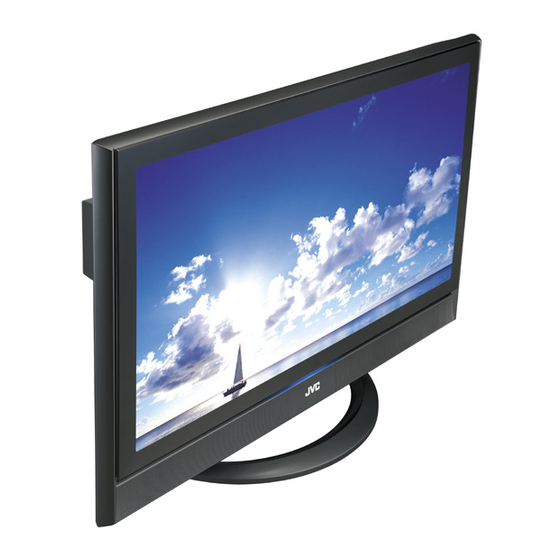
JVC LT-37M60BU Service Manual
Wide lcd panel television
Hide thumbs
Also See for LT-37M60BU:
- Instructions manual (20 pages) ,
- Instructions manual (40 pages) ,
- Manual (41 pages)
Table of Contents
Advertisement
Quick Links
Download this manual
See also:
Instruction Manual
www.freeservicemanuals.info
SERVICE MANUAL
11
YA360
2005
LT-37M60BU, LT-37M60BU
LT-37M60ZU, LT-37M60ZU
1
PRECAUTION. . . . . . . . . . . . . . . . . . . . . . . . . . . . . . . . . . . . . . . . . . . . . . . . . . . . . . . . . . . . . . . . . . . . . . . . . 1-3
2
SPECIFIC SERVICE INSTRUCTIONS . . . . . . . . . . . . . . . . . . . . . . . . . . . . . . . . . . . . . . . . . . . . . . . . . . . . . . 1-6
3
DISASSEMBLY . . . . . . . . . . . . . . . . . . . . . . . . . . . . . . . . . . . . . . . . . . . . . . . . . . . . . . . . . . . . . . . . . . . . . . 1-11
4
ADJUSTMENT . . . . . . . . . . . . . . . . . . . . . . . . . . . . . . . . . . . . . . . . . . . . . . . . . . . . . . . . . . . . . . . . . . . . . . . 1-18
5
TROUBLESHOOTING . . . . . . . . . . . . . . . . . . . . . . . . . . . . . . . . . . . . . . . . . . . . . . . . . . . . . . . . . . . . . . . . . 1-25
WIDE LCD PANEL TELEVISION
TABLE OF CONTENTS
COPYRIGHT © 2005 Victor Company of Japan, Limited
Digitized in Heiloo Netherland
4/19/2017
,
/P
/P
BASIC CHASSIS
FL2
No.YA360
2005/11
Advertisement
Chapters
Table of Contents

Related Manuals for JVC LT-37M60BU


Summary of Contents for JVC LT-37M60BU
-
Page 1: Table Of Contents
SERVICE MANUAL WIDE LCD PANEL TELEVISION YA360 2005 LT-37M60BU, LT-37M60BU LT-37M60ZU, LT-37M60ZU BASIC CHASSIS TABLE OF CONTENTS PRECAUTION............... . . 1-3 SPECIFIC SERVICE INSTRUCTIONS . - Page 2 www.freeservicemanuals.info 4/19/2017 SPECIFICATION Items Contents Dimensions ( W × H × D ) 92.6 cm × 68.9 cm × 29.7 cm [Included stand] 92.6 cm × 63.1 cm × 10.8 cm [TV only] Mass 26.2 kg [Included stand] 20.7 kg [TV only] Power Input AC110V - AC240 V, 50 Hz / 60 Hz Power Consumption...
-
Page 3: Precaution
www.freeservicemanuals.info 4/19/2017 SECTION 1 PRECAUTION SAFETY PRECAUTIONS (1) The design of this product contains special hardware, (6) Isolation Check (Safety for Electrical Shock Hazard) many circuits and components specially for safety After re-assembling the product, always perform an purposes. For continued protection, no changes should be isolation check on the exposed metal parts of the cabinet made to the original design unless authorized in writing by (antenna terminals, video/audio input and output terminals,... - Page 4 www.freeservicemanuals.info 4/19/2017 INSTALLATION 1.2.1 HEAT DISSIPATION 1.2.3 INSTALLATION REQUIREMENTS If the heat dissipation vent behind this unit is blocked, cooling To ensure safety in an emergency such as an earthquake, and efficiency may deteriorate and temperature inside the unit will to prevent accidents, ensure that measures are taken to prevent rise.
- Page 5 www.freeservicemanuals.info 4/19/2017 HANDLING LCD PANEL 1.3.1 PRECAUTIONS FOR TRANSPORTATION 1.3.2 OPTICAL FILTER (ON THE FRONT OF THE LCD PANEL) When transporting the unit, pressure exerted on the internal LCD (1) Avoid placing the unit under direct sunlight over a panel due to improper handling (such as tossing and dropping) prolonged period of time.
-
Page 6: Specific Service Instructions
3D CINEMA SOUND ZOOM You can enjoy sounds with a widerambience. This function can change the screen size according to the picture aspect ratio. MAIN DIFFERENCE LIST Item LT-37M60BU LT-37M60BU/P LT-37M60ZU LT-37M60ZU/P ← ← CABINET COLOUR SILVER / BLACK BLACK ←... - Page 7 4/19/2017 HOW TO IDENTIFY MODELS LT-37M60BU and LT-37M60ZU: "AE" is added to the serial No. after at the Rating label. LT-37M60BU/P and LT-37M60ZU/P: "PE" is added to the serial No. after at the Rating label. MODEL No. LT-37M60BU LT-37M60ZU SERIAL NO.
- Page 8 www.freeservicemanuals.info 4/19/2017 TECHNICAL INFORMATION 2.6.1 LCD PANEL This unit uses the flat type panel LCD (Liquid Crystal Display) panel that occupies as little space as possible, instead of the conventional CRT (Cathode Ray Tube), as a display unit. Since the unit has the two polarizing filter that are at right angles to each other, the unit adopts "normally black" mode, where light does not pass through the polarizing filter and the screen is black when no voltage is applied to the liquid crystals.
- Page 9 www.freeservicemanuals.info 4/19/2017 2.6.2 MAIN CPU PIN FUNCTION [IC7501 : DIGITAL SIGNAL PWB] Pin name Function Pin name Function Test purpose I/O Program ROM data for main CPU Test purpose I/O Program ROM data for main CPU Test purpose I/O Program ROM data for main CPU Test purpose VSS33 P2.8...
- Page 10 www.freeservicemanuals.info 4/19/2017 2.6.3 SUB (CHASSIS) CPU PIN FUNCTION [IC7001 : DIGITAL SIGNAL PWB] Pin name Function Pin name Function LB_PRO Not used BS_TXD Not used : Data transmission for digital tuner communication P_MU Picture muting [Muting = H] BS_RXD Not used : Data receive for digital tuner communication JP_CSB Not used (NC) Not used (NC)
-
Page 11: Disassembly
www.freeservicemanuals.info 4/19/2017 SECTION 3 DISASSEMBLY DISASSEMBLY PROCEDURE CAUTION AT DISASSEMBLY: • Be sure to perform the SYSTEM SETTEING, at the end of the procedure. • Make sure that the power cord is disconnected from the outlet. • Pay special attention not to break or damage the parts. •... - Page 12 www.freeservicemanuals.info 4/19/2017 JACK COVER STAND COVER JACK COVER STAND TUNER BASE SHIELD COVER FAN BRACKET REGULATOR PWB REAR COVER POWER PWB RECEIVER PWB POWER CORD SIDE SHIELD CASE TOP SHIELD CASE POWER CORD HOLDER RECEIVER PWB PANEL I/F PWB BRACKET CONNECTOR PWB ANALOG SIGNAL PWB PANEL I/F PWB...
- Page 13 www.freeservicemanuals.info 4/19/2017 3.1.11 REMOVING THE SPEAKER (Fig.2) 3.1.15 REMOVING THE LCD PANEL UNIT (Fig.2) • Remove the STAND. • Remove the STAND. • Remove the REAR COVER. • Remove the REAR COVER. (1) Remove the 6 screws [A], then remove the SPEAKER (L /R). •...
- Page 14 www.freeservicemanuals.info 4/19/2017 CARD SHIELD CARD BASE CARD PWB MAIN BASE CARD PWB BRACKET BOTTOM FRAME TOP FRAME SPEAKER FRONT LED PWB SPEAKER LED LENS FRONT PANEL FRONT Fig.2 1-14 (No.YA360) Digitized in Heiloo Netherland...
- Page 15 www.freeservicemanuals.info 4/19/2017 MEMORY IC REPLACEMENT • This model uses the memory IC. • This memory IC stores data for proper operation of the video and drive circuits. • When replacing, be sure to use an IC containing this (initial value) data. 3.2.1 MEMORY IC REPLACEMENT PROCEDURE 1.
- Page 16 www.freeservicemanuals.info 4/19/2017 3.2.3 SETTINGS OF FACTORY SHIPMENT 3.2.3.1 BUTTON OPERATION 3.2.3.2 REMOTE CONTROL DIRECT OPERATION Setting item Setting position Setting item Setting position POWER CHANNEL CHANNEL VOLUME VOLUME ZOOM PANORAMIC TV/AV 3D SOUND 3.2.3.3 REMOTE CONTROL MENU OPERATION (1) PICTURE (4) FEATURES Setting item Setting position...
- Page 17 www.freeservicemanuals.info 4/19/2017 REPLACEMENT OF CHIP COMPONENT 3.3.1 CAUTIONS (1) Avoid heating for more than 3 seconds. (2) Do not rub the electrodes and the resist parts of the pattern. (3) When removing a chip part, melt the solder adequately. (4) Do not reuse a chip part after removing it. 3.3.2 SOLDERING IRON (1) Use a high insulation soldering iron with a thin pointed end of it.
-
Page 18: Adjustment
www.freeservicemanuals.info 4/19/2017 SECTION 4 ADJUSTMENT ADJUSTMENT PREPARATION ADJUSTMENT ITEMS (1) There are 2 ways of adjusting this TV : One is with the VIDEO CIRCUIT REMOTE CONTROL UNIT and the other is the • 625i A-D OFFSET adjustment conventional method using adjustment parts and •... - Page 19 www.freeservicemanuals.info 4/19/2017 4.5.3 DESCRIPTION OF STATUS DISPLAY (5) SETTING ITEM NAME Setting item name are displayed. The setting item numbers to SETTINGITEM No. SETTING ITEM SETTING VALUE (DATA) be displayed are listed below. Item No. Setting item S001 to S039 Video system setting S001 PREPARE S001 PREPARE...
- Page 20 www.freeservicemanuals.info 4/19/2017 INITIAL SETTING VALUES IN THE SERVICE MODE • Perform fine-tuning based on the "initial values" using the remote control when in the Service mode. • The "initial values" serve only as an indication rough standard and therefore the values with which optimal display can be achieved may be different from the default values.
- Page 21 www.freeservicemanuals.info 4/19/2017 Item No. Item name Variable range Setting value Item No. Item name Variable range Setting value D020 SYH CON 00 - 3F D070 (Not display) 00 - FF D021 SYH CONF 00 - 01 D071 (Not display) 00 - FF D022 SC CON 00 - 3F...
- Page 22 www.freeservicemanuals.info 4/19/2017 Item No. Item name Variable range Setting value Item No. Item name Variable range Setting value D120 (Not display) 00 - FF D170 (Not display) 00 - FF D121 (Not display) 00 - FF D171 (Not display) 00 - FF D122 (Not display) 00 - FF...
- Page 23 www.freeservicemanuals.info 4/19/2017 ADJUSTMENT PROCEDURE 4.7.1 VIDEO CIRCUIT Measuring Item Test point Adjustment part Description instrument 625i Remote [1.ADJUST] (1) Receive a 625i component ramp pattern signal. A-D OFFSET control unit S001: PREPARE (2) Set PICTURE MODE to "STANDARD". (Adjustment setting mode change) (3) Set ZOOM to "FULL".
- Page 24 www.freeservicemanuals.info 4/19/2017 Measuring Item Test point Adjustment part Description instrument SUB SCREEN Remote [1.ADJUST] (1) Set PICTURE MODE to "STANDARD". A-D OFFSET control unit S001: PREPARE (2) Set ZOOM" to "FULL". (Adjustment setting mode change) (3) Set COLOUR TEMP. to "NORMAL". Signal (4) Set MULTI SCREEN to "2 pictures".
-
Page 25: Troubleshooting
www.freeservicemanuals.info 4/19/2017 SECTION 5 TROUBLESHOOTING SELF CHECK FEATURE 5.1.5 POINTS TO NOTE WHEN USING THE SELF CHECK FEATURE 5.1.1 OUTLINE In addition to circuit failures (abnormal operation), the following This unit comes with the "Self check" feature, which checks the cases may also be iagnosed as "Abnormal"... - Page 26 www.freeservicemanuals.info 4/19/2017 5.1.6 DETAILS Self check is performed for the following items: < Page 1 of screen > Diagnosis Detection item Display Detection content Detection timing signal (line) Low bias line short Confirmation of operation of the low bais LB_PRO Detection starts 3 seconds after the protection (2.5V / 3.3V / 5V / 9V) protection circuit.
- Page 27 www.freeservicemanuals.info 4/19/2017 < Page 2 of screen > Diagnosis Detection item Display Detection content Detection timing signal (line) Fan lock Not used. Abnormal of operation of Not used. PANEL Abnormal rise of Not used. temperature in PANEL Abnormal rise of Not used.
- Page 28 www.freeservicemanuals.info 4/19/2017 Victor Company of Japan, Limited AV & MULTIMEDIA COMPANY DISPLAY CATEGORY 12, 3-chome, Moriya-cho, Kanagawa-ku, Yokohama-city, Kanagawa-prefecture, 221-8528, Japan (No.YA360) Printed in Japan Digitized in Heiloo Netherland...
-
Page 29: Parts List
www.freeservicemanuals.info 4/19/2017 PARTS LIST CAUTION The parts identified by the symbol are important for the safety . Whenever replacing these parts, be sure to use specified ones to secure the safety. The parts not indicated in this Parts List and those which are filled with lines --- in the Parts No. columns will not be supplied. P.W. - Page 30 EXPLODED VIEW -1 ..............................3-5 EXPLODED VIEW PARTS LIST -2 ..........................3-6 EXPLODED VIEW -2 ..............................3-7 PRINTED WIRING BOARD PARTS LIST [LT-37M60BU, LT-37M60ZU] ..............3-8 ANALOG SIGNAL P.W. BOARD ASS'Y (SFL-1116A-U2) ................. 3-8 CONNECTOR P.W. BOARD ASS'Y (SFL-4114A-U2) ..................3-12 FRONT CONTROL P.W.
-
Page 31: Using P.w. Board & Remote Control Unit
4/19/2017 USING P.W. BOARD & REMOTE CONTROL UNIT P.W.B ASS'Y No. P.W.B ASS'Y name LT-37M60BU LT-37M60BU/P LT-37M60ZU LT-37M60ZU/P ← ← ← ANALOG SIGNAL P.W.B SFL-1116A-U2 ← ← ← CONNECTOR P.W.B SFL-4114A-U2 ← ← ← FRONT CONTROL P.W.B SFL-7111A-U2 ←... -
Page 32: Exploded View Parts List -1
Ref.No. Part No. Part Name Description Local LC21923-001A-U JACK COVER (x2) 102 LC12450-002A-U REAR COVER GA10134-001A-U STAND ASSY Inc.103A/103B LT-37M60BU,LT-37M60BU/P GA10134-002A-U STAND ASSY Inc.103A/103B LT-37M60ZU,LT-37M60ZU/P 103A GA30094-001A-U STAND COVER 103B GA30081-002A-U CABLE COVER QYSPSPD5014MA SCREW M5 x 14mm(x4) -
Page 33: Exploded View -1
www.freeservicemanuals.info 4/19/2017 EXPLODED VIEW -1 103A 103B SHIELD COVER FAN BRACKET SIDE SHIELD CASE TOP SHIELD CASE RECEIVER PWB BRACKET PANEL I/F PWB BRACKET (No.YA360)3-5 Digitized in Heiloo Netherland... -
Page 34: Exploded View Parts List -2
CORE FILTER LC41913-004A-C SPEAKER ASSY LEFT LC40226-005A-H SPACER (x6) LC41913-003A-C SPEAKER ASSY RIGHT 158 LC12449-006A-U FRONT PANEL ASSY LT-37M60BU,LT-37M60BU/P 158 LC12449-004B-U FRONT PANEL ASSY LT-37M60ZU,LT-37M60ZU/P LC33125-001B-HK LED LENS 160 LC33197-005B-0K CARD BASE ASSY QQR0491-001 FERRITE CORE (x2) -
Page 35: Exploded View -2
www.freeservicemanuals.info 4/19/2017 EXPLODED VIEW -2 CARD SHIELD MAIN BASE CARD PWB BRACKET BOTTOM FRAME TOP FRAME FRONT (No.YA360)3-7 Digitized in Heiloo Netherland... -
Page 36: Printed Wiring Board Parts List [Lt-37M60Bu, Lt-37M60Zu]
4/19/2017 PRINTED WIRING BOARD PARTS LIST [LT-37M60BU, LT-37M60ZU] ANALOG SIGNAL P.W. BOARD ASS'Y Ref No. Part No. Part Name Description Local (SFL-1116A-U2) D903 PTZ11B-X Z DIODE Ref No. Part No. Part Name Description Local D904 PTZ6.8B-X Z DIODE D905... - Page 37 www.freeservicemanuals.info 4/19/2017 Ref No. Part No. Part Name Description Local Ref No. Part No. Part Name Description Local C315 NCB31HK-103X C CAPACITOR 0.01uF 50V K C864 NCB31HK-103X C CAPACITOR 0.01uF 50V K C316 NCB31HK-103X C CAPACITOR 0.01uF 50V K C865 NDC31HJ-560X C CAPACITOR 56pF 50V J...
- Page 38 www.freeservicemanuals.info 4/19/2017 Ref No. Part No. Part Name Description Local Ref No. Part No. Part Name Description Local C6006 NEHL1HM-105X E CAPACITOR 1uF 50V M C6676 NDC31HJ-561X C CAPACITOR 560pF 50V J C6007 QETN1AM-108Z E CAPACITOR 1000uF 10V M C6677 NDC31HJ-561X C CAPACITOR 560pF 50V J...
- Page 39 www.freeservicemanuals.info 4/19/2017 Ref No. Part No. Part Name Description Local Ref No. Part No. Part Name Description Local R556 NRSA63J-101X MG RESISTOR 100Ω 1/16W J R902 NRSA63J-182X MG RESISTOR 1.8kΩ 1/16W J R572 NRSA63J-0R0X MG RESISTOR 0Ω 1/16W J R903 NRSA63J-152X MG RESISTOR 1.5kΩ...
-
Page 40: Connector P.w. Board Ass'y (Sfl-4114A-U2)
www.freeservicemanuals.info 4/19/2017 Ref No. Part No. Part Name Description Local Ref No. Part No. Part Name Description Local R6409 NRSA63J-103X MG RESISTOR 10kΩ 1/16W J R6680 NRSA63J-103X MG RESISTOR 10kΩ 1/16W J R6423 NRSA63J-332X MG RESISTOR 3.3kΩ 1/16W J R6684 NRSA63J-104X MG RESISTOR 100kΩ... -
Page 41: Front Control P.w. Board Ass'y (Sfl-7111A-U2)
www.freeservicemanuals.info 4/19/2017 Ref No. Part No. Part Name Description Local Ref No. Part No. Part Name Description Local R8713 NRSA63J-331X MG RESISTOR 330Ω 1/16W J R4301 NRSA63J-472X MG RESISTOR 4.7kΩ 1/16W J R8714 NRSA63J-103X MG RESISTOR 10kΩ 1/16W J R4302 NRSA63J-472X MG RESISTOR 4.7kΩ... - Page 42 www.freeservicemanuals.info 4/19/2017 Ref No. Part No. Part Name Description Local Ref No. Part No. Part Name Description Local C1301 NCF31CZ-104X C CAPACITOR 0.1uF 16V Z R1203 NRSA63J-103X MG RESISTOR 10kΩ 1/16W J C1402 NCF31CZ-104X C CAPACITOR 0.1uF 16V Z R1204 NRSA63J-103X MG RESISTOR 10kΩ...
-
Page 43: Power P.w. Board Ass'y (Sfl-9039A-U2)
www.freeservicemanuals.info 4/19/2017 Ref No. Part No. Part Name Description Local Ref No. Part No. Part Name Description Local R2044 NRSA63J-330X MG RESISTOR 33Ω 1/16W J Q9541 UN2212-X DIGI TRANSISTOR R2046 NRSA63J-101X MG RESISTOR 100Ω 1/16W J Q9602 2SB1188/QR/-W TRANSISTOR R2047 NRSA63J-330X MG RESISTOR 33Ω... - Page 44 www.freeservicemanuals.info 4/19/2017 Ref No. Part No. Part Name Description Local Ref No. Part No. Part Name Description Local C9520 NCB31HK-331X C CAPACITOR 330pF 50V K R9536 NRSA02J-0R0X MG RESISTOR 0Ω 1/10W J C9541 QECQ1VM-128 E CAPACITOR 1200uF 35V M R9541 NRSA63J-684X MG RESISTOR 680kΩ...
-
Page 45: Regulator P.w. Board Ass'y (Sfl-9138A-U2)
www.freeservicemanuals.info 4/19/2017 REGULATOR P.W. BOARD ASS'Y (SFL-9138A-U2) DIGITAL SIGNAL P.W. BOARD ASS'Y (SFL0D234A-U2) Ref No. Part No. Part Name Description Local Ref No. Part No. Part Name Description Local IC9801 MP1593DN-X IC9841 MP1593DN-X IC0401 SN74AHCT1G32V-X IC IC9861 MP1593DN-X IC1001 TC90A92AFG IC9881 LM393DR-X IC1002... - Page 46 www.freeservicemanuals.info 4/19/2017 Ref No. Part No. Part Name Description Local Ref No. Part No. Part Name Description Local Q7206 UN2213-X DIGI TRANSISTOR C1033 NCB31HK-103X C CAPACITOR 0.01uF 50V K Q7207 UN2113-X TRANSISTOR C1034 NDC31HJ-390X C CAPACITOR 39pF 50V J Q7208 UN2113-X TRANSISTOR C1035...
- Page 47 www.freeservicemanuals.info 4/19/2017 Ref No. Part No. Part Name Description Local Ref No. Part No. Part Name Description Local C3040 NCB31CK-104X C CAPACITOR 0.1uF 16V K C4915 NCB31HK-103X C CAPACITOR 0.01uF 50V K C3041 NDC31HJ-101X C CAPACITOR 100pF 50V J C4916 NCB31HK-103X C CAPACITOR 0.01uF 50V K...
- Page 48 www.freeservicemanuals.info 4/19/2017 Ref No. Part No. Part Name Description Local Ref No. Part No. Part Name Description Local C7548 NEHL0GM-227X E CAPACITOR 220uF 4V M R0340 NRSA63J-182X MG RESISTOR 1.8kΩ 1/16W J C7550 NCB31HK-103X C CAPACITOR 0.01uF 50V K R0341 NRSA63J-472X MG RESISTOR 4.7kΩ...
- Page 49 www.freeservicemanuals.info 4/19/2017 Ref No. Part No. Part Name Description Local Ref No. Part No. Part Name Description Local R3018 NRSA02J-3R3X MG RESISTOR 3.3Ω 1/10W J R3531 NRSA63J-510X MG RESISTOR 51Ω 1/16W J R3019 NRSA02J-3R3X MG RESISTOR 3.3Ω 1/10W J R3533 NRSA63J-510X MG RESISTOR 51Ω...
- Page 50 www.freeservicemanuals.info 4/19/2017 Ref No. Part No. Part Name Description Local Ref No. Part No. Part Name Description Local R7006 NRSA63J-101X MG RESISTOR 100Ω 1/16W J R7208 NRSA63J-102X MG RESISTOR 1kΩ 1/16W J R7007 NRSA63J-101X MG RESISTOR 100Ω 1/16W J R7209 NRSA63J-152X MG RESISTOR 1.5kΩ...
-
Page 51: Receiver P.w. Board Ass'y (Sfl0F204A-U2)
www.freeservicemanuals.info 4/19/2017 Ref No. Part No. Part Name Description Local Ref No. Part No. Part Name Description Local RA3506 NRZ0040-510X NET RESISTOR 51Ω 1/16W J x4 L9002 NRSA02J-0R0X MG RESISTOR 0Ω 1/10W J RA3508 NRZ0080-510X NET RESISTOR 51Ω 1/16W J L9201 NQL71EM-150X COIL... -
Page 52: Panel I/F P.w. Board Ass'y (Sfl0H001A-U2)
www.freeservicemanuals.info 4/19/2017 Ref No. Part No. Part Name Description Local Ref No. Part No. Part Name Description Local C3518 NCB31HK-222X C CAPACITOR 2200pF 50V K R3563 NRSA63J-103X MG RESISTOR 10kΩ 1/16W J C3519 NCB31CK-105X C CAPACITOR 1uF 16V K R3564 NRSA63J-103X MG RESISTOR 10kΩ... - Page 53 www.freeservicemanuals.info 4/19/2017 Ref No. Part No. Part Name Description Local Ref No. Part No. Part Name Description Local C5044 NCB31HK-102X C CAPACITOR 1000pF 50V K R5061 NRSA63J-103X MG RESISTOR 10kΩ 1/16W J C5046 NCB31HK-104X C CAPACITOR 0.1uF 50V K R5063 NRSA63J-103X MG RESISTOR 10kΩ...
-
Page 54: Printed Wiring Board Parts List [Lt-37M60Bu/P, Lt-37M60Zu/P]
4/19/2017 PRINTED WIRING BOARD PARTS LIST [LT-37M60BU LT-37M60ZU ANALOG SIGNAL P.W. BOARD ASS'Y Ref No. Part No. Part Name Description Local (SFL-1116A-U2) Q0102 2SA1022/BC/-X TRANSISTOR REFER TO PARTS LIST IN PAGE 3-8 FOR THIS P.W. BOARD. Q0104 2SA1022/BC/-X TRANSISTOR... - Page 55 www.freeservicemanuals.info 4/19/2017 Ref No. Part No. Part Name Description Local Ref No. Part No. Part Name Description Local C0114 NCB31CK-104X C CAPACITOR 0.1uF 16V K C1081 NCB31HK-103X C CAPACITOR 0.01uF 50V K C0115 NCB31CK-104X C CAPACITOR 0.1uF 16V K C1082 NCB31HK-103X C CAPACITOR 0.01uF 50V K...
- Page 56 www.freeservicemanuals.info 4/19/2017 Ref No. Part No. Part Name Description Local Ref No. Part No. Part Name Description Local C3129 NDC31HJ-470X C CAPACITOR 47pF 50V J C6523 NCB11AK-106X C CAPACITOR 10uF 10V K C3191 NCB31HK-103X C CAPACITOR 0.01uF 50V K C7001 NCB31AK-105X C CAPACITOR 1uF 10V K...
- Page 57 www.freeservicemanuals.info 4/19/2017 Ref No. Part No. Part Name Description Local Ref No. Part No. Part Name Description Local R0132 NRSA63J-472X MG RESISTOR 4.7kΩ 1/16W J R1017 NRSA63J-101X MG RESISTOR 100Ω 1/16W J R0133 NRSA63J-0R0X MG RESISTOR 0Ω 1/16W J R1018 NRSA63J-332X MG RESISTOR 3.3kΩ...
- Page 58 www.freeservicemanuals.info 4/19/2017 Ref No. Part No. Part Name Description Local Ref No. Part No. Part Name Description Local R3070 NRSA63J-0R0X MG RESISTOR 0Ω 1/16W J R4061 NRSA63J-0R0X MG RESISTOR 0Ω 1/16W J R3071 NRSA63J-0R0X MG RESISTOR 0Ω 1/16W J R4064 NRSA63J-0R0X MG RESISTOR 0Ω...
- Page 59 www.freeservicemanuals.info 4/19/2017 Ref No. Part No. Part Name Description Local Ref No. Part No. Part Name Description Local R7070 NRSA63J-0R0X MG RESISTOR 0Ω 1/16W J R7588 NRSA63J-221X MG RESISTOR 220Ω 1/16W J R7077 NRSA63J-0R0X MG RESISTOR 0Ω 1/16W J R7590 NRSA63J-101X MG RESISTOR 100Ω...
-
Page 60: Receiver P.w. Board Ass'y (Sfl0F204A-U2)
Local 2AA070311 BATTERY COVER PACKING PARTS LIST Ref.No. Part No. Part Name Description Local GA10002-070A-U PACKING CASE GA10027-028A-U EURO LABEL LT-37M60BU,LT-37M60BU/P GA10027-041A-U EURO LABEL LT-37M60ZU GA10027-042A-U EURO LABEL LT-37M60ZU/P GA10133-001A-U CUSHION ASSY 4pcs in 1set GA10026-003A-U FORM BAG RM-C1811H-2C... -
Page 61: Packing
www.freeservicemanuals.info 4/19/2017 PACKING (No.YA360)3-33 Digitized in Heiloo Netherland... - Page 62 4/19/2017 SCHEMATIC DIAGRAMS WIDE LCD PANEL TELEVISION YA360 2005 LT-37M60BU, LT-37M60BU LT-37M60ZU, LT-37M60ZU CD-ROM No.SML200511 BASIC CHASSIS No.YA360 COPYRIGHT © 2005 Victor Company of Japan, Limited Digitized in Heiloo Netherland 2005/11...
- Page 63 4/19/2017 LT-37M60BU, LT-37M60BU/P, LT-37M60ZU, LT-37M60ZU/P STANDARD CIRCUIT DIAGRAM NOTE ON USING CIRCUIT DIAGRAMS 1.SAFETY Type No indication : Ceramic capacitor The components identified by the symbol and shading are : Metalized mylar capacitor critical for safety. For continued safety replace safety ciritical : Polypropylene capacitor components only with manufactures recommended parts.
- Page 64 CARD PWB PATTERN ..........................2-79 FRONT CONTROL PWB PATTERN ......................2-81 FRONT LED PATTERN ..........................2-81 VOLTAGE CHATRS................... 2-83 WAVEFORMS .................... 2-86 USING P.W. BOARD P.W.B ASS’Y name LT-37M60BU LT-37M60BU/P LT-37M60ZU LT-37M60ZU/P ANALOG SIGNAL P.W. BOARD SFL-1116A-U2 SFL-4114A-U2 CONNECTOR P.W. BOARD SFL-7111A-U2 FRONT CONTROL P.W.
-
Page 65: Semiconductor Shapes
www.freeservicemanuals.info 4/19/2017 SEMICONDUCTOR SHAPES TRANSISTOR BOTTOM VIEW FRONT VIEW TOP VIEW CHIP TR E C B E C B ( G ) ( D ) ( S ) BOTTOM VIEW FRONT VIEW TOP VIEW CHIP IC TOP VIEW (No.YA360)2-3 Digitized in Heiloo Netherland... - Page 66 www.freeservicemanuals.info 4/19/2017 2-4(No.YA360) Digitized in Heiloo Netherland...
-
Page 67: Wiring Diagram
www.freeservicemanuals.info 4/19/2017 WIRING DIAGRAM CONNECTOR PWB ANALOG SIGNAL PWB 1CV1 CN0011 CN1011 TU3001 ANALOG TUNER CN0012 CN1012 LCD PANEL UNIT RECEIVER PWB CN0002 CN0001 CN5181 PANEL I/F PWB CARD PWB CN5001 CN5002 CN003 CN002 CN001 LCD PANEL UNIT CN000W CN8CV2 CN0LV2 CN8CV1 CN003... -
Page 68: Block Diagram
www.freeservicemanuals.info 4/19/2017 BLOCK DIAGRAM ANALOG SIGNAL PWB RECEIVER PWB IC3501 IC6521 HEAD SPEAKER(L) MULTI SOUND PROCESS IC3503 BBE/SURROUND/AOUDIO CONTROL PHONE IC6621 LIPL LIPL J7001 IC6001 COMPARAT IC6661 TU3001 LIPR LIPR SIF_OUT BASS DEMOD. VOLUME SURROUND IC6551 IC6552 DIGITAL U/V FRONTEND SOUND VOL1 TONE... -
Page 69: Circuit Diagrams
www.freeservicemanuals.info 4/19/2017 CIRCUIT DIAGRAMS RECEIVER PWB CIRCUIT DIAGRAM SHEET 1 SFL- SFL- SFP- 0F203A 0F204A 0F205A RECEIVER PWB ASS'Y OLLC08303 OLLC08303 OLLC08116 QGA2001C6 CNF00A OPEN OPEN -03X SFL0F204A-U2 QGA2001F6 QGA2001F6 CNF01A OPEN -03X -03X QAU0428 TU3001 OPEN OPEN -001 QAU0428 QAU0428 TU3002 OPEN... - Page 70 www.freeservicemanuals.info 4/19/2017 ANALOG SIGNAL PWB CIRCUIT DIAGRAM (1/5) [AV SW BLOCK] SHEET 2 SHEET4 OPEN OPEN SHEET3 CN00UV CN00UA J2007 QNZ0561-001 PC_HS PC_VS C511 C512 ANALOG SIGNAL PWB ASS'Y (1/5) OPEN OPEN C2601 PC_DET C513 C514 PC_R C591 C592 C593 C594 C595 R596...
- Page 71 www.freeservicemanuals.info 4/19/2017 ANALOG SIGNAL PWB CIRCUIT DIAGRAM (2/5) [SUB DECORD BLOCK] SHEET 3 FRONT LED PWB ASSS'Y CN100U (SHEET21) SHEET5 SHEET4 SHEET4 SHEET2 CN000U GQA1501C5-09W SHEET2 SHEET2,4,5,6 SHEET4 STB_5V BS_A3V BS_A5V CN0011 QGF0508F1-50X SSM3K17FU-X R402 CN0012 BS_A9V Q402 QGF0508F1-50X BS_A5V LIP_R BS_A9V TEXT_FB1...
- Page 72 www.freeservicemanuals.info 4/19/2017 ANALOG SIGNAL PWB CIRCUIT DIAGRAM (3/5) [COMPONENT SW BLOCK] SHEET 4 PC_VS SHEET2 PC_HS Y204 Y203 NRSA02J-0R0X Y202 NRSA02J-0R0X Y201 R336 5.6k C349 YUVSWY1 R219 SYNC1_IN R220 R334 2.2k Q307 C223 R335 2.2k C338 OPEN C211 C207 R208 YUVSWPB1 C212 R209...
- Page 73 www.freeservicemanuals.info 4/19/2017 ANALOG SIGNAL PWB CIRCUIT DIAGRAM (4/5) [AUDIO BLOCK] SHEET 5 ANALOG SIGNAL PWB ASS'Y (4/5) SFL-1116A-U2 IC6201 PQ20WZ11-X AU_+VCC VCC12V Y6202 Y6201 D6201 1SS355-X C6204 C6621 R6201 R6621 R6622 R6203 3300p 5.6K AU_+VCC R6624 C6202 C6201 R6205 C6205 R6623 0.01 0.01...
- Page 74 www.freeservicemanuals.info 4/19/2017 ANALOG SIGNAL PWB CIRCUIT DIAGRAM (5/5) SHEET 6 RECEIVER PWB ASS'Y CNF01A (SHEET1) CN000A QGA2001C2-03V Y909 OPEN Y910 OPEN Y921 OPEN Y922 OPEN GND_S5 GND2 CN00UB SCL3B5 SHEET2,3,4,5 OPEN SDA3B5 BS5V BS9V UK_12V BS_ABT30 ILA5V STB_5V STB3.3V BS_A9V BS_A5V Q901 BA90BC0FP-X...
-
Page 75: Digital Signal Pwb Circuit Diagram
OPEN OPEN OUT-A OPEN IN-C C1558 C1559 IN-B OPEN OPEN DIGITAL SIGNAL PWB ASS'Y (1/11) OUT-C IC1534 SFL0D234A-U2 [LT-37M60BU, LT-37M60ZU] C1562 C1561 OPEN C1563 C1564 OPEN OPEN OPEN OPEN LCA10557-67A (SFL-0D234A) [LT-37M60BU/P, LT-37M60ZU/P] c10374002b010_1004_10/12_0.0 (No.YA360)2-21 2-22(No.YA360) Digitized in Heiloo Netherland... - Page 76 C0305 C0306 R0315 R0328 Q0310 OPEN HN1C01F/Y/-X R0342 4.7K Q0306 R0343 Q0303 R0311 4.7k AGND R0345 4.7k DIGITAL SIGNAL PWB ASS'Y (2/11) R0344 4.7k Q0311 SFL0D234A-U2 [LT-37M60BU, LT-37M60ZU] AGND LCA10557-67A (SFL-0D234A) [LT-37M60BU/P, LT-37M60ZU/P] c10374002b001_1004_1/12_0.0 (No.YA360)2-23 2-24(No.YA360) Digitized in Heiloo Netherland...
- Page 77 N.C. N.C. 3DHS N.C. 3DVS N.C. HREF N.C. C1086 SHEET16 0.01 A92RES A92RES N.C. N.C. DIGITAL SIGNAL PWB ASS'Y (3/11) R1025 SFL0D234A-U2 [LT-37M60BU, LT-37M60ZU] LCA10557-67A (SFL-0D234A) [LT-37M60BU/P, LT-37M60ZU/P] C1084 C1085 0.01 0.01 DGND c10374002b002_1004_2/12_0.0 (No.YA360)2-25 2-26(No.YA360) Digitized in Heiloo Netherland...
- Page 78 DIGITAL SIGNAL PWB ASS'Y (4/11) OPEN R2157 Q2101 OPEN OPEN BSOUTGND R2150 R2130 OPEN OPEN CNSH_GND AGND DGND R2128 OPEN BS_COUT SFL0D234A-U2 [LT-37M60BU, LT-37M60ZU] R2129 R2132 OPEN OPEN R2106 Q2102 OPEN OPEN LCA10557-67A (SFL-0D234A) [LT-37M60BU/P, LT-37M60ZU/P] AGND c10374002b009_1004_9/12_0.0 (No.YA360)2-27 2-28(No.YA360) Digitized in Heiloo Netherland...
- Page 79 4/19/2017 DIGITAL SIGNAL PWB CIRCUIT DIAGRAM (5/11) [DET CORE] SHEET 11 DIGITAL SIGNAL PWB ASS'Y (5/11) SFL0D234A-U2 SD_DQS0 SD_DQS1 [LT-37M60BU, LT-37M60ZU] RA3540 RA3542 RA3516 RA3518 C3506 LCA10557-67A (SFL-0D234A) 2.2/6.3 C3507 C3532 0.47/16 C3530 2.2/6.3 C3125 C3124 OPEN [LT-37M60BU/P, LT-37M60ZU/P]...
- Page 80 /QR/-X /QR/-X RA4008 RA4010 RA4012 NRZ0034-101W NRZ0034-101W NRZ0034-101W RA4007 RA4009 RA4011 NRZ0034-101W NRZ0034-101W NRZ0034-101W DIGITAL SIGNAL PWB ASS'Y (6/11) SFL0D234A-U2 [LT-37M60BU, LT-37M60ZU] LCA10557-67A (SFL-0D234A) [LT-37M60BU/P, LT-37M60ZU/P] RA4005 RA4006 OPEN OPEN RA4003 RA4004 OPEN OPEN RA4001 RA4002 OPEN OPEN NOTE : Refer to the part list for the part number of IC4003 and IC4004.
- Page 81 SCL3A OPEN R6564 OPEN SDA3A R6565 R6547 DGND R6542 DGND R6548 R6559 OPEN Q6502 R6549 OPEN DGND DIGITAL SIGNAL PWB ASS'Y (7/11) SHEET17 SHEET14,16 SHEET12 SFL0D234A-U2 [LT-37M60BU, LT-37M60ZU] SHEET12,16 LCA10557-67A (SFL-0D234A) [LT-37M60BU/P, LT-37M60ZU/P] c10374002b007_1004_7/12_0.0 (No.YA360)2-33 2-34(No.YA360) Digitized in Heiloo Netherland...
- Page 82 DIGITAL SIGNAL PWB ASS'Y (8/11) K6001 OPEN K6002 OPEN K6003 OPEN K6004 OPEN SFL0D234A-U2 [LT-37M60BU, LT-37M60ZU] K6005 OPEN K6006 OPEN K6007 OPEN LCA10557-67A (SFL-0D234A) [LT-37M60BU/P, LT-37M60ZU/P] K6008 OPEN K6021 OPEN K6020 OPEN K6019 OPEN R6060 OPEN OPEN K6009 OPEN AGND K6010...
- Page 83 4/19/2017 DIGITAL SIGNAL PWB CIRCUIT DIAGRAM (9/11) [RE MICON] SHEET 15 DIGITAL SIGNAL PWB ASS'Y (9/11) SFL0D234A-U2 [LT-37M60BU, LT-37M60ZU] LCA10557-67A (SFL-0D234A) [LT-37M60BU/P, LT-37M60ZU/P] SHEET16,17 WAKE WAKE SHEET11 CARD_DET CARD_DET OSDB5 OSDB5 STB3.3V OSDB4 SHEET10,12,17 R7681 OPEN DD_OSDVS OSDB4 IC7602...
- Page 84 DIGITAL SIGNAL PWB CIRCUIT DIAGRAM (10/11) [SH MICON] SHEET 16 NOTE : Refer to the part list for the part number of IC7002. DIGITAL INPUT BLOCK STB3.3V DIGITAL SIGNAL PWB ASS'Y (10/11) IC7003 SN74LVC2G241T-X 1/OE SFL0D234A-U2 [LT-37M60BU, LT-37M60ZU] LCA10557-67A (SFL-0D234A) AGND OLLC07697 OLLC07697 OLLC07697 OLLC07697 OLLC07697...
- Page 85 DGND DIGITAL SIGNAL PWB ASS'Y (11/11) SFL0D234A-U2 [LT-37M60BU, LT-37M60ZU] SHEET8 for DIGITAL IN SHEET9 SHEET10 NOTE : Refer to the part list for the part number of IC7504. SHEET7 LCA10557-67A (SFL-0D234A) [LT-37M60BU/P, LT-37M60ZU/P] c10374002b012_1004_12/12_0.0 (No.YA360)2-41 2-42(No.YA360) Digitized in Heiloo Netherland...
- Page 86 www.freeservicemanuals.info 4/19/2017 PANEL I/F PWB CIRCUIT DIAGRAM SHEET 18 POWER PWB ASS'Y (2/2) DIGITAL SINGAL PWB ASS'Y (7/11) CN000K (SHEET23) CN0LV2 (SHEET13) CN5002 CN5001 QGA2001F6-04X VDD3 VCC3 QGA0504F1-31X K5103 K5101 L5102 NQLC8CM-150X PANEL I/F PWB ASS'Y VDD18 L5101 NQLC8CM-150X K5104 R5112 IC5101 D5114...
-
Page 87: Connector Pwb Circuit Diagram
www.freeservicemanuals.info 4/19/2017 CONNECTOR PWB CIRCUIT DIAGRAM SHEET 19 CN0001 CN0001 CN1011 QGF0508F1-50X QGF0508C1-50W QGF0508F1-50X SCL3B SDA3B TEXT_FB1 TEXT_FB1 TEXT_FG1 TEXT_FG1 TEXT_FR1 TEXT_FR1 REC_RSV SUB_CCD DIN_PHOTO SCL_3A SDA_3A MSP_RST CN00UD LIP_RST CN40UB QGA2001F2-07V EE_CDS OPEN QGA2001C2-06V EE_CDS AFT1 MECA_SW 2.5V POW_LED M_MUTE OPEN R4811... -
Page 88: Front Control Pwb Circuit Diagram
www.freeservicemanuals.info 4/19/2017 FRONT CONTROL PWB CIRCUIT DIAGRAM SHEET 20 FRONT LED PWB CIRCUIT DIAGRAM SHEET 21 R8714 R8716 R8715 R8713 R8712 R8717 R8711 CN100U QGA1501C5-09W POWER_LED Q8708 Q8707 CN100R QGA1501C5-10W DIMMED_LED R8725 STB5V KEY1 S7707 C7701 QSW1131-001Z FUNC D8712 Q8704 Q8702 KEY2 Q8701... - Page 89 www.freeservicemanuals.info 4/19/2017 POWER PWB CIRCUIT DIAGRAM (1/2) SHEET 22 OPEN CN000D QGA7901C1-02 Y9013 OPEN POWER PWB ASS'Y (1/2) C9002 Y9014 QFZ9072-105 F9001 OPEN QMF5AD2-6R3-J1 R9001 R9202 QRZ9046-105Z OPEN CN00PW LF9001 LF9002 LF9003 QQR1514-001 QQR1467-001 QQR1514-001 SFL-9039A-U2 QGA7901C1-02 POWER CORD VA9001 R9201 QAF0060-621 AC110V-AC240V,...
- Page 90 www.freeservicemanuals.info 4/19/2017 POWER PWB CIRCUIT DIAGRAM (2/2) SHEET 23 LCD PANEL UNIT LCD PANEL UNIT CN000P QGA2001C6-10X CN000Q QGA2001C6-10X CN0CV3 CARD PWB ASS'Y (2/2) QGA1501C5-03W K9505 CN8CV3 NQR0499-002X POWER PWB ASS'Y (2/2) GND5 (SHEET26) GND6 GND4 Q9608 CN000Y 2SB1188/QR/-W SFL-9039A-U2 OPEN D9301 OPEN...
-
Page 91: Regulator Pwb Circuit Diagram
www.freeservicemanuals.info 4/19/2017 REGULATOR PWB CIRCUIT DIAGRAM SHEET 24 D9801 OPEN MP1593DN-X IC9801 R9801 C9807 OPEN 0.0033 R9802 NCB31HK-332X C9801 OPEN OPEN R9804 5.6k R9810 GND2 GND2 C9802 C9805 OPEN 0.0022 NCB31HK-222X GND2 GND2 Q9801 L9802 R9803 2SC3928A/QR/-X D9805 NQL98EM-150X PTZ6.8B-X D9803 MA111-X L9801... -
Page 92: Card Pwb Circuit Diagram
www.freeservicemanuals.info 4/19/2017 CARD PWB CIRCUIT DIAGRAM (1/2) SHEET25 CONNECTOR SIGNAL PWB ASS'Y CN0CV2 (SHEET19) 3.3V 3.3V RST_ETC IC1202 SN74LVC1G04V-X IC1005 RPI-352 R1231 R1012 LD[0-15] R1232 LA[0-21]_RSEL C1205 IC1203 SN74LVC1G08V-X R1013 C1206 3.3V R1233 CN8CV2 3.3V QGA1501F4-04W SHEET25 CARD_POW IC1201 3.3V K1501 Q1201 3.3V... - Page 93 www.freeservicemanuals.info 4/19/2017 CARD PWB CIRCUIT DIAGRAM (2/2) SHEET26 Y/PB/PR[0-7]_DCLK Y/PB/PR[0-7]_DCLK FOR ADJUST 3.3V SHEET25 CN2004 QGA1201C2-06X 3.3V K2003 K2004 CORE CORE K2002 CORE C2004 NCB31HK-102X HSYNC R2007 4.7k HSYNC C2003 VSYNC NCJ41CK-226X-U R2008 4.7k VSYNC PCLK2X R2009 4.7k PCLK2X R2040 YUV7 R2010 4.7k...
-
Page 94: Pattern Diagrams
www.freeservicemanuals.info 4/19/2017 PATTERN DIAGRAMS RECEIVER PWB PATTERN [PARTS SIDE] RECEIVER PWB PATTERN [SOLDER SIDE] R3043 R3014 R3015 C3574 IC3506 IC3507 R3578 R3582 R3573 C3113 R3040 IC3510 R3574 R3039 R3583 IC3508 IC3104 C3571 R3516 R3575 C3114 R3584 R3038 R3579 R3577 IC3509 C3115 R3585 D3104... -
Page 95: Analog Signal Pwb Pattern
www.freeservicemanuals.info 4/19/2017 ANALOG SIGNAL PWB PATTERN [SOLDER SIDE] R2058 R2057 C2053 R2056 R2171 J2003 J2005 R2054 R2172 C2052 R2055 J2007 R2053 R2052 R2051 J2001 J2002 R2603 J2004 R2606 C2452 R2602 R2454 D2606 D2603 D2601 R2455 R2456 D2602 Q2453 Q2452 C2453 R2457 R2458 C6545 R6534... - Page 96 www.freeservicemanuals.info 4/19/2017 ANALOG SIGNAL PWB PATTERN [PARTS SIDE] J2004 D2204 J2002 J2001 J2007 J2003 C2206 R2201 R2101 D2001 C2153 C2201 C2109 C2108 C2107 D2105 D2106 D2103 D2102 R2106 R2151 C2011 C2010 C2009 C2008 D2004 D2107 D2005 D2002 D2003 C2401 C2402 C2306 C2308 C2304...
-
Page 97: Digital Signal Pwb Pattern
www.freeservicemanuals.info 4/19/2017 DIGITAL SIGNAL PWB PATTERN [SOLDER SIDE] CN0C1 CN0MM D8002 J001 C7531 Q8003 CN0MDR D8010 D8009 D8005 CN0DVI C4923 C7506 J7002 L7512 C7505 J7001 C6022 C7504 IC7501 Q7203 Q7204 C4982 R7124 Q8002 C7530 D8008 D8007 D8004 D8003 D8022 D8001 D7502 Q7205 C6119... - Page 98 www.freeservicemanuals.info 4/19/2017 DIGITAL SIGNAL PWB PATTERN [PARTS SIDE] J7001 J7002 CN0MI CN0C2 CN0DVI CN0MDR D6110 D6109 D6106 D6105 D6102 Q6102 R7710 C6021 LC7502 C8054 R7019 R7569 R6127 Q8005 R7046 IC7003 R6050 R7161 RA7503 RA7502 IC8003 R7083 IC6003 C6023 D6107 D6104 D6103 D6101 Q6001...
-
Page 99: Panel I/F Pwb Pattern
www.freeservicemanuals.info 4/19/2017 PANEL I/F PWB PATTERN [SOLDER SIDE] PANEL I/F PWB PATTERN [PARTS SIDE] D5121 D5122 TP5903 R5181 C5187 R5182 C5181 R5183 C5127 R5184 K5182 R5185 C5188 TP5913 C5121 D5123 R5188 TP5181 C5128 TP5182 R5125 K5172 R5124 D5124 R5126 C5182 R5073 R5071 TP5902... -
Page 100: Connector Pwb Pattern
www.freeservicemanuals.info 4/19/2017 CONNECTOR PWB PATTERN [SOLDER SIDE] Y4003 C4210 C4211 CONNECTOR PWB PATTERN [PARTS SIDE] (No.YA360)2-71 2-72(No.YA360) Digitized in Heiloo Netherland... -
Page 101: Power Pwb Pattern
www.freeservicemanuals.info 4/19/2017 POWER PWB PATTERN [SOLDER SIDE] R9002 C9151 C9911 R9631 R9629 R9640 R9641 R9658 R9660 R9633 D9609 R9151 R9635 CN0006 CN0007 Q9153 R9158 R9944 Q9606 R9153 R9940 C9606 K9503 D9152 R9156 R9154 R9001 R9938 R9937 F9001 R9917 R9619 D9606 Q9603 R9915 K9509... - Page 102 www.freeservicemanuals.info 4/19/2017 POWER PWB PATTERN [PARTS SIDE] R9002 C9151 C9911 L9903 R9001 F9001 VA9001 CN0007 C9608 CN0006 FC9002 FC9001 R9302 L9901 C9550 C9014 C9545 C9143 IC9931 R9301 Y9012 IC9901 C9901 C9142 R9142 R9141 K9001 C9553 L9541 Y9011 L9904 C9012 C9912 C9302 D9542 D9546...
-
Page 103: Regulator Pwb Pattern
www.freeservicemanuals.info 4/19/2017 REGULATOR PWB PATTERN [SOLDER SIDE] C9866 C9848 C9841 R9808 R9828 R9849 R9831 R9842 R9869 C9831 C9826 R9809 R9829 C9823 D9863 Q9801 Q9821 D9802 C9846 C9883 C9847 R9844 R9824 C9849 R9883 C9825 C9844 R9882 D9882 C9867 R9884 FRONT C9882 C9804 R9866 R9812... -
Page 104: Card Pwb Pattern
www.freeservicemanuals.info 4/19/2017 CARD PWB PATTERN [SOLDER SIDE] CARD PWB PATTERN [PARTS SIDE] R1508 R1507 RA1009 R1247 R1237 R1509 R1506 R1214 R1239 R1504 R1235 R1003 R1510 RA1010 R1218 IC1501 R1203 C1010 K1501 R1217 R1204 D1203 CN1003 R1501 R1502 C1204 C1004 R1053 R1052 C1003 R1243... -
Page 105: Front Control Pwb Pattern
www.freeservicemanuals.info 4/19/2017 FRONT CONTROL PWB PATTERN [SOLDER SIDE] S7707 S7704 S7703 S7702 S7701 S7705 S7706 R7017 R7018 C7701 J7001 C7703 R7701 R7702 R7704 C7702 R7703 C7012 L7001 C7011 FRONT CONTROL PWB PATTERN [PARTS SIDE] S7706 S7705 S7701 S7702 S7703 S7704 S7707 CN100R FRONT LED PWB PATTERN [SOLDER SIDE]... - Page 106 www.freeservicemanuals.info 4/19/2017 VOLTAGE CHARTS <RECIEVER PWB> [P.2-9 - P.2-10] [P.2-19 - P.2-20] [P.2-39 - P.2-40] MODE MODE MODE MODE MODE MODE MODE MODE MODE MODE MODE MODE MODE MODE MODE MODE MODE MODE MODE MODE MODE MODE MODE DC (V) DC (V) DC (V) DC (V)
- Page 107 www.freeservicemanuals.info 4/19/2017 <CONNECTOR PWB> <REGULATOR PWB> <PANEL I/F PWB> [P.2-51 - P.2-52] [P.2-57 - P.2-58] [P.2-47 - P.2-48] MODE MODE MODE MODE MODE MODE MODE MODE MODE MODE MODE MODE DC ( V ) DC ( V ) DC ( V ) DC ( V ) DC ( V ) DC ( V )
-
Page 108: Waveforms
www.freeservicemanuals.info 4/19/2017 WAVEFORMS RECEIVER PWB ANALOG SIGNAL PWB (1/5) (SHEET1) (SHEET2) TU3001-16 IC501-41 IC501-44 IC501-49 IC501-53 IC501-56 IC501-63 0.8 Vp-p 2.1 Vp-p 2.1 Vp-p 2.1 Vp-p 2.1 Vp-p 2.1 Vp-p 1.0 Vp-p ANALOG SIGNAL PWB (2/5) (SHEET3) IC801-1 IC801-3 IC801-5 IC801-9 IC801-11 IC801-21... - Page 109 www.freeservicemanuals.info 4/19/2017 Victor Company of Japan, Limited AV & MULTIMEDIA COMPANY DISPLAY CATEGORY 12, 3-chome, Moriya-cho, Kanagawa-ku, Yokohama-city, Kanagawa-prefecture, 221-8528, Japan (No.YA360) Printed in Japan Digitized in Heiloo Netherland...
Need help?
Do you have a question about the LT-37M60BU and is the answer not in the manual?
Questions and answers