Table of Contents
Advertisement
Advertisement
Table of Contents

Related Manuals for LAWO V_pro8

Summary of Contents for LAWO V_pro8
- Page 1 V_pro8 Installation & Operation Manual Version: 1.0/2 Edition: 17 November 2012...
- Page 2 All entries in this document have been thoroughly checked; however no guarantee for correctness can be given. Lawo AG cannot be held responsible for any misleading or incorrect information provided throughout this manual.
-
Page 3: Table Of Contents
Table of Contents Table of Contents Welcome Important Safety Instructions Overview Introducing the V_Pro8 Feature Summary Signal Flow Block Diagram Licensing Controls, Connectors & Indicators Front Panel Overview Rear Panel Overview Installation & Configuration Computer System Requirements Installation Checklist Packing List... - Page 4 Table of Contents SDI In MADI In SDI Out MADI Out Quad Split Timing Settings Technical Data Glossary V1.0/2 V_pro8 Manual...
-
Page 5: Welcome
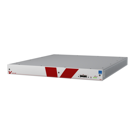
Welcome Welcome Welcome to the V_pro8, Lawo's compact and cost-efficient solution for connecting and converting video and audio signals: Front View Rear View This documentation is designed for users and technicians, and covers installation and operation. You can access more information by registering at www.lawo.de... -
Page 6: Important Safety Instructions
Servicing unprotected powered devices may only be carried out by qualified service personnel at their own risk. The following instructions MUST be observed: o NEVER touch bare wires or circuitry. o Use insulated tools ONLY. o DO NOT touch metal semi-conductor casings as they can bear high voltages. V1.0/2 V_pro8 Manual... - Page 7 Defective Parts/Modules Warning The V_pro8 contains no user-serviceable parts. Therefore DO NOT open the devices other than to perform the procedures described in this manual. In the event of a hardware defect, please send the system component to your local service representative together with a detailed description of the fault.
-
Page 8: Overview
Overview Overview This chapter provides an overview of the V_pro8 and its key features: Introducing the V_pro8 Feature Summary Signal Flow Block Diagram Licensing V1.0/2 V_pro8 Manual... -
Page 9: Introducing The V_Pro8
Introducing the V_Pro8 Introducing the V_Pro8 The V_pro8 is a large de-embedder, embedder with routing plus video/audio processing and monitoring capabilities. It decodes different video and audio signals, and then transforms them from one format to another. By combining flexible signal routing with video and audio processing, the pro8... -
Page 10: Feature Summary
Audio PPM Metering - for every audio input and output channel. Status Monitoring - for an overview of SDI and MADI inputs. Quad Split Monitoring The MV (MultiView) output, available on BNC or DisplayPort connectors, provides local monitoring of up to 4 SDI inputs or outputs simultaneously. V1.0/2 V_pro8 Manual... - Page 11 Redundant power supplies - two independent power supplies are fitted to each unit; one main and one redundant. Redundant MADI links - front & rear panel connections operate in parallel to offer redundant in/out links. Redundant network connection - two LAN ports can connect to the control network. V_pro8 Manual V1.0/2...
-
Page 12: Signal Flow Block Diagram
Overview Signal Flow Block Diagram Signal Flow Block Diagram V1.0/2 V_pro8 Manual... -
Page 13: Licensing
Monitoring Package - Quad split monitoring, Waveform monitoring (YUV & RGB) and the Vectorscope Format Conversion 1 - one channel of video format conversion. Format Conversion 1 - two channels of video format conversion. In Version 1.0, licenses are pre-installed at the factory. V_pro8 Manual V1.0/2... -
Page 14: Controls, Connectors & Indicators
Indicate the status of the two internal power supplies: Green = power supply is active. Off = power supply is inactive (no mains input or internal supply is faulty). Part Number The part number of your unit. V1.0/2 V_pro8 Manual... -
Page 15: Rear Panel Overview
AC POWER IN 1 & 2 mains AC power inputs on IEC (Auto sensing 100-240V VAC, 50/60Hz). Only one supply is required to operate the system. For redundancy, connect both supplies, each to a separate AC mains circuit. V_pro8 Manual V1.0/2... -
Page 16: Installation & Configuration
Installation & Configuration Installation & Configuration This chapter covers the hardware installation of the V_pro8, and the configuration of your control computer, network and other settings: Computer System Requirements Installation Checklist Packing List Adaptor Installation Frame Installation Grounding & Power... -
Page 17: Computer System Requirements
Web Browser: Mozilla Firefox, Google Chrome or Apple Safari (V6.0). Note that the Status -> MADI menu is slow when using Safari. Screen Resolution: >= 1440 x 900 is recommended, in order to view the full operating window without scrolling. V_pro8 Manual V1.0/2... -
Page 18: Installation Checklist
Open a web browser session. Check the software revision and, if necessary, update your unit. Connect the remaining video, audio and reference signals. Configure the reference settings for your installation. The rest of this chapter covers the steps in more detail. V1.0/2 V_pro8 Manual... -
Page 19: Packing List
Two IEC power cables (country-specific) Two 19" rack-mounting brackets for the frame Two SFP Optical Fibre Transceivers for MADI ports Documentation on CD Check the contents, and in the event of any transport damage, please contact your local Lawo representative. V_pro8 Manual V1.0/2... -
Page 20: Adaptor Installation
MADI ports 1 & 2 at both the front and rear of the unit. The SFP transceivers are hot-pluggable. To install, push each adaptor into the rectangular MADI slot. Press gently and firmly until the adaptor locks into position. V1.0/2 V_pro8 Manual... -
Page 21: Frame Installation
The unit is fitted with six fans inside, and ventilation holes on the left and right. Proper operation is guaranteed between temperatures of 0° C and 40° C and a maximum relative humidity of <= 90% non-condensing. Warning DO NOT obstruct the ventilation holes as to do so will prevent efficient cooling. V_pro8 Manual V1.0/2... -
Page 22: Grounding & Power
Country-specific mains adaptors will be supplied with the system. When running with multiple mains supplies, make sure that both circuits lie on the same ground potential. Otherwise, an internal bridge of two ground wires will lead to a ground loop! V1.0/2 V_pro8 Manual... -
Page 23: Powering On
Flashing Yellow = network activity. Red = system error. If the STATUS LED is red, then try powering the unit off and on. For further assistance, please contact your local Lawo representative or email service@Lawo.de. PSU 1 and PSU 2 LEDs Green = power supply is active. -
Page 24: Network Connection
Each unit provides two LAN ports on the rear panel. In Version 1.0, these may be used for a main and redundant network connection. In a future software release, the second LAN port may be used to connect RAVENNA (audio over IP), or other control devices such as the Lawo mc /Nova 73 or VSM. -
Page 25: Tcp/Ip Configuration
Therefore, you will need to manually configure the TCP/IP settings on each unit. To do this, connect your computer directly, open a web browser session and use the Settings -> Network menu to adjust the IP Address of LAN 1 and/or LAN 2. V_pro8 Manual V1.0/2... - Page 26 The following screenshots demonstrate how to configure the TCP/IP settings of your computer’s Network Interface card in Windows 7 and Mac OS X: Windows 7: Mac OS X: You can find further information from www.microsoft.com or www.apple.com. V1.0/2 V_pro8 Manual...
-
Page 27: Web Browser Control
Note that video is monitored for the SDI Out, and not SDI In. Therefore, you will only see incoming video signals, if the video channel routing is set to as SDI In 1 to SDI Out 1, SDI In 2 to SDI Out 2, etc. See Signal Routing for details. V_pro8 Manual V1.0/2... - Page 28 However, if you are working without signals present, and you close and ignore the "connection lost" message, be aware that you are NOT controlling parameters within the pro8! V1.0/2 V_pro8 Manual...
-
Page 29: Troubleshooting The Browser Connection
PING test to check your network communication. Firewall or Antivirus Software - some software may interfere with web browser communication. Try disabling your Firewall and/or Antivirus to eliminate them as the cause of the problem. V_pro8 Manual V1.0/2... - Page 30 If the ping command is successful, then the result will show that the Sent packets have been successfully Received. This confirms that the network communication is working. If your browser connection continues to fail, check the URL address and/or disable any Firewall or Antivirus software. V1.0/2 V_pro8 Manual...
-
Page 31: Software Update
Installation & Configuration Software Update Software Update Having installed the unit and established web browser communication, it is a good idea to check the software revision and, if necessary, perform a software update. Settings -> Software Update for details. V_pro8 Manual V1.0/2... -
Page 32: Signal Connections
Installation & Configuration Signal Connections Signal Connections Having dealt with both power network (LAN), the remaining front and rear panel connections are for video, audio and external reference signals: SDI Connections MV Out Connections MADI Connections External Reference Connections V1.0/2 V_pro8 Manual... - Page 33 8 x SDI inputs and 8 x SDI outputs on BNC connectors. Each SDI connection carries one digital video and 16 embedded audio channels. A wide range of 10-bit 3G, HD and SD video standards are supported, please see Technical Data. V_pro8 Manual V1.0/2...
- Page 34 1 x BNC (3G) - in a future release, HD-SDI will be supported. 1 x DisplayPort. Once connected, Quad Split monitoring is configured from the user interface, see the Quad Split menu. On the external display, each monitor window provides the following information: V1.0/2 V_pro8 Manual...
- Page 35 MADI input (front or rear) from the user interface.) An LED for each port indicates the status: Green = MADI link is active. Flashing Red = MADI link is asynchronous. Off = no connection or MADI link is invalid. V_pro8 Manual V1.0/2...
- Page 36 OUT - video reference output. Use this connector to feed the system's video reference, as selected in the user interface, to an external device. WK - wordclock out. (In a future release, this bi-directional connection will be set to either wordclock in or out from the user interface). V1.0/2 V_pro8 Manual...
-
Page 37: Reference Settings
In Version 1.0, the audio reference is ALWAYS set to Follow Video. This means that the system is clocked from a single reference source. In a future software release, you will be able to clock video and audio signals independently. V_pro8 Manual V1.0/2... -
Page 38: Operation (Web Browser Control)
The first part of this chapter covers the user interface and common tasks: Operating Principles Signal Routing Delay Other Processing Saving Your Settings The second part covers each menu in detail: The Main Menus: Summary Status SDI In MADI In SDI Out MADI Out Quad Split Timing Settings V1.0/2 V_pro8 Manual... -
Page 39: Operating Principles
Operation (Web Browser Control) Operating Principles Operating Principles Opening a Web Browser Session Menu Selection & Navigation Expanding Menus Channel Selection & Parameter Control Multiple Channel Selection V_pro8 Manual V1.0/2... - Page 40 Note that video is monitored for the SDI Out, and not SDI In. Therefore, you will only see incoming video signals, if the video channel routing is set to as SDI In 1 to SDI Out 1, SDI In 2 to SDI Out 2, etc. See Signal Routing for details. V1.0/2 V_pro8 Manual...
- Page 41 However, if you are working without signals present, and you close and ignore the "connection lost" message, be aware that you are NOT controlling parameters within the pro8! V_pro8 Manual V1.0/2...
- Page 42 SDI In main menu. The left hand side of the information area can display different options. Click on the green button beside PPM to choose from Timecode, Vectorscope, WFM (WaveForm Monitor) or PPM Meter. See SDI Out: Display Options. V1.0/2 V_pro8 Manual...
- Page 43 Click on a sub menu to access a different set of parameters - for example, Delay: Click on one of the inner main menus - Out 1 to Out 8 - to access a different SDI output. You can use this to quickly switch between SDI outputs and compare parameters. V_pro8 Manual V1.0/2...
- Page 44 To select a different main menu, click on it (if you can see it). Or, collapse the expanded view, by clicking on either of the blue X buttons: The menu bar returns to its normal size. V1.0/2 V_pro8 Manual...
- Page 45 Delay (sub menu). If you now switch between SDI In and SDI Out from the main menu bar, both sub menu selections are set to Delay. This makes it very fast to switch between input and output delay parameters. V_pro8 Manual V1.0/2...
- Page 46 The channel buttons change colour as follows: Light Blue = selected channels. Green (or Blue) = unselected SDI (or MADI) channels. Dark Blue = a valid channel selection (you will see this colour as you hover your mouse over the buttons). V1.0/2 V_pro8 Manual...
- Page 47 If delay is enabled, then the delay bar is clear (Black or Orange). If delay is disabled, then the delay bar is greyed out. If channels which already have delay are adjusted, then any offsets are retained. For more details on input and output delay, see Delay. V_pro8 Manual V1.0/2...
- Page 48 Click directly on the channel select button: To select all available channels Click on the "T" formed by the black dividing lines between the video and audio channels (SDI): Or, click on the central dividing line of the audio channels (MADI): V1.0/2 V_pro8 Manual...
- Page 49 Click on the black dividing line in between the channels you wish to select - for example, between SDI Groups A and B: Or click on the grey Group A, Group B, Group C, Group D indicators to select all the audio channels in an SDI group. V_pro8 Manual V1.0/2...
- Page 50 IP address. In these instances: Click on the left or right arrow buttons to highlight the correct set of digits (in red): Use the on-screen numeric keyboard to enter a new value. Click on Enter to confirm the data entry. V1.0/2 V_pro8 Manual...
-
Page 51: Signal Routing
MADI Input channels 1 to 64 are assigned to MADI Output channels 1 to 64 for both MADI ports. This means that as soon as you connect video to your SDI inputs, you can preview these signals from the login screen SDI Out main menu (providing you haven't altered the default video channel assignments). V_pro8 Manual V1.0/2... - Page 52 In our example, SDI Out 1 is currently assigned from the video and audio channels of SDI In 1. By selecting the MADI 1 01-32 sub menu, we can access the first 32 audio channels from MADI port 1. V1.0/2 V_pro8 Manual...
- Page 53 Green = SDI (video and audio channels) Blue = MADI channels Dark Blue = a valid channel selection (you will see this colour as you hover your mouse over the Input Table or drag and drop onto the Output area). V_pro8 Manual V1.0/2...
- Page 54 To assign all available channels (e.g. from SDI In to SDI Out) Click on the "T" formed by the black dividing lines between the video and audio channels, and drag and drop onto the first target channel: V1.0/2 V_pro8 Manual...
- Page 55 9 to assign the eight channels to SDI channels 9 to 16. If you select more source channels than there are targets (for example, all 32 MADI channels), then the first channels from the selection are assigned. V_pro8 Manual V1.0/2...
-
Page 56: Delay
If delay is enabled, then the delay bar is clear (Black or Orange). If delay is disabled, then the delay bar is greyed out. If channels which already have delay are adjusted, then any offsets are retained. V1.0/2 V_pro8 Manual... - Page 57 If the output channel is routed from an input channel with delay, then you will see both the input and output delay values: The maximum delay per channel (input + output) cannot exceed 8 frames for video channels or 320ms for audio channels. V_pro8 Manual V1.0/2...
-
Page 58: Video & Audio Processing
Sample Rate Conversion (for all SDI in & out) - see SDI In -> FSY & SRC. Variable Delay (per channel) - see Delay. Test tone Generator (per SDI embedder) - see SDI Out -> Ch.ID & Pattern. V1.0/2 V_pro8 Manual... -
Page 59: Saving Settings
The current settings are saved each time you power off the unit. When you power on, these settings are recalled. This ensures that the unit comes back as it was last used for fast recovery from a loss of power. V_pro8 Manual V1.0/2... -
Page 60: The Main Menus: Summary
Timing Pos. - adjust the timing position of the pro 8, globally, with respect to the video reference. This sub menu also contains the Reference Settings, where you can select the system's video and audio reference. Ref Out - options for the video reference output. V1.0/2 V_pro8 Manual... - Page 61 Network - check the TCP/IP settings and Mac Address for the LAN 1 and LAN 2 network ports. You can change the IP address of each port from here. Software Update - check or update the software version of the pro8. V_pro8 Manual V1.0/2...
-
Page 62: Status
Use this menu to interrogate your SDI inputs, MADI links or pro8 system. The upper area of the operating window is unused. Status information is displayed in the lower half of the screen when you select a sub menu: V1.0/2 V_pro8 Manual... - Page 63 PCM or Dolby E, etc. In our example, the green circle indicates that signal is present on at least one channel within SDI Group A. Timecode - embedded timecode (VITC 1, VITC 2 and LTC). Click on a field to open a pop-up with further information: Video Format: V_pro8 Manual V1.0/2...
- Page 64 Operation (Web Browser Control) Status Payload: Video Index: AFD: Embedded Audio: V1.0/2 V_pro8 Manual...
- Page 65 Operation (Web Browser Control) Status Timecode: V_pro8 Manual V1.0/2...
- Page 66 To interrogate the status of the MADI audio channels, select either MADI 1 I/O or MADI 2 I/O from the sub menus: If signal is present on a MADI input or output, then a green circle appears - in our example, audio is present on MADI port 2, Outputs 1&2 and 17&18. V1.0/2 V_pro8 Manual...
- Page 67 Temperature - various readings from the unit's temperature sensors. See Frame Installation for recommended operating temperatures. Fan Controller 1 & 2 - the fan speeds for each fan group. License - the license status for each of the pro8 options. V_pro8 Manual V1.0/2...
- Page 68 Sample Rate Conversion) for the selected SDI input. Note that video is not monitored for the SDI Inputs, so you will not see video thumbnails or a preview. To preview your incoming video, select SDI Out and change video channel routing accordingly. V1.0/2 V_pro8 Manual...
- Page 69 Operation (Web Browser Control) SDI In SDI In -> Delay This sub menu adjusts input delay for the de-embedded video and audio channels. For full details, see Delay. V_pro8 Manual V1.0/2...
- Page 70 In our example, frame sync for the video channel and SRC for audio channels 1 to 12 are enabled; SRC is disabled on channels 13 to 16; channels 13 to 16 are selected (light blue select buttons). V1.0/2 V_pro8 Manual...
- Page 71 The meter scale is dBFS, and includes a peak hold indicator (green) and overload flag (red) if audio levels reach 0dBFS. The peak hold indicator clears automatically after a few seconds. The lower half of the screen can be used to adjust input Delay. For details, see Delay. V_pro8 Manual V1.0/2...
- Page 72 - output delay (for each video and embedded audio channel). ANC Data - ancillary data such as embedded timecode, AFD and audio. Ch. ID & Pattern - insertion of channel ID and timecode into the video channel, and test tone into all embedded audio channels. V1.0/2 V_pro8 Manual...
-
Page 73: Display Options
Displays the three embedded timecode streams (VITC 1, VITC 2 and LTC): Vectorscope Vectorscope monitoring of the video channel. The X-Y plot compares the amplitude of different colour components (R = Red, Mg = Magenta, B = Blue, Cy = Cyan, G = Green, Yl = Yellow): V_pro8 Manual V1.0/2... - Page 74 Peak Programme Metering for the 16 embedded audio channels. The meter scale is dBFS, and includes a peak hold indicator (green) and overload flag (red) if audio levels reach 0dBFS. The peak hold indicator clears automatically after a few seconds. V1.0/2 V_pro8 Manual...
- Page 75 If there is no audio assigned to an output channel, then you will see the text not present on the audio bargraph. Or, if the embedded audio group has been disabled (from SDI Out -> ANC), then you will see Group disabled: V_pro8 Manual V1.0/2...
- Page 76 The SDI In and MADI In sub menus are used to change the signal routing for the selected SDI output. For full details, see Signal Routing. Note that the embedded audio groups - A, B, C and D - can be enabled or disabled from the menu. V1.0/2 V_pro8 Manual...
- Page 77 To change the format: Click on the Converter button to choose a new output format. Click on Aspect Ratio to select a new preset. Then select the Status On button to apply the conversion - the Output field updates accordingly. V_pro8 Manual V1.0/2...
- Page 78 4:3 Center Cut - an incoming 4:3 image is unchanged. 16:9 Letterbox - an incoming 16:9 image is sized to fit onto a 4:3 screen. The proportions of the image are retained, but black bars appear at the top and bottom of the screen. V1.0/2 V_pro8 Manual...
- Page 79 This option is also known as "Barn Doors". Remember to set the Status to On, to apply your new Converter and Aspect Ratio settings. V_pro8 Manual V1.0/2...
- Page 80 Click and drag on the outer colour wheel to adjust the Hue - you can use the inner wheel, which remains static, for reference. To reset a parameter, click on its Default button. Or, click between the buttons to reset a parameter block: V1.0/2 V_pro8 Manual...
- Page 81 Corr. For example, to assist with RGB camera matching. The method of control is very similar, except that this time you may adjust the Luminance (Y) and individual colour (RGB) components: YUV Corr for details on operating the controls. V_pro8 Manual V1.0/2...
- Page 82 If the incoming video signal doesn't match the auto phaser range, then the timing of the input signal must be modified (externally to the pro8). Or, if this is not possible, the pro8's frame synchroniser can be enabled to solve the problem, but note that this introduces a one video frame delay. V1.0/2 V_pro8 Manual...
- Page 83 Input - takes timecode from the assigned SDI input stream. Start - enables a "free run" mode: o First, click on the Timecode Start box to enter the start timecode (for help, see Data Entry). o Then click on Start to set the timecode running. V_pro8 Manual V1.0/2...
- Page 84 Enable the Group A to D buttons to embed audio groups into the SDI output. In our example, only Groups A and B will be embedded. Note that your selections are reflected in the PPM metering output: V1.0/2 V_pro8 Manual...
- Page 85 Select either of the Audio Tone buttons (blue = on; grey = off). Only one button may be selected at a time: 1kHz (-18dB) - routes a 1 kHz sine wave to all 16 embedded audio channels. 400Hz (-18dB) - routes a 400 Hz sine wave to all 16 embedded audio channels. V_pro8 Manual V1.0/2...
- Page 86 The meter scale is dBFS, and includes a peak hold indicator (green) and overload flag (red) if audio levels reach 0dBFS. The peak hold indicator clears automatically after a few seconds. The lower half of the screen can be used to adjust signal routing or delay, see Signal Routing Delay. V1.0/2 V_pro8 Manual...
- Page 87 On the lower right you will see the current assignments for the selected Monitor (e.g. Monitor 1). Note that the coloured outline (yellow) is duplicated on the external display. This provides easy identification for each of the four monitor positions. The lower left is used to select SDI inputs or outputs for assignment. V_pro8 Manual V1.0/2...
- Page 88 Or, to assign a new pair of audio audio channels only, drag and drop the audio channels onto the appropriate bargraph meters: After each new assignment, the Sources summary updates. For more information on connecting the Quad Split output, or to see what is shown on the external display, see MV (MultiView) OUT. V1.0/2 V_pro8 Manual...
- Page 89 If the picture is not locked (for example, you have disconnected the video reference signal), then the horizontal turquoise bar moves from left to right, and the pixel/line fields fluctuate: V_pro8 Manual V1.0/2...
- Page 90 Click and drag the inner timing wheel to adjust the pixel position. Click and drag the outer timing wheel to adjust the line position. The timing position of the pro8 moves. You will see the new position compared to that of the reference source on the XY display: V1.0/2 V_pro8 Manual...
- Page 91 Out. If the Video Ref is set to an external reference such as Analog, then the system automatically detects the format and defines the available Format conversion options. Audio Ref. - selects the audio reference signal (in our example, Follow Video). V_pro8 Manual V1.0/2...
- Page 92 In Version 1.0, the audio reference is ALWAYS set to Follow Video. This means that the system is clocked from a single reference source. In a future software release, you will be able to lock audio independently, either to an external Wordclock signal or to free run. V1.0/2 V_pro8 Manual...
- Page 93 50Hz format or derivatives such as 1080 25p: You can change which output format options are black (selectable) by changing the Video Reference and/or Format field in the Timing -> Timing Pos menu. V_pro8 Manual V1.0/2...
- Page 94 Network - check the TCP/IP settings and Mac Address for the LAN 1 and LAN 2 network ports. You can change the IP address and subnet mask of each port from here. Software Update - check the software version of the pro8 or perform a software update. V1.0/2 V_pro8 Manual...
- Page 95 Click on the current IP Address to open the pop-up selector. Click on the right arrow button to highlight the correct set of digits; use the numeric keyboard to enter a new value and click Enter. The IP Address field updates. V_pro8 Manual V1.0/2...
- Page 96 The LAN port settings are reset. Providing your computer's Network Interface Card is within the same IP range, the browser automatically reconnects, and you are returned to the login screen. Both LAN ports will be disconnected for a short time, after changes to the Network settings are applied. V1.0/2 V_pro8 Manual...
- Page 97 Partitions 1 and 2 may be installed with different software so that you may boot from either version. When you open the Software Update menu, you will see the current versions installed on each partition. The active partition is shown in green - for example, Partition 1: V_pro8 Manual V1.0/2...
- Page 98 Click in the inactive Software Version field: Select Activate to confirm the reboot. While the system reboots, you will see a count down: At the end of the reboot, the web browser automatically reconnects and you are returned to the login screen. V1.0/2 V_pro8 Manual...
- Page 99 Audio is muted during the installation process. First download or copy the new software file onto your computer. Do not unzip the file. You can download the latest pro8 software release from the Lawo website by registering at www.lawo.de (click on Login and then navigate to the Downloads area).
- Page 100 Click on Upload and then Upload again to start the file transfer to the system - this may take a few minutes; the progress is displayed on the pop-up window: At the end of the file transfer, the following instruction appears: V1.0/2 V_pro8 Manual...
- Page 101 At the end of the reboot, the web browser automatically reconnects and you are returned to the login screen. If you have any problems with the software installation, please contact your local Lawo representative or email service@Lawo.de. V_pro8 Manual V1.0/2...
-
Page 102: Technical Data
1080p 23.976Hz SMPTE-274M(11)-292M(K) o 720p 60Hz SMPTE-296M(1),-292M(L) o 720p 59.94Hz SMPTE-296M(2),-292M(M) o 720p 50Hz SMPTE-296M(2),-292M(M) 270Mbps Video Standards (SD): o 576i 16:9 and 4:3 SMPTE-259M(C) o 480i 16:9 and 4:3 SMPTE-259M(C) (*) not for Format Conversion V1.0/2 V_pro8 Manual... - Page 103 MADI links) SDI embedded audio Supported Audio Standards SMPTE 272M-ABCJ SMPTE 299/48 SMPTE 337 MADI / AES10 Network Connections & Standard 2 x RJ45 Gigabit Ethernet 100/1000 LAN speeds supported (>=100 recommended for video thumbnail streaming) V_pro8 Manual V1.0/2...
- Page 104 Thumbnail generation, LAN accessible Latency SRC disabled: < 2 ms Format conversion: 1 frame (including de-interlacing) Quad Split Monitoring: 1 frame Control & Monitoring IP-based Web Browser Interface, includes Waveform Monitoring and Vectorscope Front LED status indication V1.0/2 V_pro8 Manual...
- Page 105 Storage temperature -20°C to +70°C (-4° F to +158° F) Operating temperature +0°C to +40°C (+32° F to +104° F) Relative humidity <= 90% non-condensing Electromagnetic environment: E2 (EN55103-1,-2) Mechanical Data Width: 480.3mm (19“) Depth: 457.5mm (18") Height: 1RU Weight: 4.6kg (10 lbs and 2.26 oz) V_pro8 Manual V1.0/2...
- Page 106 RGB sources, such as the output of a camera, are usually converted into YUV so that video systems can process the brightness (Y) and colour information (U and V) separately. This is useful as the human eye is more sensitive to luminance (Y), than to changes in chrominance (UV). V1.0/2 V_pro8 Manual...
- Page 107 Definition (SD). HD video may be transmitted in various standards including 1080p, 1080i and 720p, where "p" and "i" stand for progressive and interlaced scan. Please see Technical Data for supported video standards. Interlaced Scan See Frame. V_pro8 Manual V1.0/2...
- Page 108 Unit of time measurement Nova73 A stand-alone audio routing matrix with networking capabilities; this is a large matrix related to the mc series of Lawo consoles. Overload Occurs when the signal level is too large for the system, resulting in signal distortion.
- Page 109 YRGB which monitors Luminance (Y) plus the individual Red (R), Green (G) and Blue (B) colour components. YCbCr (or YUV) which monitors Luminance (Y) plus the two colour difference components: Chroma blue (Cb or U) and Chroma red (Cr or V). V_pro8 Manual V1.0/2...
Need help?
Do you have a question about the V_pro8 and is the answer not in the manual?
Questions and answers