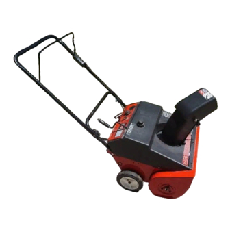
Yard Machines 140 Operator's Manual
Single stage
snow thrower
Hide thumbs
Also See for 140:
- Operator's manual (25 pages) ,
- Operation manual (25 pages) ,
- Operator's manual (10 pages)
Table of Contents
Advertisement
Operator's Manual
Single Stage
Snow Thrower
Model Series
140 through E173
IMPORTANT: Read safety rules and instructions carefully before operating equipment.
Warning:
This unit is equipped with an internal combustion engine and should not be used on or near any unimproved forest-
covered, brush-covered or grass-covered land unless the engine's exhaust system is equipped with a spark arrester meeting
applicable local or state laws (if any). If a spark arrester is used, it should be maintained in effective working order by the operator.
In the State of California the above is required by law (Section 4442 of the California Public Resources Code). Other states may have
similar laws. Federal laws apply on federal lands. A spark arrester for the muffler is available through your nearest engine authorized
service dealer or contact the service department, P.O. Box 368022 Cleveland, Ohio 44136-9722.
MTD PRODUCTS INC. P.O. BOX 368022 CLEVELAND, OHIO 44136-9722
PRINTED IN U.S.A.
. 770-10000B.fm
FORM NO
ECO No. 1223
(6/2000)
Advertisement
Table of Contents

Related Manuals for Yard Machines 140


Summary of Contents for Yard Machines 140
-
Page 1: Snow Thrower
Single Stage Snow Thrower Model Series 140 through E173 IMPORTANT: Read safety rules and instructions carefully before operating equipment. Warning: This unit is equipped with an internal combustion engine and should not be used on or near any unimproved forest- covered, brush-covered or grass-covered land unless the engine’s exhaust system is equipped with a spark arrester meeting... -
Page 2: Table Of Contents
TABLE OF CONTENTS Content Page Important Safe Operation Practices .................. 3 Assembling Your Snow Thrower ..................5 Know Your Snow Thrower....................7 Operating Your Snow Thrower ..................8 Making Adjustments......................9 Maintaining Your Snow Thrower ..................10 Off-Season Storage ......................10 Troubleshooting ........................ -
Page 3: Important Safe Operation Practices
SECTION 1: IMPORTANT SAFE OPERATION PRACTICES WARNING: This symbol points out important safety instructions which, if not followed, could endanger the personal safety and/or property of yourself and others. Read and follow all instructions in this manual before attempting to operate this machine. Failure to comply with these instructions may result in personal injury. When you see this symbol—heed its warning. - Page 4 Maintenance And Storage Do not operate machine while under the influence of alcohol or drugs. Never tamper with safety devices. Check their proper Muffler and engine become hot and can cause a burn. Do operation regularly. not touch. Disengage all clutch levers and stop engine. Wait until Exercise extreme caution when operating on or crossing the auger/impeller come to a complete stop.
-
Page 5: Assembling Your Snow Thrower
SECTION 2: ASSEMBLING YOUR SNOW THROWER Unpacking From Carton Before Assembly • Cut along corners of the carton and lay it down flat. WARNING: Disconnect the spark plug wire See Figure 1. Remove packing material. and ground it against the engine to prevent •... - Page 6 • Lift the control handle up, and hook the “Z” end of • Secure eyebolt with 5/16” saddle washer and hex the control cable into the bottom hole in the control nut. The cupped side of washer goes against the handle, from the outside to the inside .
-
Page 7: Know Your Snow Thrower
SECTION 3: KNOW YOUR SNOW THROWER Be familiar with all the controls and their proper operation. Know how to stop the machine and disengage them quickly. Auger Control Handle Upper Handle Auger Control Handle Extended Chute Crank Chute Crank Ignition Spark Primer Plug... -
Page 8: Operating Your Snow Thrower
SECTION 4: OPERATING YOUR SNOW THROWER Before Starting • After making sure no bystanders or obstacles are in front of the unit, engage the auger control handle. See Figure 11. As the snow thrower starts to move, WARNING: Read, understand, and follow maintain a firm hold on the handle, and guide the all instructions and warnings on the machine snow thrower along the path to be cleared. -
Page 9: Making Adjustments
SECTION 5: MAKING ADJUSTMENTS WARNING: belt tension, following instructions below, if the augers NEVER attempt to make any seem to hesitate while turning although engine adjustments while the engine is running, except maintains the same speed. where specified in the operator’s manual. •... -
Page 10: Maintaining Your Snow Thrower
SECTION 6: MAINTAINING YOUR SNOW THROWER Replacing Shave Plate WARNING: Before servicing, repairing, or inspecting, disengage all clutch levers and The shave plate is subject to wear. It should be stop engine. Wait until all moving parts have checked periodically. There are two wearing edges and come to a complete stop. -
Page 11: Troubleshooting
SECTION 8: TROUBLESHOOTING GUIDE Problem Cause Remedy Engine fails to start Fuel tank empty, or stale fuel Fill tank with clean fresh gasoline/oil mixture as specified in the engine manual. Blocked fuel line Clean fuel line Key not in ON position Insert key and turn to ON position Spark plug wire disconnected Connect wire to spark plug. -
Page 12: Parts List
SECTION 9: PARTS LIST FOR MODEL SERIES 140 THROUGH E173 46 37 31 32 23 12... - Page 13 Model Series 140 Through E173 Ref. No. Part No. Part Description Ref. No. Part No. Part Description 710-0167 Carriage Bolt 736-0176 Flat Washer 710-0276 Carriage Bolt 736-0159 Washer 710-0323 Pan Head Screw 736-0326 Flat Washer 710-0451 Carriage Bolt 736-0329 Lock Washer...
- Page 14 Models 140, 150, E150 and E151 Ref. No. Part No. Part Description 710-1270 Oval C-Sunk Screw 710-0487 Carriage Bolt 712-0324 Lock Nut 720-0284 Handle Knob 725-0157 Cable Tie 746-0883 Control Lever 747-0946 Control Handle Assembly 749-0705 Upper Handle 736-0451 Saddle Washer Models 142, E152, E172 and E173 Ref.
- Page 15 Model Series 140 Ref. No. Part No. Part Description 710-0157 Hex Screw 5/16-24 x 0.75” 710-0805 Hex Screw 5/16-18 x 1.5” 710-1652 Self-Tapping Screw 1/4-20 x .625” 726-0205 Hose Clamp 736-0119 Lock Washer 736-0242 Beleville Washer 750-0589 Spacer 750-0716 Spacer...
- Page 16 Models 150 through 172, E150 through E172 15** Ref. No. Part No. Part Description 629-0236 Extension Cord *Electric start models only 705-5139A Support Bracket: Gas Tank 710-0157 Hex Screw 5/16-24 x .75” 710-1003 Special Screw 710-1652 Self-Tapping Screw 710-3013 Hex Screw 1/4-20 x .50” 710-3025 Hex Screw 5/16-24 x .625 726-0152...
- Page 17 726-0100 Nut Push 735-0234 Grommet - Rubber † 731-0702 Shroud 747-0697 Eyebolt - Chute Crank † 731-1133B Plug 712-3010 Nut - Hex † 736-0119 Lock Washer 736-0451 Washer - Saddle † † Optional chute crank assembly on Model 140 only...
- Page 18 Model Series 150 and E150 Ref. No. Part No. Part Description Ref. No. Part No. Part Description 684-0126 Chute Crank Assembly 726-0100 Push Cap 684-0160 Dash Assembly 731-1089A Choke Cover 710-1003 Special Screw 731-1133B 710-1090 Hex Flange Screw 731-1988 Shroud: 21” Yellow 710-1268 Special Screw 731-1087...
- Page 19 Models E160 through E172 Ref. No. Part No. Part Description Ref. No. Part No. Part Description 725-1347 Ignition Switch Cap 684-0126 Chute Crank Assembly 725-1425 Switch: Recoil Start Key 684-0160 Dash Assembly 726-0100 Push Cap 710-1003 Special Screw 731-1089A Choke Cover 710-1090 Hex Flange Screw 5/16-18 x 1.25”...
- Page 20 MANUFACTURER’S LIMITED WARRANTY FOR: b. Routine maintenance items such as lubricants, filters, The limited warranty set forth below is given by MTD blade sharpening and tune-ups, or adjustments such PRODUCTS INC (“MTD”) with respect to new merchandise as brake adjustments, clutch adjustments or deck purchased and used in the United States, its possessions adjustments;...
Need help?
Do you have a question about the 140 and is the answer not in the manual?
Questions and answers