Table of Contents
Advertisement
Available languages
Available languages
OPERATOR'S MANUAL
MANUEL D'UTILISATION
MANUAL DEL OPERADOR
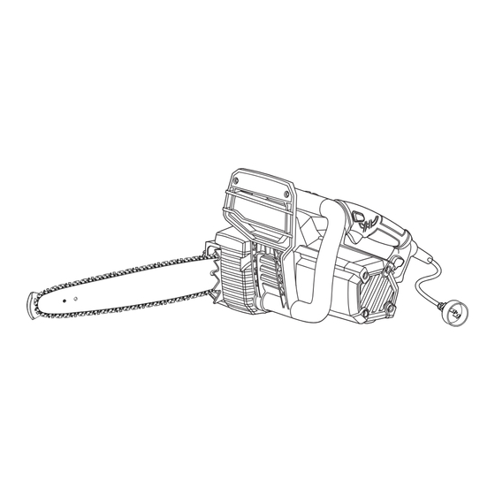
16 in. ELECTRIC CHAIN SAW
SCIE À CHAÎNE ÉLECTRIQUE
DE 406 mm (16 po)
MOTOSIERRA ELÉCTRICA
DE 406 mm (16 pulg.)
RY43154
Your chain saw has been engineered and manufactured to our high standard for dependability, ease of operation, and
operator safety. When properly cared for, it will give you years of rugged, trouble-free performance.
WARNING:
this product.
Thank you for your purchase.
SAVE THIS MANUAL FOR FUTURE REFERENCE
Cette scie à chaîne a été conçue et fabriquée conformément
aux strictes normes de fiabilité, simplicité d'emploi et sécurité
d'utilisation. Correctement entretenue, elle vous donnera des années
de fonctionnement robuste et sans problème.
AVERTISSEMENT :
blessures, l'utilisateur doit lire et veiller à bien comprendre le
manuel d'utilisation avant d'employer ce produit.
Merci de votre achat.
CONSERVER CE MANUEL POUR
FUTURE RÉFÉRENCE
To reduce the risk of injury, the user must read and understand the operator's manual before using
Pour réduire les risques de
Su motosierra inalámbrica ha sido diseñada y fabrica-
da de conformidad con nuestras estrictas normas para
brindar fiabilidad, facilidad de uso y seguridad para el opera-
dor. Con el debido cuidado, le brindará muchos años de sólido
y eficiente funcionamiento.
ADVERTENCIA:
el usuario debe leer y comprender el manual del operador antes
de usar este producto.
Le agradecemos su compra.
GUARDE ESTE MANUAL PARA
FUTURAS CONSULTAS
Para reducir el riesgo de lesiones,
Advertisement
Table of Contents

Subscribe to Our Youtube Channel
Related Manuals for Ryobi RY43154


Summary of Contents for Ryobi RY43154
- Page 1 MOTOSIERRA ELÉCTRICA DE 406 mm (16 pulg.) RY43154 Your chain saw has been engineered and manufactured to our high standard for dependability, ease of operation, and operator safety. When properly cared for, it will give you years of rugged, trouble-free performance.
-
Page 2: Table Of Contents
TABLE OF CONTENTS TABLE DES MATIÈRES / ÍNDICE DE CONTENIDO Introduction ............................2 Introduction / Introducción General Power Tool Safety Warnings .................... 3-4 Règles de sécurité générales relatives aux outils électriques / Advertencias de seguridad para herramientas eléctrica Chain Saw Safety Warnings ......................5-9 Avertissements de sécurité... -
Page 3: General Power Tool Safety Warnings
GENERAL POWER TOOL SAFETY WARNINGS If operating a power tool in a damp location WARNING is unavoidable, use a ground fault circuit interrupter (GFCI) protected supply with a Read all safety warnings and all instructions. tripping current of 30 mA or less. Use of a Failure to follow the warnings and instructions GFCI reduces the risk of electric shock. -
Page 4: Avertissements De Sécurité Relatifs Au Scie À Chaîne / Advertencias De Seguridad De La Motosierra
GENERAL POWER TOOL SAFETY WARNINGS Do not use the power tool if the switch does Keep cutting tools sharp and clean. Prop- not turn it on and off. Any power tool that can- erly maintained cutting tools with sharp cutting not be controlled with the switch is dangerous edges are less likely to bind and are easier to and must be repaired. -
Page 5: Chain Saw Safety Warnings
CHAIN SAW SAFETY WARNINGS Proper handling of the chain saw will reduce the Keep all parts of the body away from the likelihood of accidental contact with the moving saw chain when the chain saw is operating. saw chain. Before you start the chain saw, make sure the saw chain is not contacting anything. - Page 6 CHAIN SAW SAFETY WARNINGS cord will cause a drop in line voltage resulting Do not overreach and do not cut above chest in loss of power and overheating. height. This helps prevent unintended tip con- tact and enables better control of the chain saw Inspect extension cords periodically and, if dam- in unexpected situations.
- Page 7 Never let anyone use your chain saw who has in the operation and maintenance sections, not received adequate instructions in its proper should be performed by your nearest RYOBI use. This applies to rentals as well as privately service dealer.
- Page 8 CHAIN SAW SAFETY WARNINGS KICKBACK ROTATIONAL See Figures 1 - 2. KICKBACK WARNING: Kickback may occur when the moving chain contacts an object at the upper portion of the tip of the guide bar or when the wood closes in and pinches the saw chain in the cut.
-
Page 9: Chain Saw Safety Warnings
CHAIN SAW SAFETY WARNINGS UNDERSTANDING YOUR CHAIN SAW SAFETY DEVICES See Figure 4. SAFE-T-TIP ANTI-KICKBACK NOSE GUARD The SAFE-T-TIP prevents rotational kickback from happening, because it covers the tip of the bar where kickback is generated. Never attempt any PULL kind of cutting where the SAFE-T-TIP would have to be removed from the bar tip. -
Page 10: Symbols
SYMBOLS The following signal words and meanings are intended to explain the levels of risk associated with this product. SYMBOL SIGNAL MEANING Indicates a hazardous situation, which, if not avoided, will result DANGER: in death or serious injury. Indicates a hazardous situation, which, if not avoided, could WARNING: result in death or serious injury. -
Page 11: Symbols
SYMBOLS Some of the following symbols may be used on this product. Please study them and learn their meaning. Proper interpretation of these symbols will allow you to operate the product better and safer. SYMBOL NAME DESIGNATION/EXPLANATION Wear non-slip, heavy-duty protective gloves when Wear Gloves handling the chain saw. -
Page 12: Electrical
ELECTRICAL DOUBLE INSULATION Before using any extension cord, inspect it for loose or exposed wires and cut or worn insulation. Double insulation is a concept in safety in electric A proper extension cord is available at an autho- power tools, which eliminates the need for the usual rized service center. -
Page 13: Glossary Of Terms
GLOSSARY OF TERMS Bucking Low-Kickback Chain The process of cross cutting a felled tree or log into A chain that complies with the kickback performance lengths. requirements of ANSI B175.1 when tested on a repre- sentative sample of chain saws. Chain Brake Normal Cutting Position A device used to stop the saw chain. -
Page 14: Features
FEATURES PRODUCT SPECIFICATIONS Bar length ............................16 in. Chain pitch ..........................375 in. Chain gauge ..........................050 in. Chain type ......................Low Profile Skip Tooth Drive sprocket ..........................6-tooth Input ...................nominal 120V/60Hz AC only, 12 Amps Chain oil tank capacity .........................6.8 oz. FRONT HANDLE SWITCH CHAIN BRAKE/FRONT LOCK-OUT... -
Page 15: Features
FEATURES KNOW YOUR CHAIN SAW QUICK VIEW OIL INDICATOR See Figure 6. Semi-transparent oil reservoir that allows user to The safe use of this product requires an under- see when to add oil. standing of the information on the tool and in this SAFE-T-TIP ANTI-KICKBACK NOSE ®... -
Page 16: Assembly
ASSEMBLY UNPACKING PACKING LIST This product has been shipped completely Chain Saw assembled. Scabbard Carefully remove the product and any acces- Operator’s Manual sories from the box. Make sure that all items listed in the packing list are included. WARNING: If any parts are damaged or missing do not WARNING:... -
Page 17: Operation
OPERATION ADDING BAR AND CHAIN LUBRICANT WARNING: See Figure 7. NOTE: Chain saw comes from the factory with Do not use any attachments or accessories no bar and chain lubricant added. Level should not recommended by the manufacturer of this also be checked after every 20 minutes of use and product. - Page 18 OPERATION OPERATING THE MANUAL CHAIN BRAKE See Figures 8 - 9. Check the operating condition of the chain brake BRAKE prior to each use. POSITION Using the back of your left hand, engage the chain brake by pushing the chain brake/front hand guard toward the bar while the chain is rotating rapidly.
- Page 19 OPERATION STARTING AND STOPPING THE CHAIN SWITCH LOCK-OUT See Figure 11. SWITCH TRIGGER WARNING: Keep body to the left of the chain line. Never straddle the saw or chain, or lean over past the chain line. Starting the chain saw: Make sure chain tension is at desired setting.
- Page 20 OPERATION PREPARING FOR CUTTING PROPER GRIP ON HANDLES See Figure 14. See General Power Tool Safety Warnings for appro- priate safety equipment. Wear non-slip gloves for maximum grip and PROPER HAND protection. GRIP POSITION Hold the saw firmly with both hands. Always keep your left hand on the front handle and your right hand on the rear handle so that your body is to the left of the chain line.
- Page 21 OPERATION Balance your weight with both feet on solid CHAIN STRAIGHT ARM ground. LINE THUMB ON Keep left arm with elbow locked in a “straight UNDERSIDE OF arm” position to withstand any kickback force. HANDLE BAR Keep your body to the left of the chain line. Keep your thumb on underside of handlebar.
-
Page 22: Felling Trees
OPERATION FELLING TREES See Figures 17 - 20. HAZARDOUS CONDITIONS WARNING: Do not fell trees during periods of high wind or heavy precipitation. Wait until the hazardous weather has ended. 45° WARNING: Closely check for broken or dead branches, PLANNED 45°... - Page 23 OPERATION Remove dirt, stones, loose bark, nails, staples, and wire from the tree where felling cuts are to be made. HINGE Notched Undercut. Cut a notch about 1/3 the 2 in. OR 1/10 DIAMETER diameter of the tree, perpendicular to the direc- tion of fall.
- Page 24 OPERATION REMOVING BUTTRESS ROOTS See Figure 21. A buttress root is a large root extending from the trunk of the tree above the ground. Remove large VERTICAL buttress roots prior to felling. Make the horizontal cut into the buttress first, followed by the vertical LOOSE cut.
- Page 25 OPERATION BUCKING LOGS UNDER STRESS LOG SUPPORTED AT ONE END See Figure 24. LOAD FINISHING CUT Make the first bucking cut 1/3 of the way through the log and finish with a 2/3 cut on the opposite side. As you cut the log, it will tend to bend. The saw can become pinched or hung in the log if you make the first cut deeper than 1/3 of the diameter of the log.
- Page 26 OPERATION LIMBING See Figure 27. Limbing is removing branches from a fallen tree. Work slowly, keeping both hands on the chain saw with a firm grip. Always make sure your footing is secure and your weight is distributed evenly on both feet. ...
-
Page 27: Maintenance
OPERATION CUTTING SPRINGPOLES See Figure 29. A springpole is any log, branch, rooted stump, or sapling which is bent under tension by other wood so that it springs back if the wood holding it is cut or removed. On a fallen tree, a rooted stump has a high potential of springing back to the upright SPRINGPOLE position during the bucking cut to separate the log... - Page 28 MAINTENANCE LUBRICATION All of the bearings in this product are lubricated with a sufficient amount of high grade lubricant for the life of the unit under normal operating condi- tions. Therefore, no further lubrication is required. REPLACING THE BAR AND CHAIN See Figures 30 - 38.
- Page 29 MAINTENANCE Rotate the chain tension assembly clockwise a in the direction of chain rotation. If they face few turns to take up enough slack in the chain backwards, turn the loop over. so it stays in position. Place the chain drive links into the bar groove as Replace the chain cover.
- Page 30 MAINTENANCE Lift the tip of the guide bar up to check for sag. Release the tip of the guide bar and turn the chain tensioning knob 1/2 turn clockwise. Repeat this process until sag does not exist. Hold the tip of the guide bar up and tighten the chain cover lock knob.
-
Page 31: Chain Maintenance
MAINTENANCE CHAIN MAINTENANCE RAKER (DEPTH GAUGE) CLEARANCE See Figures 41 - 42. WARNING: Before performing any maintenance, make sure .025 in. the tool is unplugged from the power supply. Failure to comply could result in accidental Fig. 41 starting and possible serious personal injury. INSPECT DRIVE SPROCKET Use only a low-kickback chain on this saw. - Page 32 MAINTENANCE Tension the chain prior to sharpening. Refer to Adjusting the Chain Tension. Use a 5/32 in. diameter round file and holder. Do all of your filing at the midpoint of the bar. Keep the file level with the top plate of the tooth. Do not let the file dip or rock.
- Page 33 MAINTENANCE SIDE PLATE ANGLE SIDE PLATE FILING ANGLE See Figure 48. 80° CORRECT 80° – Produced automatically if you use the correct diameter file in the file holder. HOOK – “Grabs” and dulls quickly; increases CORRECT the potential of KICKBACK. Results from using HOOK BACKWARD SLOPE a file with a diameter too small or a file held too...
- Page 34 MAINTENANCE MAINTAINING THE GUIDE BAR See Figure 52. WARNING: Before performing any maintenance, make sure LUBRICATING HOLE the tool is unplugged from the power supply. Failure to comply could result in accidental starting and possible serious personal injury. Fig. 52 Every week of use, reverse the guide bar on the MOUNTING saw to distribute the wear for maximum bar life.
- Page 35 MAINTENANCE MAINTAINING THE SAFE-T-TIP NOSE TRANSPORTING AND STORING GUARD See Figure 55. Do not store or transport the chain saw when See Figures 53 - 54. it is running. The chain saw should always be WARNING: idle before storing or transporting. Disconnect chain saw from power supply.
-
Page 36: Bar And Chain Combinations
CALL US FIRST For any questions about operating or maintaining your product, call the Ryobi Help Line! Your product has been fully tested prior to shipment to ensure your complete satisfaction. Page 36 — English... -
Page 37: Warranty
Straps, Guide Bars, Saw Chains purchase. Techtronic Industries North America, Inc., reserves the Three years if the product is used for personal, family right to change or improve the design of any RYOBI brand ® or household use;... - Page 38 RÈGLES DE SÉCURITÉ RELATIVES AUX OUTILS ÉLECTRIQUES le cordon à l’écart de la chaleur, de l’huile, AVERTISSEMENT des objets tranchants et des pièces en mouvement. Un cordon endommagé ou Lire tous les avertissements et toutes emmêlé accroît le risque de choc électrique. les instructions.
- Page 39 RÈGLES DE SÉCURITÉ RELATIVES AUX OUTILS ÉLECTRIQUES Si les outils sont équipés de dispositifs ou bloquée, qu’aucune pièce n’est brisée et de dépoussiérage, s’assurer qu’ils sont s’assurer qu’aucun autre problème ne risque connectés et correctement utilisés. L’usage d’affecter le bon fonctionnement de l’outil. de ces dispositifs de dépoussiérage peut En cas de dommages faire réparer l’outil avant réduire les dangers présentés par la poussière.
- Page 40 AVERTISSEMENTS DE SÉCURITÉ RELATIFS AU SCIE À CHAÎNE et les pieds est recommandé. Des vêtements couper du plastique, de la maçonnerie ou des de protection adéquats réduiront le risque de matériaux de construction non dérivés du blessures causées par les objets projetés ou le bois.
- Page 41 AVERTISSEMENTS DE SÉCURITÉ RELATIFS AU SCIE À CHAÎNE Suivre les instructions d’affûtage et faire réparer par un électricien diplômé. Toujours d’entretien fournies par le fabricant de la être conscient de l’emplacement du cordon Le scie à chaîne. La diminution du limiteur de respect de cette règle réduira les risques de profondeur augmente le risque de rebond.
- Page 42 Tous les entretiens et dépannages, autres que ceux décrits dans le manuel d’utilisation doivent Garder toutes les parties du corps à l’écart de être confiés au centre de réparation RYOBI le la scie à chaîne lorsque le moteur tourne. plus proche.
- Page 43 AVERTISSEMENTS DE SÉCURITÉ RELATIFS AU SCIE À CHAÎNE REBOND REBOND Voir les figures 1 et 2. ROTATIF AVERTISSEMENT Le rebond se produit lorsque la chaîne en rotation heurte un objet dans la partie supérieure de l’extrémité du guide ou lorsque l’entaille du bois se referme et pince la chaîne dans le bois.
- Page 44 AVERTISSEMENTS DE SÉCURITÉ RELATIFS AU SCIE À CHAÎNE effectuée avec le bas du guide et la POUSSÉE lorsque la coupe est effectuée avec le haut du guide. Voir la figure 3. COMPRÉHENSION DES DISPOSITIFS DE SÉCURITÉ DE LA SCIE À CHAÎNE Voir la figure 4.
- Page 45 SYMBOLES Les termes de mise en garde suivants et leur signification ont pour but d’expliquer le degré de risques associé à l’utilisation de ce produit. SYMBOLE SIGNAL SIGNIFICATION Indique une situation dangereuse qui, si elle n’est pas DANGER : évitée, aura pour conséquences des blessures graves ou mortelles.
- Page 46 SYMBOLES Certains des symboles ci-dessous peuvent être utilisés sur ce produit. Veiller à les étudier et à apprendre leur signification. Une interprétation correcte de ces symboles permettra d’utiliser ce produit plus efficacement et de réduire les risques. SYMBOLE DÉSIGNATION / EXPLICATION Rebond DANGER ! ATTENTION AUX REBONDS.
- Page 47 CARACTÉRISTIQUES ÉLECTRIQUES ISOLATION DOUBLE Avant d’utiliser un cordon prolongateur, vérifier que ses fils ne sont ni détachés ni exposés et que son isolation L’isolation double est un concept de sécurité des outils n’est ni coupée, ni usée. électriques qui élimine le besoin de cordon d’alimentation Il est possible de se procurer une rallonge électrique à...
- Page 48 GLOSSAIRE Tronçonnage Chaîne à rebond réduit Coupe transversale d’un arbre abattu ou d’une bille de Chaîne conforme aux normes antirebond ANSI B175.1 bois pour le débiter en tronçons. lorsqu’elle est testée sur des échantillons représentatifs de scies à chaîne. Frein de chaîne Position de coupe normale Dispositif permettant d’arrêter la scie à...
- Page 49 CARACTÉRISTIQUES SPÉCIFICATIONS Longueur du guide ........................406 mm (16 po) Pas de la chaîne ....................... 9,5 mm (0,375 po) Épaisseur de la chaîne ....................1,27 mm (0,050 po) Type de chaîne ....................Dents bas profil à saut intégral Pignon d’entraînement ........................6-dents Alimentation.............caractéristique nominal CA de 120V/60 Hz seulement, 12 A Volume du réservoir de lubrifiant de chaîne ................
- Page 50 CARACTÉRISTIQUES POUR SE FAMILIARISER AVEC LA CHAÎNE À REBOND RÉDUIT SCIE À CHAÎNE La chaîne à rebond réduit aide à limiter la force Voir la figure 6. de réaction du rebond en empêchant les dents de mordre trop profondément dans la zone de rebond. L’utilisation sûre de ce produit exige une comprehension des renseignements figurant sur REGARD DE NIVEAU D’HUILE...
- Page 51 ASSEMBLAGE DÉBALLAGE AVERTISSEMENT : Ce produit a été expédié complètement assemblé. Si des pièces manquent ou sont endommagées, Avec précaution, sortir le produit et les accessoires ne pas utiliser ce produit avant qu’elles aient été de la boîte. S’assurer que toutes les pièces remplacées.
- Page 52 UTILISATION APPOINT DE LUBRIFIANT POUR AVERTISSEMENT : GUIDE ET CHAÎNE Ne pas utiliser d’outils ou accessoires non Voir la figure 7. recommandés pour ce produit. L’utilisation de NOTE : La scie à chaîne sort d’usine sans guide et pièces et accessoires non recommandés peut sans lubrifiant de chaîne ajoutée.
- Page 53 UTILISATION UTILISATION DU FREIN DE CHAÎNE MANUEL Voir les figures 8 et 9. FREIN Le fonctionnement du frein de chaîne doit être ENGAGÉ vérifié avant chaque utilisation. Avec le dos de la main gauche, engager le frein de chaîne en poussant le frein de chaîne/ protection de poignée avant en direction du guide pendant que la chaîne tourne à...
- Page 54 UTILISATION DÉMARRAGE ET ARRÊT DE LA SCIE À VERROUILLAGE DU CHAÎNE COMMUTATEUR Voir la figure 11. GÂCHETTE AVERTISSEMENT : Garder le corps à droite de la ligne de chaîne. Ne jamais chevaucher la scie ou la chaîne ou se pencher au-delà de la ligne de chaîne. Démarrage de la scie à...
- Page 55 UTILISATION PRÉPARATION POUR LA COUPE TENUE CORRECTE DES POIGNÉES Voir la figure 14. Voir Règles de sécurité générales relatives aux outils électriques pour des informations au sujet de TENUE CORRECTE l’équipement de sécurité approprié. DES POIGNÉES Porter des gants antidérapants pour assurer une prise et une protection maximum.
- Page 56 UTILISATION Se tenir bien campé et en équilibre sur les deux BRAS LIGNE DE pieds, sur un sol ferme. CHAÎNE TENDU POUCE Garder le bras gauche tendu afin de pouvoir AU-DESSOUS résister à la force d’un éventuel rebond. DE LA POIGNÉE Garder le corps à...
- Page 57 UTILISATION ABATTAGE D’ARBRES Voir les figures 17 à 20. SITUATIONS DANGEREUSES AVERTISSEMENT : Ne pas effectuer d’abattage par grand vent ou en cas de fortes précipitations. Attendre que le temps se calme. 45° AVERTISSEMENT : LIGNE DE Surveiller attentivement les branches brisées ou CHUTE 45°...
- Page 58 UTILISATION grosses branches. Tous ces facteurs influencent la direction dans laquelle l’arbre tombera. Ne pas faire levier pour abattre un arbre dans une CHARNIÈRE DE 51 mm (2 po) direction autre que la ligne de chute naturelle. OU 1/10 ÈME DU DIAMÈTRE ...
- Page 59 UTILISATION ÉLIMINATION DES RACINES ÉCHASSES Voir la figure 21. Une racine échasse est une grosse racine qui s’étend COUPE à partir du tronc au-dessus du sol. Retirer les grosses VERTICALE racines échasses avant d’abattre l’arbre. Pratiquer SECTION d’abord l’entaille horizontale dans la racine échasse, COUPÉE puis l’entaille verticale.
- Page 60 UTILISATION DÉBITAGE DE BILLES SOUS BILLE SOUTENUE À UNE EXTRÉMITÉ CONTRAINTE COUPE DE Voir la figure 24. CHARGE FINITION Pratiquer la première entaille à 1/3 du diamètre de la pièce et finir la coupe des 2/3 restant depuis le côté opposé. À mesure qu’elle est coupée, la bille a tendance à...
- Page 61 UTILISATION ÉBRANCHAGE Voir la figure 27. L’ébranchage revient à couper les branches d’un arbre abattu. Travailler lentement et tenir la scie fermement à deux mains. Toujours veiller à se tenir bien campé et en équilibre sur les deux pieds. COUPER LES BRANCHES UNE À...
- Page 62 UTILISATION AVERTISSEMENT : Les fouets sont dangereux et peuvent heurter l’opérateur, lui faisant perdre le contrôle de la scie. Ceci peut entraîner des blessures graves ou mortelles. FOUET Fig. 29 ENTRETIEN ENTRETIEN GÉNÉRAL AVERTISSEMENT : Éviter d’utiliser des solvants pour le nettoyage Avant d’effectuer tout entretien, s’assurer des pièces en plastique.
- Page 63 ENTRETIEN REMPLACEMENT DU GUIDE ET DE LA CHAÎNE Voir les figures 30 à 38. AVERTISSEMENT : Ne jamais mettre le moteur en marche sans que le guide, la chaîne, le capot moteur et le couvercle de chaîne de bouton de verrouillage soient en place.
- Page 64 ENTRETIEN chaîne. Si elles sont orientées dans le sens Ajuster le guide au ras de la surface de montage, contraire, retourner la boucle. de manière à ce que ses supports s’engagent dans la fente longue du guide. Engager les maillons d’entraînement de la chaîne dans la rainure du guide conformément Tourner l’assemblage du tendeur de chaîne vers à...
- Page 65 ENTRETIEN Tournez droit le la couvercle de chaîne de bouton de verrouillage serrer. Le mouvement du guide est nécessaire pour le réglage de la tension. Éliminer complètement le mou de la chaîne en tournant l’anneau de réglage de tension de la chaîne vers la droite jusqu’à...
- Page 66 ENTRETIEN La chaîne doit être retendue lorsque les méplats JEU DU LIMITEUR DE PROFONDEUR des maillons d’entraînement sortent de la rainure du guide. NOTE : Pendant l’utilisation normale de la scie, la 0,6 mm température de la chaîne augmente. Les maillons (0,025 po) d’entraînement d’une chaîne chaude correctement tendue pendent à...
- Page 67 ENTRETIEN AFFÛTAGE DES DENTS COUPE DU COIN Voir les figures 43 à 46. PLAQUETTE PLAQUE Veiller à limer toutes les dents aux angles spécifiés SUPÉRIEURE LATÉRALE et à la même longueur, car une coupe rapide ne LIMITEUR DE TROU DE peut être obtenue qu’avec des dents uniformes.
- Page 68 ENTRETIEN ANGLE D’AFFÛTAGE DE LA PLAQUE SUPÉRIEURE AVERTISSEMENT : 30° L’utilisation d’une chaîne endommagée pourrait causer des blessures graves. AVIS : CORRECT MOINS DE 30° PLUS DE 30° Une chaîne émoussée ou incorrectement affûtée peut causer un régime excessif du moteur pendant la coupe et l’endommager gravement.
- Page 69 ENTRETIEN endommager les maillons d’entraînement COUPLEUR DE LIMITEUR DE PROFONDEUR adjacents avec le bord de la lime. Les limiteurs de profondeur doivent être ajustés avec la lime plate, dans le sens dans lequel les dents adjacentes ont été affûtées avec la lime ronde.
- Page 70 ENTRETIEN ENTRETIEN DE LA GARDE SAFE-T-TIP SERRER DE 3/4 Voir les figures 53 et 54. DE TOUR AVERTISSEMENT : Bien que le dispositif antirebond SAFE-T-TIP ait été installé en usine, vérifier le serrage de sa vis de montage avant chaque utilisation pour éviter tout risque de blessures graves.
- Page 71 NOUS APPELER D’ABORD Pour toute question concernant l’utilisation ou l’entretien utiliser ce produit, appeler le service d’assistance téléphonique Ryobi ! Le taille-bordures à été entièrement testé avant expédition pour assurer la complète satisfaction de l’utilisateur.
- Page 72 Le produit, y compris toutes les pièces défectueuses devront AMERICA, INC., DANS LE CADRE DE CETTE GARANTIE être retournés à un centre de réparations Ryobi agréé, avant SE LIMITENT EXCLUSIVEMENT À LA RÉPARATION OU expiration de la période de garantie. Les frais d’expédition AU REMPLACEMENT DES PIÈCES DÉFECTUEUSES...
- Page 73 ADVERTENCIAS DE SEGURIDAD PARA HERRAMIENTAS ELÉCTRICAS No maltrate el cordón eléctrico. Nunca utilice ADVERTENCIA el cordón para trasladar, desconectar o tirar de la herramienta eléctrica. Mantenga el cordón Lea todas las advertencias de seguridad lejos del calor, aceite, bordes afilados y piezas y las instrucciones.
- Page 74 ADVERTENCIAS DE SEGURIDAD PARA HERRAMIENTAS ELÉCTRICAS No estire el cuerpo para alcanzar mayor y no permita que las utilicen personas no distancia. Mantenga una postura firme y buen familiarizadas con las mismas o con estas equilibrio en todo momento. De esta manera se instrucciones.
- Page 75 ADVERTENCIAS DE SEGURIDAD DE LA MOTOSIERRA Siempre sostenga la motosierra con la mano son resbaladizos y pueden hacerle perder el derecha en el mango trasero y la mano control. izquierda en el mango delantero. Sostener la Corte únicamente madera. No use la motosierra motosierra con las manos invertidas aumenta para usos distintos de los previstos.
- Page 76 ADVERTENCIAS DE SEGURIDAD DE LA MOTOSIERRA Use únicamente barras y cadenas de repuesto Inspeccione periódicamente los cordones de indicadas por el fabricante. El uso de barras y extensión, y si están dañados, permita que cadenas de repuesto incorrectas podría hacer los repare un electricista calificado.
- Page 77 Esto se y mantenimiento deben ser efectuados en el aplica tanto a las sierras alquiladas como a las establecimiento de servicio de productos RYOBI propias. de su preferencia. Antes de arrancar la unidad, asegúrese de que la Siempre mantenga una postura correcta.
- Page 78 ADVERTENCIAS DE SEGURIDAD DE LA MOTOSIERRA CONTRAGOLPE Vea las figuras 1 y 2. CONTRAGOLPE ROTATORIO ADVERTENCIA: El contragolpe ocurre cuando la cadena en movimiento hace contacto con un objeto en la parte superior de la punta de la barra, o cuando la madera se cierra y pellizca la cadena de la sierra en el punto de corte.
- Page 79 ADVERTENCIAS DE SEGURIDAD DE LA MOTOSIERRA EXPLICACIÓN DE LOS DISPOSITIVOS DE SEGURIDAD DE LA MOTOSIERRA Vea la figura 4. SAFETTIP DE LA PUNTA La protección SAFETTIP evita el contragolpe rotatorio ya que cubre la punta de la barra, donde se genera el contragolpe. Nunca intente ninguna tarea de corte para la cual tuviera que desmontar TIRÓN la protección SAFETTIP de la punta de la barra.
- Page 80 SÍMBOLOS Las siguientes palabras de señalización y sus significados tienen el objeto de explicar los niveles de riesgo relacionados con este producto. SÍMBOLO SEÑAL SIGNIFICADO Indica una situación peligrosa, la cual, si no se evita, causará PELIGRO: la muerte o lesiones serias. Indica una situación peligrosa, la cual, si no se evita, podría ADVERTENCIA: causar la muerte o lesiones serias.
- Page 81 SÍMBOLOS Es posible que se empleen en este producto algunos de los siguientes símbolos. Le suplicamos estudiarlos y aprender su significado. Una correcta interpretación de estos símbolos le permitirá utilizar mejor y de manera más segura la producto. SÍMBOLO NOMBRE DENOMINACIÓN / EXPLICACIÓN Evite el contacto del material con la punta de la barra.
- Page 82 ASPECTOS ELÉCTRICOS DOBLE AISLAMIENTO Hay un cordón de extensión adecuado disponible en un centro de servicio autorizado. El doble aislamiento es una característica de seguridad de Se puede hacer un nudo para atar el cordón de extensión las herramientas eléctricas, la cual elimina la necesidad y el cordón eléctrico para impedir que se desconecten de usar el típico cordón eléctrico de tres conductores con durante el uso.
- Page 83 GLOSARIO DE TÉRMINOS Tronzado al probarse en una muestra representativa de las sierras de cadena. Es el proceso de cortar transversalmente un árbol o tronco talado en tramos. Posición normal de corte Freno de la cadena Son aquellas posiciones adoptadas para efectuar los cortes de tronzado y de tala de árboles.
- Page 84 CARACTERÍSTICAS ESPECIFICACIONES DEL PRODUCTO Longitud de la barra ........................406 mm (16 pulg.) Paso de la cadena ........................ 9,5 mm (0,375 pulg.) Calibre de la cadena......................1,27 mm (0,050 pulg.) Tipo de cadena ................. Dientes de bajo perfil de garganta ancha grande Rueda dentada de impulsión ......................
- Page 85 CARACTERÍSTICAS FAMILIARÍCESE CON LA INDICADOR DE NIVEL DE ACEITE MOTOSIERRA Es un tanque semitransparente de aceite que permite ver cuándo reabastecerlo de aceite. Vea la figura 6. Para usar este producto con la debida seguridad PROTECCIÓN ANTICONTRAGOLPE se debe comprender la información indicada en SAFETTIP DE LA PUNTA ®...
- Page 86 ARMADO DESEMPAQUETADO LISTA DE EMPAQUETADO Embarcamos este producto completamente armado. Motosierra Extraiga cuidadosamente de la caja la producto y Funda los accesorios. Asegúrese de que estén presentes Manual del operador todos los artículos enumerados en la lista de empaque. ADVERTENCIA: Si falta o está...
- Page 87 FUNCIONAMIENTO ABASTECIMIENTO DE LUBRICANTE ADVERTENCIA: PARA LA BARRA Y LA CADENA No utilice ningún aditamento o accesorio no Vea la figura 7. recomendado por el fabricante de este producto. NOTA: La cadena viene de la fábrica con la barra y El empleo de aditamentos o accesorios no la cadena sin lubricante.
- Page 88 FUNCIONAMIENTO FUNCIONAMIENTO DEL FRENO DE LA CADENA MANUAL Vea las figuras 8 y 9. POSICIÓN Verifique las condiciones de funcionamiento del freno DE FRENO de la cadena cada vez antes de usar la unidad. Con el dorso de la mano izquierda accione el freno de la cadena;...
- Page 89 FUNCIONAMIENTO ENCENDIDO Y APAGADO DE LA SEGURO DE APAGADO MOTOSIERRA DEL INTERRUPTOR Vea la figura 11. GATILLO DEL INTERRUPTOR ADVERTENCIA: Mantenga el cuerpo a la izquierda del plano de la cadena. Nunca se coloque a horcajadas por encima de la sierra o de la cadena, ni incline el cuerpo a través del plano de la cadena.
- Page 90 FUNCIONAMIENTO PREPARACIÓN PARA EL CORTE SUJECIÓN CORRECTA DE LOS MANGOS Vea la figura 14. POSICIÓN CORRECTA Consulte el apartado Advertencias de seguridad para DE LAS MANOS herramientas eléctrica, donde encontrará información EN LOS MANGOS sobre el equipo de seguridad adecuado. Póngase guantes antideslizantes para lograr una capacidad de sujeción y protección máximas.
- Page 91 FUNCIONAMIENTO Su peso debe quedar distribuido de forma EL BRAZO PLANO DE equilibrada con ambos pies en suelo firme. EL PULGAR BAJO RECTO LA CADENA LA BARRA DEL Mantenga el brazo izquierdo con el codo rígido MANGO en posición de “brazo recto” para poder tolerar la fuerza de cualquier contragolpe.
- Page 92 FUNCIONAMIENTO TALA DE ÁRBOLES Vea las figuras 17 a 20. CONDICIONES PELIGROSAS ADVERTENCIA: No tale árboles durante períodos de viento o lluvia intensos. Espere hasta que cese el tiempo peligroso. 45° ADVERTENCIA: LÍNEA 45° Controle con cuidado que no haya ramas rotas o PLANEADA muertas que puedan caer mientras tala, y no tale DE CAÍDA...
- Page 93 FUNCIONAMIENTO las ramas más grandes del mismo. Estos aspectos influyen en la dirección de caída del árbol. No trate de talar ningún árbol a lo largo de una línea BISAGRA 51 mm (2 pulg.) diferente de su línea natural de caída. O 1/10 DEL DIÁM.
- Page 94 FUNCIONAMIENTO ELIMINACIÓN DE RAÍCES ZANCAS Vea la figura 21. Una raíz zanca es una raíz larga que se extiende desde el tronco del árbol, por encima de la tierra. Antes CORTE de talar el árbol, elimine las raíces zancas grandes. VERTICAL Primero efectúe el corte horizontal en la raíz zanca, seguido del corte vertical.
- Page 95 FUNCIONAMIENTO TRONZADO DE TRONCOS BAJO TRONCO APOYADO POR UN EXTREMO TENSIÓN CARGA CORTE FINAL Vea la figura 24. Efectúe el primer corte de tronzado a 1/3 del espesor del tronco y termine con un corte de 2/3 por el lado opuesto. A medida que corta el tronco, éste tenderá...
- Page 96 FUNCIONAMIENTO DESRAMADO Vea la figura 27. El desramado es la eliminación de las ramas de un árbol cortado. Trabaje lentamente, manteniendo ambas manos en la motosierra, sujetándola firmemente. Siempre asegúrese de mantener una postura firme y de distribuir su peso de forma equilibrada CORTE UNA RAMA A LA VEZ Y DEJE RAMAS DE SOPORTE BAJO EL ÁRBOL HASTA QUE ESTÉ...
- Page 97 FUNCIONAMIENTO si se corta o se elimina el elemento que lo detiene. Con la cepa enraizada de un árbol caído hay un gran peligro de que la misma vuelva súbitamente a la posición vertical durante el corte de tronzado para separar el tronco de la cepa. Tenga cuidado con las pértigas;...
- Page 98 MANTENIMIENTO LUBRICACIÓN Todos los cojinetes de esta herramienta están lubricados con suficiente cantidad de aceite de alta calidad para toda la vida útil de la unidad en condiciones normales de funcionamiento. Por lo tanto, no se necesita lubricación adicional. CÓMO REEMPLAZAR LA BARRA Y LA CADENA Vea las figuras 30 a 38.
- Page 99 MANTENIMIENTO Retire el conjunto de tensión de la cadena de Acomode la cadena de tal manera que haya la barra vieja. una holgura en la parte posterior de la barra. Instale el conjunto de tensión de la cadena en Mantenga la cadena en su posición en la barra la barra nueva.
- Page 100 MANTENIMIENTO Gire el conjunto de tensión de la cadena hacia la derecha unas pocas vueltas hasta obtener holgura en la cadena para que permanezca en posición. Vuelva a montar la tapa de la cadena. Gire a derecho tapa del cadena de perilla de bloqueo apretar.
-
Page 101: Mantenimiento De La Cadena
MANTENIMIENTO Gire a la derecho la tapa del cadena de perilla ESPACIO LIBRE DE LOS DIENTES LIMPIADORES de bloqueo para asegurar. (CALIBRES DE PROFUNDIDAD) Vuelva a tensar la cadena cada vez que las partes planas de los eslabones de impulsión sobresalen suspendidos de la ranura de la barra. - Page 102 MANTENIMIENTO después de leer las instrucciones siguientes, lleve ESQUINA la sierra a afilar a un centro de servicio autorizado DE CORTE PLACA PLACA o reemplácela con una cadena de contragolpe SUPERIOR LATERAL moderado recomendada. CALIBRE DE ORIFICIO DEL AFILADO DE LOS DIENTES DE CORTE PROFUNDIDAD REMACHE Vea las figuras 43 a 46.
- Page 103 MANTENIMIENTO ÁNGULO DE LIMADURA DE LA PLACA SUPERIOR ADVERTENCIA: 30° Si no se cambia o se repara la cadena cuando está dañada, podría causar lesiones serias. FORMA CORRECTA AVISO: MENOS DE 30° MÁS DE 30° Si la cadena está desafilada o mal afilada, durante el corte puede causar una velocidad excesiva del motor, lo cual puede dañarlo.
- Page 104 MANTENIMIENTO Cada calibre de profundidad debe ajustarse con la HERRAMIENTA DE CALIBRES lima plana, en la misma dirección en que se limó DE PROFUNDIDAD con la lima redonda el diente de corte adyacente. Tenga cuidado de no tocar la cara del diente de corte adyacente con la lima plana al ajustar los calibres de profundidad.
-
Page 105: Transporte Y Almacenamiento
MANTENIMIENTO Acomode el remache (u orejeta) de inmovilización APRIÉTELO en el orificio en hueco de la barra guía. 3/4 DE VUELTA Apriete el tornillo con la llave hasta dejarlo ajustado. De donde quedó ajustado, con una llave apriételo 3/4 de vuelta más. - Page 106 LLÁMENOS PRIMERO ¡Si tiene preguntas sobre el funcionamiento o el mantenimiento este producto, llame al teléfono de atención al consumidor de Ryobi! La recortadora ha sido probada enteramente antes de embarcarse para asegurar la satisfacción del consumidor. Página 36 — Español...
- Page 107 O DE CUALQUIER TIPO, PIERDEN TOTALMENTE SU reparado o reemplazado por un centro de servicio autorizado VALIDEZ DESPUÉS DEL VENCIMIENTO DEL PERÍODO de herramientas para uso en el exterior de la marca RYOBI ® DE GARANTÍA CORRESPONDIENTE DE TRES AÑOS O sin cargo alguno al comprador por concepto de piezas y mano NOVENTA DÍAS.
- Page 108 NÚMERO DE SERIE _______________________________________________ CÓMO OBTENER PIEZAS DE REPUESTO: Las piezas de repuesto se pueden comprar RYOBI is a registered trademark of Ryobi Limited en nuestro sitio en la red mundial, en la dirección www.ryobitools.com o llamando and is used pursuant to a license granted by al 1-800-860-4050.
Need help?
Do you have a question about the RY43154 and is the answer not in the manual?
Questions and answers