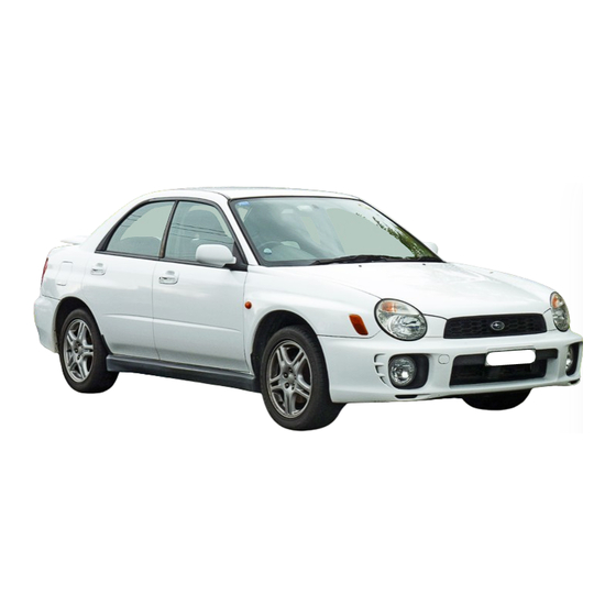
Subaru IMPREZA 2001 Service Manual
Hide thumbs
Also See for IMPREZA 2001:
- Owner's manual (316 pages) ,
- Service manual (189 pages) ,
- Service manual (22 pages)
Table of Contents
Advertisement
Quick Links
2001 IMPREZA SERVICE MANUAL
BODY SECTION
This service manual has been prepared
to provide SUBARU service personnel
with the necessary information and data
for the correct maintenance and repair
of SUBARU vehicles.
This manual includes the procedures
for maintenance, disassembling, reas-
sembling, inspection and adjustment of
components and diagnostics for guid-
ance of experienced mechanics.
Please peruse and utilize this manual
fully to ensure complete repair work for
satisfying our customers by keeping
their vehicle in optimum condition.
When replacement of parts during
repair work is needed, be sure to use
SUBARU genuine parts.
All information, illustration and specifi-
cations contained in this manual are
based on the latest product information
available at the time of publication
approval.
FUJI HEAVY INDUSTRIES LTD.
QUICK REFERENCE INDEX
HVAC SYSTEM
(HEATER, VENTILATOR AND A/C)
HVAC SYSTEM (AUTO A/C)
(DIAGNOSTICS)
AIRBAG SYSTEM
AIRBAG SYSTEM (DIAGNOSTICS)
SEAT BELT SYSTEM
LIGHTING SYSTEM
WIPER AND WASHER SYSTEMS
ENTERTAINMENT
COMMUNICATION SYSTEM
GLASS/WINDOWS/MIRRORS
BODY STRUCTURE
INSTRUMENTATION/DRIVER INFO
SEATS
SECURITY AND LOCKS
IMMOBILIZER (DIAGNOSTICS)
SUNROOF/T-TOP/CONVERTIBLE TOP
(SUNROOF)
EXTERIOR/INTERIOR TRIM
AC
AC
AB
AB
SB
LI
WW
ET
COM
GW
BS
IDI
SE
SL
IM
SR
EI
G1830GE6
Advertisement
Table of Contents

Summary of Contents for Subaru IMPREZA 2001
-
Page 1: Body Section
HVAC SYSTEM (AUTO A/C) (DIAGNOSTICS) AIRBAG SYSTEM AIRBAG SYSTEM (DIAGNOSTICS) This service manual has been prepared to provide SUBARU service personnel SEAT BELT SYSTEM with the necessary information and data for the correct maintenance and repair of SUBARU vehicles. LIGHTING SYSTEM... - Page 2 2001 IMPREZA SERVICE MANUAL QUICK REFERENCE INDEX BODY SECTION EXTERIOR BODY PANELS CRUISE CONTROL SYSTEM CRUISE CONTROL SYSTEM (DIAGNOSTICS) G1830GE6...
-
Page 3: Table Of Contents
CRUISE CONTROL SYSTEM Page General Description ..................2 Actuator.......................3 Cruise Control Module ................4 Cruise Control Main Switch.................5 Cruise Control Command Switch ..............6 Stop and Brake Switch................7 Clutch Switch ....................8 Inhibitor Switch....................9... -
Page 4: General Description
GENERAL DESCRIPTION CRUISE CONTROL SYSTEM 1. General Description A: COMPONENT BO0002 Actuator Cruise control main switch Cruise control module Inhibitor switch (AT) Clutch switch (MT) Cruise control command switch Stop and brake switch B: CAUTION • Connect connectors and hoses securely during reassembly. - Page 5 ACTUATOR CRUISE CONTROL SYSTEM 2. Actuator (B): Must be coated evenly on cam end inner con- nection. A: REMOVAL (C): Cover must be inserted securely, until tip of ca- ble touches cover stopper. CAUTION: • Be careful not to apply excessive load to the wire cable when adjusting and/or installing;...
- Page 6 CRUISE CONTROL MODULE CRUISE CONTROL SYSTEM 3. Cruise Control Module A: REMOVAL 1) Remove side sill front cover. : Hook pawl BO0004 2) Disconnect connector from cruise control mod- ule. 3) Remove the volt, then detach cruise control module. BO0005 B: INSTALLATION Install is in the reverse order of removal.
-
Page 7: Cruise Control Main Switch
CRUISE CONTROL MAIN SWITCH CRUISE CONTROL SYSTEM 4. Cruise Control Main Switch C: INSPECTION A: REMOVAL 1) Remove screws and clip from instrument panel lower cover. 2) Remove instrument panel lower cover. G6M0244 Check continuity between cruise control main switch terminals. Specified condi- Switch position Tester connection... -
Page 8: Cruise Control Command Switch
CRUISE CONTROL COMMAND SWITCH CRUISE CONTROL SYSTEM 5. Cruise Control Command 7) Disconnect horn and cruise control command switch connector, then remove cruise control com- Switch mand switch. A: REMOVAL WARNING: Before servicing, be sure to read the notes in the AB section for proper handling of the driv- er's airbag module. -
Page 9: Stop And Brake Switch
STOP AND BRAKE SWITCH CRUISE CONTROL SYSTEM 6. Stop and Brake Switch A: REMOVAL Disconnect connector from switch, and then re- move the switch. <Ref. to BR-77, REMOVAL, Stop Light Switch.> B: INSTALLATION Install in the reverse order of removal. C: INSPECTION B6M1564A Check continuity brake switch (1) and stop light... -
Page 10: Clutch Switch
CLUTCH SWITCH CRUISE CONTROL SYSTEM 7. Clutch Switch A: REMOVAL Disconnect the connector from the switch, and then remove the switch. <Ref. to CL-34, DISASSEM- BLY, Clutch Pedal.> B: INSTALLATION Install in the reverse order of removal. C: INSPECTION G6M0184 Check continuity between clutch switch terminals. -
Page 11: Inhibitor Switch
INHIBITOR SWITCH CRUISE CONTROL SYSTEM 8. Inhibitor Switch A: REMOVAL Disconnect connector from switch, and then re- move the switch. <Ref. to AT-29, REMOVAL, In- hibitor Switch.> B: INSTALLATION Installation is in the reverse order of removal. C: INSPECTION B6M1530 Check continuity between inhibitor switch termi- nals. - Page 12 INHIBITOR SWITCH CRUISE CONTROL SYSTEM CC-10...


Need help?
Do you have a question about the IMPREZA 2001 and is the answer not in the manual?
Questions and answers