
Related Manuals for GSSI SIR 4000


Summary of Contents for GSSI SIR 4000
- Page 2 Copyright© 2014-2016 Geophysical Survey Systems, Inc. All rights reserved including the right of reproduction in whole or in part in any form Published by Geophysical Survey Systems, Inc. 40 Simon Street Nashua, NH 03060-3075 USA Printed in the United States SIR, RADAN and UtilityScan are registered trademarks of Geophysical Survey Systems, Inc.
- Page 3 OF ITS EQUIPMENT, WHETHER OR NOT DEFECTIVE. Before returning any equipment to GSSI, a Return Material Authorization (RMA) number must be obtained. Please call the GSSI Customer Service Manager who will assign an RMA number. Be sure to have the serial number of the unit available.
-
Page 5: Table Of Contents
2.2: Introduction Screen ....................11 2.3: Setup Collect/Playback Screen ................18 2.4: The Toolbar ........................42 Chapter 3: Setting Up Your SIR 4000 for 2D Data Collection and Playback in Expert Mode ........................... 63 3.1: Setting Up Distance Mode Data Collection ............63 3.2: Setup for Single Line 3D Collection in Expert Mode ........ -
Page 6: Table Of Contents
Geophysical Survey Systems, Inc. SIR® 4000 Manual Appendix A: SIR 4000 System Specifications ..............123 A.1: System Hardware ....................123 A.2: Data Acquisition and Software ................124 A.3: System Includes ....................... 124 Appendix B: The How-To’s of Field Survey ...............125 B.1: Site Selection ......................129 B.2: Targets......................... -
Page 7: Chapter 1: Introduction
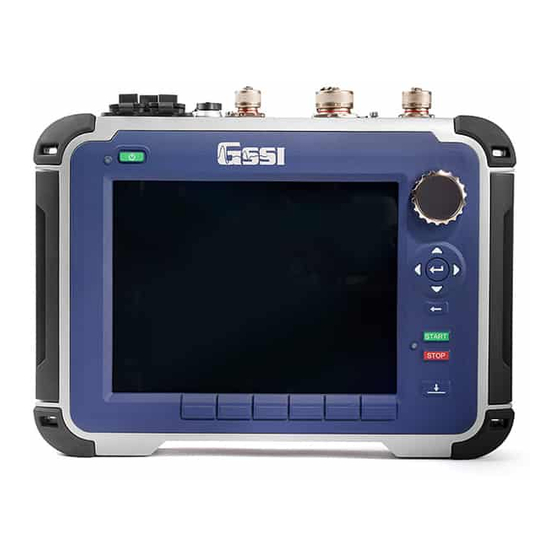
Your choice of antenna, cables, and post-processing software is available for an additional purchase. 1.2: General Description The SIR 4000 is a lightweight, portable, ground penetrating radar system that is ideal for a wide variety of applications and designed to operate GSSI single digital antennas, single analog antennas, or dual frequency antennas. - Page 8 StructureScan Optical: When using either the black pad or the optical reader. RADAN 5 or 6: Data collected with a SIR 4000 is also not compatible with RADAN 5 or 6. You will need RADAN 7 or later version in order to view and process data collected with this system.
- Page 9 Manual Hardware Connections - Top The SIR 4000 has seven connectors located on the top of the unit. Facing the unit from left to right the connectors are: 13 pin Digital Antenna Connection, 19 pin Analog Antenna Connection, External Power, GPIO Connector, HDMI Video Out, Serial Port, and USB 2.0.
- Page 10 Serial I/O (RS232): This is a standard serial connection that can be used to establish communication between the SIR 4000 and a GPS as well as supply power. Please see Chapter 5: Using a GPS with your SIR 4000 for additional information.
- Page 11 SIR 4000. Keypad A built-in keypad, as well as the control knob, will control the SIR 4000. The keypad has sixteen (16) buttons, two (2) indicator lights, and a control knob. All of the keypad button functions will have alternative keyboard implementation, except the Power Button.
- Page 12 SIR® 4000 Manual Power Button: This button turns the SIR 4000 on and off. To start up the system, insert a battery or connect the optional AC power adapter and push the power button. To turn the system off press and hold the power button for approximately four (4) seconds until the screen turns black.
-
Page 13: Cautions And Warnings
The SIR 4000 is factory sealed and no attempt should be made to open it. USB Ports: Do not plug two USB drives into the SIR 4000 at the same time. This includes the USB 2.0 Port and the Micro USM Port. You can have a USB device, such as a keyboard or mouse, plugged in at the same time as USB drive. -
Page 14: Geophysical Survey Systems, Inc. Sir
Geophysical Survey Systems, Inc. SIR® 4000 Manual MN72-433 Rev D... -
Page 15: Hardware Setup
2.1: Hardware Setup Hardware setup for the SIR 4000 is very simple. We will use the 400 MHz (Model 50400S) antenna with single survey wheel for this example. Follow the steps below. Single Survey Wheel Encoder: Attach the survey handle between the two vertical mounting plates on the top of the antenna with the two removable pins, adjust the angle for comfort, and connect the marker cable from the handle to the antenna at the MARK port. - Page 16 Manual Analog Antennas: Connect the female end of the antenna control cable to the antenna. Then connect the male end to the 19 pin analog antenna connection on the back of the SIR 4000. Connect the two protective caps together.
-
Page 17: Introduction Screen
2.2: Introduction Screen After the SIR 4000 boots up and goes past the splash screen, you will see the Introduction screen. This screen allows you to select from the following options and modes. It also includes a toolbar at the bottom and status information. - Page 18 Software Control buttons, located immediately under each icon, will open and close each window. Language There are six (6) language options on the SIR 4000 including English, Japanese, French, Chinese, Portuguese, and Spanish. Use the Control Knob or the Arrow keys to move through the different languages.
- Page 19 Model on the Antenna button and access to the menu will be disabled. This menu is also disabled when no antenna is connected. If an older analog antenna is connected to the SIR 4000 you will be able to select from a list of antenna frequencies.
- Page 20 SIR® 4000 Manual Allows you to configure your SIR 4000 to collect GPS points during data collection. Make the following selections to enable GPS collection. GPS Type: None is set when a GPS is not connected. Custom should be selected if a GPS is connected and needs to be configured.
- Page 21 Theme Select from preformatted color themes for the display on your SIR 4000. Once a theme is selected it will carry through to any of the modules and become the default for the next time you turn the system on.
- Page 22 Select Apply using either the Control Knob or Arrow keys to accept any changes. Firmware: View the current software and firmware installed on the SIR 4000. You can also update the software and firmware from this menu by selecting Update.
- Page 23 Storage This status icon indicates the amount of used memory on the SD card. The SIR 4000 comes with 32 GB of internal memory. The GPS monitor indicates whether or not a GPS is connected and the quality of the GPS signal.
-
Page 24: Setup Collect/Playback Screen
2.3: Setup Collect/Playback Screen The SIR 4000 Setup Screen displays a preview of the data, an Information Bat, Setup Menu, and Toolbar. Information Bar (top): An information bar appears at the very top of the screen and is updated based on whether the SIR 4000 is currently in Collect or Playback Mode. - Page 25 Geophysical Survey Systems, Inc. SIR® 4000 Manual O-Scope (middle): In the middle of the screen you will see a window that shows a single radar scan in an oscilloscope-style (O-scope) depiction. This will show successive single scans as you move your antenna across an area while in the Setup Screen.
- Page 26 Geophysical Survey Systems, Inc. SIR® 4000 Manual Toolbar (bottom): The bar across the bottom of the screen is the Setup or Playback Toolbar and provides different options for modifying how the data appears during setup, collection, or playback. Different Applications will have partially customized or completely redefined Toolbars based upon necessity.
- Page 27 Geophysical Survey Systems, Inc. SIR® 4000 Manual Setup Menu – Radar Under Radar, there are fourteen (14) settings that can each be accessed by rotating the Control Knob or using the Directional Keypad. The settings are: Menu Option Collect Mode Playback Mode Collect Mode Scans/Second...
- Page 28 SIR® 4000 Manual Scans/Second Scans/second is the number of scans the system will collect per second. The SIR 4000 will collect minimum of 4 and maximum of 400 scans/second. • If you are collecting data based on time, this is the number of scans that will be saved each second.
- Page 29 Geophysical Survey Systems, Inc. SIR® 4000 Manual Scans/Unit Scans/unit allows you to adjust the number of scans per unit of horizontal distance. This parameter is the scan spacing when you are collecting with the survey wheel. A unit of measure will appear based on the Units selected from the Introduction Screen and the Horizontal Units selected from the Output Menu.
- Page 30 Modifying Time Range will automatically update the Depth Range. Time Range Time Range is the vertical scale in nanoseconds (ns) within which the SIR 4000 will record reflections. It is proportional to depth viewed because a higher Time Range will allow the energy to penetrate deeper and return deeper reflections.
- Page 31 Geophysical Survey Systems, Inc. SIR® 4000 Manual Effects of Changing Dielectric, Soil Type, Depth Range, or Time Range Changing either Dielectric, Soil Type, Depth Range, or Time Range will affect other settings during setup, data collection, and playback. Below are two charts showing how a change will affect the other settings.
- Page 32 16384. Offset This is an internal system parameter that describes the time lag (in ns) from the SIR 4000 triggering the pulse inside of the control unit until we consider it to have transmitted from the antenna itself. Since there is no way to accurately measure the exact moment the pulse leaves the antenna, we use the antenna’s...
- Page 33 • It is set as a percentage of the total vertical window. The SIR 4000 will examine the offset and the antenna type selected from the Introduction Screen to find the proper surface automatically. It will set near to the first positive peak of the direct wave.
- Page 34 Manual, and then back to Auto, or press the Init button at the bottom of the SIR 4000 keypad. This will cause the system to reset the gains to a lower level to prevent clipping or a higher level to strengthen weak reflections.
- Page 35 Screen. Note: The SIR 4000 is only displaying about 25% of the actual amplitude range. This means that even if your data appears slightly clipped, the SIR® 4000 is likely still recording the full amplitude range of the reflection. If you use a –12 dB display gain, you will see an accurate representation of the recorded scan.
- Page 36 • Determine the length in scans of the feature or noise that you want to remove from the data and input that number in to the SIR 4000. Features, or horizontal reflections, of this size or larger will be removed.
- Page 37 Geophysical Survey Systems, Inc. SIR® 4000 Manual • It is recommended that this filter be set last. When Background Removal is turned on the previewed linescan data and individual scan will gradually be averaged out by the filter and only noise will be visible.
- Page 38 • Determine the length in scans of the feature or noise that you want to remove from the data and input that number in to the SIR 4000. Features, or horizontal reflections, of this size or larger will be removed.
- Page 39 Amplitude Fill Exit Select Datapath This is the location in which your files are stored on the SIR 4000. There are two basic types of paths: Common and User-defined. • Common is the default file path and files in this directory will be named with the word FILE and then a number.
- Page 40 When Select Datapath is pressed using either the Control Knob or the Enter key it opens a list of the different project folders saved on the SIR 4000. Use the Control Knob or Enter key to scroll the list and select a new project folder by pressing the Control Knob or Enter key.
- Page 41 Geophysical Survey Systems, Inc. SIR® 4000 Manual Horizontal Units Sets which units of measure are displayed based on the Units selected from the Introduction Screen. • As an example if you are collecting a long geologic profile you can display the distance in kilometers instead of meters.
- Page 42 Geophysical Survey Systems, Inc. SIR® 4000 Manual Show Hyperbola Toggles a hyperbola On or Off while in setup or during collection. The hyperbola appears at the intersection of the vertical and horizontal cursor. By default the horizontal cursor is placed at the top of the data display.
- Page 43 The scale runs from 0-100% with 100% being the loudest and the sound entirely turned off when set at zero (0). WiFi This menu option toggles the SIR 4000 WiFi On and Off. The WiFi configuration is reserved for future functionality. MN72-433 Rev D...
- Page 44 • When collecting a manual 3D grid without using the SIR 4000 3D grid mode you should set AutoSave to Off. When you finish collecting a transect of data, the file save prompt pauses data collection so that you can reposition to start collecting the next transect.
- Page 45 Press the Start button – This is the green Start button located on the keypad of the SIR 4000. Move antenna to the stop mark – This should match the same location on the antenna or system where you started.
- Page 46 Geophysical Survey Systems, Inc. SIR® 4000 Manual Survey Wheel Factory Default Calibration Settings Note: These default values are provided for convenience, but it is always advisable to calibrate your survey wheel to obtain a more accurate value. These values are recalled when a factory default setting is recalled from Recall Setup.
- Page 47 Geophysical Survey Systems, Inc. SIR® 4000 Manual Note: These default values are provided for convenience, but it is always advisable to calibrate your survey wheel to obtain a more accurate value. These values are recalled when a factory default setting is recalled from Recall Setup. Model 623/624/625 Survey Cart 2-Wheel or 3-Wheel UtilityScan Cart: •...
-
Page 48: The Toolbar
Geophysical Survey Systems, Inc. SIR® 4000 Manual 2.4: The Toolbar The six keys across the bottom of the data display window have different functions depending on whether you are in Setup Collect/Playback Mode, data collection, or data playback. In Setup Collect Mode In Setup Collect Mode, the Toolbar will appear like this: Init(ialize) This button stops and instantly restarts the transmitter. - Page 49 Geophysical Survey Systems, Inc. SIR® 4000 Manual Zoom This option allows you to modify the horizontal scale by zooming in or out by factors of ½x, 1x, 2x, 4x, or 8x. • The system defaults to 1x Zoom on initial startup and when data collection begins. •...
- Page 50 Copy to USB: A way to transfer the files currently selected to a USB drive. The files will be copied, maintaining a copy on the SIR 4000. Move to USB: A way to transfer the files currently selected to a USB drive. The files will be removed from the SIR 4000.
- Page 51 Geophysical Survey Systems, Inc. SIR® 4000 Manual In Setup Playback Mode In Setup Playback Mode, the Toolbar will look like this: Init(ialize) This button initiates the auto gain, which will reset the gain curve based on the quality of the saved data. Gain This Gain option is also referred to as display gain.
- Page 52 Move to Net: A way to transfer the files currently selected to a location on the network. The files will be removed from the SIR 4000. This option will be available in a future update. Move to USB: A way to transfer the files currently selected to a USB drive.
- Page 53 Geophysical Survey Systems, Inc. SIR® 4000 Manual Collect Mode Clicking the Collect control button will bring you back to Setup Collect Mode. You’ll know which mode you’re in by the text displayed in the top left corner of the screen. Playback Mode: Playback Mode –...
- Page 54 Geophysical Survey Systems, Inc. SIR® 4000 Manual • If the dielectric constant is too low when Focus is turned on, hyperbolic reflections will appears in a “U” shape. • Adjusting the dielectric, using the Dielectric control button, will change how hyperbolic reflections appear during data collection.
- Page 55 Geophysical Survey Systems, Inc. SIR® 4000 Manual Gain This Gain option is also referred to as display gain. It increases the amplitude of your data by multiplying every sample throughout your scan by a constant value. The result is that you will be able to better see weaker reflections, but those already strong reflections may be over-gained.
- Page 56 Geophysical Survey Systems, Inc. SIR® 4000 Manual H Cursor You can add a horizontal cursor to the screen during data collection. The yellow line can be toggled On or Off or moved. • To position H Cursor press the H Cursor control button to change the H Cursor to Move. Then use the Control Knob to adjust its position.
- Page 57 Geophysical Survey Systems, Inc. SIR® 4000 Manual • Press the Pause control button to pause data collection. Then press the Dielectric control button. Use the Control Knob to adjust the Dielectric Constant between one (1) and eighty-one (81). The vertical scale will update as the Dielectric Constant is changed. •...
- Page 58 Geophysical Survey Systems, Inc. SIR® 4000 Manual Output - Distance Mode This control button opens a menu with options for modifying the data display during collection. Dielectric: You can adjust the Dielectric Constant during data collection from a value of one (1) to eighty-one (81). •...
- Page 59 Geophysical Survey Systems, Inc. SIR® 4000 Manual Colormap: This menu option offers 30 available Colormap options (i.e. color tables). Select the menu by pressing the Control Knob or Enter key and then scroll through Colormap #0-29. To preview the different Colormaps, if the O-Scope is not displayed during data collection, return to the Setup Screen->Output Menu.
- Page 60 Geophysical Survey Systems, Inc. SIR® 4000 Manual Output - Time Mode This control button opens a menu with options for modifying the data display during collection. Dielectric: You can adjust the Dielectric Constant during data collection from a value of one (1) to eighty-one (81). •...
- Page 61 Geophysical Survey Systems, Inc. SIR® 4000 Manual Output - Point Mode This control button opens a menu with options for modifying the data display during collection. Dielectric: You can adjust the Dielectric Constant during data collection from a value of one (1) to eighty-one (81). •...
- Page 62 Pause/Resume Pauses the data as it is being displayed on the SIR 4000. When the Pause control button is pressed once it stops playback and the control button changes to Resume. The Resume control button can then be pressed to continue playing back the selected data.
- Page 63 Geophysical Survey Systems, Inc. SIR® 4000 Manual Zoom This option allows you to modify the horizontal scale by zooming in or out by factors of ½x, 1x, 2x, 4x, or 8x. • The system defaults to 1x Zoom on initial startup and when data playback begins. •...
- Page 64 Geophysical Survey Systems, Inc. SIR® 4000 Manual Dielectric You can adjust the Dielectric Constant during playback from a value of one (1) to eighty-one (81) . • Changing the Dielectric Constant will change the vertical scale if it is displayed in depth based on the Time Range selected during setup.
- Page 65 Geophysical Survey Systems, Inc. SIR® 4000 Manual Output – Distance and Point Mode This control button opens a menu with options for modifying the data display during playback. Dielectric: You can adjust the Dielectric Constant during data collection from a value of one (1) to eighty-one (81). •...
- Page 66 Geophysical Survey Systems, Inc. SIR® 4000 Manual Toggle Show Hyperbola On or Off by pressing the Control Knob or the Enter key. Colormap: This menu option offers 30 available Colormap options (i.e. color tables). Select the menu by pressing the Control Knob or Enter key and then scroll through Colormap #0-29. To preview the different Colormaps, if the O-Scope is not displayed during data collection, return to the Setup Screen->Output Menu.
- Page 67 Geophysical Survey Systems, Inc. SIR® 4000 Manual Output – Time Mode This control button opens a menu with options for modifying the data display during playback. Dielectric: You can adjust the Dielectric Constant during data collection from a value of one (1) to eighty-one (81). •...
- Page 68 Geophysical Survey Systems, Inc. SIR® 4000 Manual MN72-433 Rev D...
-
Page 69: Expert Mode
Antenna: If not using an antenna with “Smart ID” choose an antenna frequency from the list of available frequencies. GPS: Configure the GPS. Refer to Chapter 7: Using a GPS with your SIR 4000 for instructions on how to configure the GPS. - Page 70 Control knob or Enter button. Note: If you recall a setup after configuring the GPS, the SIR 4000 will recall a baud rate of 4800. If this does not match your previously selected Baud Rate, return to the Introduction Screen and reset your Baud Rate in the GPS Configuration window.
- Page 71 Geophysical Survey Systems, Inc. SIR® 4000 Manual Process Menu Gain Mode and Edit Gain Curve: The thin, red line superimposed over the scan in the O-Scope window is the gain curve. The centerline of the scan is zero and to the left of it is negative (decreasing gain) and the right is positive (increasing gain).
- Page 72 Press the Start button – This is the green Start button located on the keypad of the SIR 4000. Move antenna to the stop mark – This should match the same location on the antenna or system where you started.
-
Page 73: Setup For Single Line 3D Collection In Expert Mode
You will save each profile as a different file and create the 3D project in RADAN’s 3D Module. This method does not use the Quick3D mode on the SIR 4000. For instructions on how to use the control unit to aid in 3D data collection see Chapter 4: Using Quick3D Mode. -
Page 74: Setting Up For Time Mode Data Collection
If 3D imaging is your goal, it is ideal to collect Distance based data with a survey wheel. Step 1 – Introduction Screen Press the green power button and wait for the SIR 4000 Introduction Screen to appear. Expert Mode: Select Expert Mode from the rotating list at the top of the Introduction Screen. - Page 75 SIR® 4000 Manual GPS: Configure the GPS. Refer to Chapter 7: Using a GPS with your SIR 4000 for instructions on how to configure the GPS. New Project: Select New Project and enter in a new Project Name. This will be the name of the folder where all of your files will be stored and the default name of the files as well.
- Page 76 Geophysical Survey Systems, Inc. SIR® 4000 Manual • Target Specific: With the system in Collect Setup mode and data scrolling across the screen, drag the antenna over the area and find a target that you want to image. Note its position on the screen and at what time/depth it occurs.
-
Page 77: Setting Up For Point Mode Data Collection
Stop button for two seconds and you will return to the Collect Setup screen. 3.4: Setting Up for Point Mode Data Collection The third data collection mode on the SIR 4000 is for Point mode data collection. This mode is most useful for deep geophysical investigations or data collection over difficult, broken terrain. - Page 78 Antenna: If not using an antenna with “Smart ID” choose an antenna frequency from the list of available frequencies. GPS: Configure the GPS. Refer to Chapter 7: Using a GPS with your SIR 4000 for instructions on how to configure the GPS.
- Page 79 Geophysical Survey Systems, Inc. SIR® 4000 Manual system so that you’re collecting the maximum range of data possible you’ll want to see some of that noise in the scan trace. If no noise is apparent then you should increase your depth or time range until about 25% of the scan trace is made up of noise.
-
Page 80: Playing Back Collected Data
The SIR4000 operating system includes a feature called Screen Capture. Screen Capture allows you to save a screenshot of the entire SIR 4000 screen and save that image automatically to the SIR4000 memory as a Portable Network Graphics (.PNG) file. A .PNG file is a “picture” file that you can email to the client or print off. - Page 81 Up arrow once. Screen Capture works in either Collect or Playback mode. You will hear an audio indication that the SIR 4000 has saved the screen capture. Screen Capture Image: The SIR4000 screen capture feature will save the entirety of the image that is currently on the screen.
- Page 82 Geophysical Survey Systems, Inc. SIR® 4000 Manual MN72-433 Rev D...
-
Page 83: Chapter 4: Using Quick3D Mode
3D data collection. During the survey, each individual radar profile is saved as it is collected. At the end of the grid, the SIR 4000 creates a special folder and file which contain positioning information. This information is then used by RADAN to quickly build and display the 3D data. You can also view the 3D data on the SIR 4000 after collection and perform some processing functions such as applying FIR/IIR Filters or performing Hyperbola Fitting. -
Page 84: Setting Up A Physical 3D Grid
Geophysical Survey Systems, Inc. SIR® 4000 Manual 4.2: Setting Up a Physical 3D Grid Collecting data for 3D processing and interpretation is easiest when there is a physical guide grid laid out to follow. Grids can be laid out using chalk, paint, measuring tapes, ropes, or some other method. A grid can be any size, but data quality is better if the grid corners are square. -
Page 85: Setting Up Quick3D Collection
Manual 4.3: Setting Up Quick3D Collection Quick3D mode on the SIR 4000 has the same menus as Expert Mode described in Chapter 2, plus an additional menu to setup the size and collection parameters for a 3D grid. Grid Menu X/Y Start Value: These two items tell the system the coordinate of your origin point. -
Page 86: Step By Step Quick3D Setup
Geophysical Survey Systems, Inc. SIR® 4000 Manual X/Y Line Order: This controls the survey line direction. • Forward: Profiles are surveyed in one direction from the starting baseline to the ending baseline. At the end of each profile, you must move the antenna back to the starting baseline before moving to the next line and collecting in the same direction. - Page 87 Rotate the Control Knob or use the up and down arrows to enter in the correct value. Click the right arrow to save and exit. Note: The SIR 4000 saves the survey wheel encoder calibration value in counts/meter no matter your selected units of measure. That means that if you are used to working in English (Imperial) units and are familiar with a Model 620 tow-behind wheel calibration value of ~127/ft, the new calibration value you will see will be ~417.
- Page 88 Step 5: Enter Collection Screen Once you are satisfied with the grid and settings press the green Start button on the SIR 4000. This will open the 3D Collection Screen. There are four different ways to view the 2D profiles and 3D slice maps during collection and you can toggle through them by pressing the View Toggle control button.
-
Page 89: Collecting 3D Data
Geophysical Survey Systems, Inc. SIR® 4000 Manual • Grid Display: Shows the full 3D grid and your current location within the grid. There are three views in this display. • 2D Profile: Shows just the 2D profile and can be used to perform a hyperbola fitting on the data. - Page 90 After traveling the distance that you specified in 3D Setup, the SIR 4000 will automatically stop collecting data. The file will save and the system will automatically increment to the next line.
- Page 91 Geophysical Survey Systems, Inc. SIR® 4000 Manual Step 3: Recollecting or Skipping Lines If you need to skip or redo a line, use Next Line or Previous Line to move around the grid. You will see the yellow line move to indicate your current position.
- Page 92 Geophysical Survey Systems, Inc. SIR® 4000 Manual Press the red Stop button. This will end the line and shift it so that it lines up with the opposite baseline. Step 5: Saving the Grid When you are finished collecting in either the X-Direction, Y-Direction, or both press and hold the red Stop button.
-
Page 93: Modify The 3D Display During Collection
Geophysical Survey Systems, Inc. SIR® 4000 Manual 4.6 Modify the 3D Display during Collection You can adjust how the data appear during data collection using the Toolbar soft keys and the Output menu available in the 3D Collection Screen. View Toggle: Pressing this soft key toggles the 3D Collection Screen between a top down view of the grid and 3D view of the grid. - Page 94 Geophysical Survey Systems, Inc. SIR® 4000 Manual Output Menu This menu provides options for modifying the appearance of your data during collection. The first six (6) options are the same for 3D collection as they are for 2D collection. None of these setting affect the raw data. H Cursor: Changes the depth of the slice map in the Grid Display in half inch increments.
-
Page 95: Gps Enabled 3D Collection
Step 3: Monitor GPS Quality When you start collecting each 2D profile in your 3D grid, the SIR 4000 captures a GPS coordinate and place it in the file header. It will continue capturing positions every three (3) seconds until you end data collection as long as the HDOP is two (2) or less. -
Page 96: Quick3D Playback
Geophysical Survey Systems, Inc. SIR® 4000 Manual 4.8 Quick3D Playback Quick3D Playback allows the user to display previously collected 3D data as a grid or in 2D profiles, recollect data within a previously collected grid, and modify some settings used during the original data collection. - Page 97 Geophysical Survey Systems, Inc. SIR® 4000 Manual Quick3D Playback Options The Playback Screen allows you to view individual 2D profiles in a grid format, rotate the grid to view data from different angles, apply filters, change colors, and do hyperbola fitting. If you’re still in the field you also have the ability to recollect lines in the grid.
- Page 98 Geophysical Survey Systems, Inc. SIR® 4000 Manual • To modify Gain press the Gain control button and use either the Control Knob or Right/Left Arrow keys to adjust the gain amount. • Display Gain is only for display and is not saved with the data. Fence X and Y Profiles that were collected in either the X or Y direction or both can be viewed...
- Page 99 Geophysical Survey Systems, Inc. SIR® 4000 Manual Rotate You can adjust the rotation of the 3D grid using either a soft key or from the Output Menu. To adjust simply press the Rotate soft key and use the Control Knob of rotate the grid on a 360º axis. Output This control button opens a menu with options for modifying the data display during playback.
- Page 100 Geophysical Survey Systems, Inc. SIR® 4000 Manual Color Slide: Selecting Color Slide allows you to shift the center point of the selected Colormap over a scan’s amplitude range. A negative number shifts towards the positive amplitudes and positive number shifts towards the negative amplitudes. •...
-
Page 101: Structurescan2D
Chapter 5: Summary of Pre-Set Mode Parameters This section briefly describes the pre-set operation modes for the SIR 4000. These modes are more limited in their customization because they are meant for specific applications or to collect data for on- screen target location as opposed to post-processing. - Page 102 Geophysical Survey Systems, Inc. SIR® 4000 Manual StructureScan2D Setup Select StructureScan2D from the modes at the top of the Introduction screen. If using a Smart Antenna, such as the 52600S, the correct antenna will be selected. However, if using an older antenna you’ll need to select the correct frequency from the Antenna soft key at the bottom of the screen.
- Page 103 Geophysical Survey Systems, Inc. SIR® 4000 Manual Dielectric: You can adjust the Dielectric value of your concrete manually if you know it from a previous survey. Otherwise use Concrete Type to set the Dielectric. Concrete Type: This sets the dielectric constant and gives you a more accurate depth calculation.
- Page 104 Press the Stop button – This is the red Stop button located on the keypad of the SIR 4000. Repeat Steps b)-e) at least twice to ensure that you get consistent calibration values.
- Page 105 Geophysical Survey Systems, Inc. SIR® 4000 Manual StructureScan2D Data Collection Holding the Dead-Man Switch, press the green Start button. This will start data collection. Continuing to hold the Dead-Man Switch, move the antenna forward over the line you’re surveying. At the end of your file, press the red Stop button one time.
- Page 106 Geophysical Survey Systems, Inc. SIR® 4000 Manual Options during Collection As you collect a line along the slab you’ll have several ways to calibrate the system and change the display. Gain This Gain option is also referred to as display gain. It increases the amplitude of your data by multiplying every sample throughout your scan by a constant value.
- Page 107 Geophysical Survey Systems, Inc. SIR® 4000 Manual H Cursor You can add a horizontal cursor to the screen during data collection. The yellow line can be toggled On or Off or moved. • To position H Cursor press the H Cursor control button to change the H Cursor to Move.
- Page 108 Playback will save when you exit. • Pause/Resume - Pauses the data as it is being displayed on the SIR 4000. When the Pause control button is pressed once it stops playback and the control button changes to Resume. The Resume control button can then be pressed to continue playing back the selected data.
-
Page 109: Structurescan3D
Geophysical Survey Systems, Inc. SIR® 4000 Manual o Colormap: This menu option offers 30 available Colormap options (i.e. color tables). Select the menu by pressing the Control Knob or Enter key and then scroll through Colormap #0-29. o File Info: This opens a window showing the current settings including Radar Parameters, Positioning information, and Processing History. - Page 110 StructureScan3D File Structure StructureScan3D mode creates a folder on your SIR 4000 with the name of the grid followed by the extension 3DS. Inside of that folder are all of the DZT files, DZX files, and a file with the extension BZX.
- Page 111 • The project folder will also contain a subfolder called Proc. This folder contains DZP files that are used to playback the 3D data on the SIR 4000. They are not necessary for 3D viewing or processing in RADAN. Note: You must keep that BZX file •...
- Page 112 Geophysical Survey Systems, Inc. SIR® 4000 Manual • Grid Display: Shows the full 3D grid and your current location within the grid. There are three views in this display. • 2D Profile: Shows just the 2D profile and can be used to perform a hyperbola fitting on the data.
- Page 113 Geophysical Survey Systems, Inc. SIR® 4000 Manual Step 8: Continue Collection Move the antenna to the beginning of Line 2 and center it over the baseline. Press the green Start button or the marker button on the cart (or antenna if using the 2 GHz Palm) to collect the next line. Repeat these steps until you’ve finished collecting lines in both the X and Y Directions.
- Page 114 Geophysical Survey Systems, Inc. SIR® 4000 Manual Adding a Line Segment You can collect portions of a line or stop and start collection along a line by using the Add Segment button. There are two ways to use this button. Offset the Starting Position: You can choose to start away from the baseline if needed.
- Page 115 Geophysical Survey Systems, Inc. SIR® 4000 Manual Modify the 3D Display during Collection You can adjust how the data appear during data collection using the Toolbar soft keys and the Output menu available in the 3D Collection Screen. View Toggle: Pressing this soft key toggles the 3D Collection Screen between a top down view of the grid, askew angle showing the 2D profiles and 3D view of the grid simultaneously, just the 2D profile, and the 2D profile view for hyperbola fitting.
- Page 116 Geophysical Survey Systems, Inc. SIR® 4000 Manual Home: Resets Rotate and Viewpoint back to zero (0). Marks on Grid: This turns the grid marks on or off. Grid marks correspond with the location of the profiles in the grid. Only adds marks to the lines where data have already been collected.
- Page 117 Geophysical Survey Systems, Inc. SIR® 4000 Manual StructureScan3D Playback Options The Playback Screen allows you to view individual 2D profiles in a grid format, rotate the grid to view data from different angles, change colors, and do hyperbola fitting. These options are all available through the Toolbar located at the bottom of the screen.
- Page 118 Geophysical Survey Systems, Inc. SIR® 4000 Manual Gain This Gain option is also referred to as display gain. It increases the amplitude of your data by multiplying every sample throughout your scan by a constant value. The result is that you will be able to better see weaker reflections, but those already strong reflections may be over- gained.
- Page 119 Geophysical Survey Systems, Inc. SIR® 4000 Manual Scan Cursor Selecting Scan Cursor allows you to adjust the location of the Horizontal slice (H Cursor) in your grid or a Vertical line (Scan Cursor) along the currently selected profile. This can be used to acquire more accurate depth and distance information.
- Page 120 Geophysical Survey Systems, Inc. SIR® 4000 Manual H Cursor: Changes the depth of the slice map in the Grid Display in half inch increments. Slice Thickness: Adjusts the slice thickness from zero (0) inches to the maximum selected depth range in half inch increments.
-
Page 121: Chapter 6: Data Transfer And File Maintenance
To copy the files to the USB memory stick and remove them from the SIR 4000 press the Move to USB Command key. A progress bar will appear on the screen showing the status of the copied files. - Page 122 Geophysical Survey Systems, Inc. SIR® 4000 Manual Press the Delete Files control button. A progress bar will appear on the screen showing the status of the copied files. Deleting Project Folders From either the Collect or Playback Setup screen open Output->Select Datapath. Select the data path you wish to delete.
-
Page 123: Chapter 7: Using A Gps With Your Sir 4000
Format: Choose a format for viewing the data during collection and playback. When you start collecting a file, the SIR 4000 will capture a GPS coordinate and place it in the file header. It will do the same every three (3) seconds as long as you are collecting data and the HDOP (Horizontal Dilution of Precision) is two (2) or less. -
Page 124: Understanding Gps
7.2: Understanding GPS This is a brief description of GPS and how to use it with our SIR 4000. GPS information gets attached to the data as a *.DZG file, which RADAN 7 incorporates into its database automatically when the *.DZT file is opened. -
Page 125: What Is The Dzg File
Rover position. 7.3 What is the DZG File? The GPS file collected with the SIR 4000 is identified by the extension *.DZG and consists of multiple two-sentence blocks. First sentence (line) starting with $GSSIS contains the DZT file scan (trace number) associated with the GPS location. - Page 126 Geophysical Survey Systems, Inc. SIR® 4000 Manual $GPGGA,150527.00,4713.46473386,N,06817.13641152,W,2,10,1.0,185.206,M,-26.675,M,4.0,0138*7D Scan Count at File Scan 0 = 1648470 Scan Count at File scan 16 = 1648784 Scan Count at File scan 42 = 1649257 Time at scan 16 relative to scan 0 = (1648784 – 1648470)/473 = 0.66 seconds Time at scan 42 relative to scan 0 = (1649257–...
-
Page 127: What Is Waas
Geophysical Survey Systems, Inc. SIR® 4000 Manual 7.4 What is WAAS? The Wide Area Augmentation System (WAAS) is a form of differential GPS that uses geostationary satellites to transmit an error correction estimate back down to your receiver. The measured positions of ground reference stations, strategically positioned across the country, are sent up to the WAAS satellites. - Page 128 Geophysical Survey Systems, Inc. SIR® 4000 Manual MN72-433 Rev D...
-
Page 129: Appendix A: Sir 4000 System Specifications
Geophysical Survey Systems, Inc. SIR® 4000 Manual Appendix A: SIR 4000 System Specifications A.1: System Hardware Antennas: Compatible with all GSSI Antennas Number of Channels: 1 (one) Data Storage: Internal memory 32 GB Processor: NVidia Tegra 3 Display: Enhanced 10.4” LED, 1024 by 768 resolution and 32-bit color... -
Page 130: A.2: Data Acquisition And Software
A.3: System Includes Digital Control Unit (DC-4000) with preloaded operating system (1) Transit Case (1) Batteries (2) Charger (1) Sunshade (1) Operation Manual (1) GSSI Manual CD (1) Fully FCC , RSS-220, and CE Compliant. MN72-433 Rev D... - Page 131 Download the latest version of software and instructions from the GSSI support website to your https://support.geophysical.com. computer. Unzip the folder to the GSSI 2GB USB drive supplied with your SIR 4000. By double-clicking on the *.zip file, Windows will automatically open whichever compression software you have installed. Note:...
- Page 132 Copy all of the subfolders and files to the main directory of your USB drive. With the SIR 4000 powered on and on the Introduction Screen, plug the USB drive into your SIR 4000. The GSSI software will close and the upload will automatically begin. Once the file upload is complete the SIR 4000 will reboot.
- Page 133 100% and disappears, the firmware update is finished. Reboot the SIR 4000 (Press and hold the green Power button for 3 seconds to turn the unit off, then press the Power button to turn the unit back on).
- Page 134 Geophysical Survey Systems, Inc. SIR® 4000 Manual MN72-433 Rev D...
-
Page 135: B.1: Site Selection
Geophysical Survey Systems, Inc. SIR® 4000 Manual Appendix C: The How-To’s of Field Survey As the old saying goes: “Garbage in, Garbage out”. The biggest single factor affecting the quality of your data and your ability to make decisions based on it, is the accuracy of your data collection. This appendix has instructions and helpful hints to get you into the habit of collecting quality data from the beginning. -
Page 136: B.2: Targets
Geophysical Survey Systems, Inc. SIR® 4000 Manual Subsurface Conditions If you are working with concrete, try to make sure that the concrete has had some curing time. Three months is usually adequate for a standard slab on grade, while a suspended slab may cure faster. The best solution is to practice on slabs of different ages so that you have a first-hand feel of the way they will look. - Page 137 For utility and tank location, we usually recommend 6-24/ft. While this is more than the minimum rule of thumb, GSSI has found these densities to work well in the widest variety of situations. The image above shows hyperbolas from objects of similar size. The hyperbolas vary in size because, due to the spreading of the radar signal, a deeper target shows reflections in more scans than a shallow one.
-
Page 138: B.3: Data Collection Methods: 2D Vs. 3D
Geophysical Survey Systems, Inc. SIR® 4000 Manual Lower frequency antennas, like the 200 MHz and 400 MHz, will “Hazy” Zone sometimes not image targets close to the surface very well. While not Frequency Inches (cm) strictly a ‘dead zone’ you should be aware that it may be difficult (but not impossible!) to see targets in this area. - Page 139 Geophysical Survey Systems, Inc. SIR® 4000 Manual Collecting data for 3D imaging obviously takes more time than 2D collection. While the SIR(R) 4000 makes it faster and easier than it has ever been before, it can still add significant time (and cost) to a job. It also requires some software processing to produce an interpretable image.
- Page 140 Geophysical Survey Systems, Inc. SIR® 4000 Manual MN72-433 Rev D...
- Page 141 Geophysical Survey Systems, Inc. SIR® 4000 Manual Appendix D: Dielectric Values For Common Materials Material Dielectric Material Dielectric Constant Constant Wet Granite Snow Firn Travertine Dry Loamy/Clayey Soils Wet Limestone Dry Clay Wet Basalt Dry Sands Tills Wet Concrete 12.5 Coal Volcanic Ash Asphalt...
- Page 142 Geophysical Survey Systems, Inc. SIR® 4000 Manual MN72-433 Rev D...
-
Page 143: D.1: Preloaded Setups In Expert Mode
Manual Appendix E: Listing of Antenna Parameters The SIR 4000 comes with preloaded setups to fit the system’s data collection parameters and filters to the most commonly used, currently available GSSI antennas. Settings for additional antennae are also provided below to assist you in creating a setup for an older or specialized antenna. Please note that these are only generalized setups, and it may be necessary to alter these to your particular situation. - Page 144 Geophysical Survey Systems, Inc. SIR® 4000 Manual 1.5/1.6 GHz (Model 5100S) 1.5 GHz ground coupled antenna. Depth of viewing window is approximately 18 inches in concrete. Setting is optimized for scanning of structural features in concrete. Range: 12 ns Samples per Scan: 512 Resolution: 32 bits Number of gain points: 5 Vertical High Pass Filter: 250 MHz...
- Page 145 Geophysical Survey Systems, Inc. SIR® 4000 Manual 270 MHz (Model 50270S) 270 MHz ground coupled antenna. Depth of viewing window is approximately 4m assuming a dielectric constant of 5. Range: 75 ns Samples per Scan: 512 Resolution: 32 bits Number of gain points: 3 Vertical High Pass Filter: 75 MHz Vertical Low Pass Filter: 700 MHz Scans per second: 120...
-
Page 146: D.2: Parameter Listing For Older/Specialty Antennae
Deep or Shallow prospecting. Please note that many of these antennae have a different listed transmit rate than the default one on the SIR 4000. The transmit rate listed here is the rate that the antenna was tested and rated at. It may function correctly at a higher transmit rate and allow you to collect data faster, but you must pay careful attention to your data to decide if the antenna is functioning correctly at the different rate. - Page 147 Geophysical Survey Systems, Inc. SIR® 4000 Manual 120-Shallow-Unshielded 80 MHz 120 MHz standard antenna. 80 MHz folded bow-tie antenna. Note: The 80 MHz antenna is unshielded. Data Collection Mode: Continuous Range: 200ns Data Collection Mode: Continuous Samples per Scan: 512 Range: 500ns Resolution: 32 bits Samples per Scan: 512...
- Page 148 Geophysical Survey Systems, Inc. SIR® 4000 Manual MLF 360 cm Borehole 120 MHz Low Frequency antenna length 3.6m Borehole antenna frequency 120 MHz. Note: The borehole antennas are unshielded. Data Collection Mode: Point Range: 750ns Data Collection Mode: Point Samples per Scan: 512 Range: 500ns Resolution: 32 bits Samples per Scan: 512...
- Page 149 Geophysical Survey Systems, Inc. SIR® 4000 Manual Appendix F: Glossary of Terms and Suggestions for Further Reading Antenna: a paired transmitter and receiver that sends electromagnetic energy into a material and receives any reflections of that energy from materials in the ground. Also called a transducer. Antennae are commonly referred to by their center frequency value (i.e.
- Page 150 Geophysical Survey Systems, Inc. SIR® 4000 Manual Migration: mathematical calculation used to remove outlying tails of a hyperbola and to accurately fix the position of a target. Nano-second: unit of measurement for recording the time delay between transmission of a radar pulse and reception of that pulse’s reflections.
- Page 151 Geophysical Survey Systems, Inc. SIR® 4000 Manual Further Reading Butler Dwain, K., Ed. 2005 Near-Surface Geophysics. Society of Exploration Geophysicists, Tulsa, OK. Daniels, David J. 2004 Ground Penetrating Radar, Second Edition. The Institution of Electrical Engineers, London, United Kingdom. Conyers, Lawrence B. 2004 Ground-Penetrating Radar for Archaeology, Third Edition, Altamira Press, Boulder, CO.
- Page 152 Geophysical Survey Systems, Inc. SIR® 4000 Manual Useful Websites: Geophysical Survey Systems, Inc.: www.geophysical.com United States Department of Agriculture Soils Website: http://soils.usda.gov/ USDA-Natural Resources Conservation Service, Ground Penetrating Radar Program: http://nesoil.com/gpr/ USDA – Natural Resources Conservation Service, GPR Soil Suitability http://www.nrcs.usda.gov/wps/portal/nrcs/detail/soils/use/maps/?cid=nrcs142p2_053622 USDA-Natural Resources Conservation Service, Web Soil Survey http://websoilsurvey.sc.egov.usda.gov/App/HomePage.htm...
Need help?
Do you have a question about the SIR 4000 and is the answer not in the manual?
Questions and answers