Table of Contents
Advertisement
Quick Links
Advertisement
Table of Contents

Related Manuals for GSSI SIR 4000


Summary of Contents for GSSI SIR 4000
- Page 2 Copyright© 2014-2017 Geophysical Survey Systems, Inc. All rights reserved including the right of reproduction in whole or in part in any form Published by Geophysical Survey Systems, Inc. 40 Simon Street Nashua, NH 03060-3075 USA Printed in the United States SIR, RADAN, UtilityScan, PaveScan are registered trademarks of Geophysical Survey Systems, Inc.
- Page 3 OF ITS EQUIPMENT, WHETHER OR NOT DEFECTIVE. Before returning any equipment to GSSI, a Return Material Authorization (RMA) number must be obtained. Please call the GSSI Customer Service Manager who will assign an RMA number. Be sure to have the serial number of the unit available.
-
Page 5: Table Of Contents
Chapter 5: Summary of Pre-Set Mode Parameters ............75 5.1: StructureScan2D ......................75 5.2: StructureScan3D ......................83 Chapter 6: Setting Up Your SIR 4000 for | 2D Data Collection and Playback in Digital 2D Mode ..........................93 6.1: Setting Up Distance Mode Data Collection ............93 6.3: Setting Up for Time Mode Data Collection in Digital 2D ...... - Page 6 Geophysical Survey Systems, Inc. SIR® 4000 Manual Chapter 7: Setting Up Your SIR 4000 for 3D Data Collection and Playback in Digital 3D Mode ..........................111 7.1: Digital 3D File Structure ..................111 7.2: Setting Up a Physical 3D Grid ................112 7.3: Setting Up Digital 3D Collection ................
-
Page 7: Chapter 1: Introduction
Your choice of antenna, cables, and post-processing software is available for an additional purchase. 1.2: General Description The SIR 4000 is a lightweight, portable, ground penetrating radar system that is ideal for a wide variety of applications. It is designed to operate GSSI single digital antennas, single analog antennas, or dual frequency antennas. - Page 8 StructureScan Optical: When using either the black pad or the optical reader. RADAN 5 or 6: Data collected with a SIR 4000 is not compatible with RADAN 5 or 6. You will need RADAN 7 or a later version in order to view and process data collected with the SIR 4000.
- Page 9 Serial I/O (RS232): This is a standard serial connection that can be used to establish communication between the SIR 4000 and a GPS as well as supply power. Please see Chapter 7: Using a GPS with your SIR 4000 for additional information.
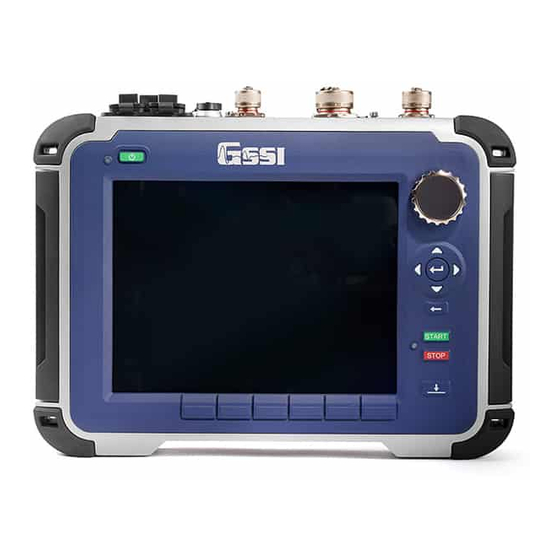
- Page 10 Power Button. Power Button: This button turns the SIR 4000 on and off. To start up the system, insert a battery or connect the optional AC power adapter and push the green power button. To turn the system off press and hold the power button for approximately four (4) seconds until the screen turns black.
- Page 11 Geophysical Survey Systems, Inc. SIR® 4000 Manual Power Status LED: When the system is turned on the indicator light will flash red. When the system is ready the LED will remain a solid red. Control Knob: Cycles through the menu tree, quickly changes numeric values, and makes selections. •...
-
Page 12: Cautions And Warnings
Software Control Buttons: Six (6) buttons are located below the display screen and change function depending upon the current mode in use on the SIR 4000. For a list of each function see Chapter 2: Getting Started and Expert Mode Setup. -
Page 13: Chapter 2: Getting Started And Expert Mode Setup
PC for processing in GSSI’s RADAN post-processing software. 2.1: Hardware Setup Hardware setup for the SIR 4000 is very simple. As an example we will use the 400 MHz (Model 50400S) antenna with single survey wheel. Follow the steps below. - Page 14 Manual Digital Antennas: Connect the female end of the antenna cable to the antenna. Then connect the male end to the 13 pin digital antenna connection on the back of the SIR 4000. Connect the two protective caps together. Digital...
-
Page 15: Introduction Screen
2.2: Introduction Screen After the SIR 4000 boots up and goes past the splash screen, you will see the Introduction screen. This screen allows you to select from the following options and modes. It also includes a toolbar at the bottom and status information. - Page 16 Software Control buttons, located immediately under each icon, will open and close each window. Language There are six (6) language options on the SIR 4000 including English, Japanese, French, Chinese, Portuguese, and Spanish. Use the Control Knob or the Arrow keys to move through the different languages.
- Page 17 Model on the Antenna button and access to the menu will be disabled. This menu is also disabled when no antenna is connected. If an older analog antenna is connected to the SIR 4000 you will be able to select from a list of antenna frequencies.
- Page 18 Select the Baud Rate that matches the one set on your GPS. Press the green Start button on the right side of the SIR 4000. Wait for the GPS to acquire enough satellites and accuracy so that the HDOP is 2 or less.
- Page 19 SIR® 4000 Manual Theme Select from preformatted color themes for the display on your SIR 4000. Once a theme is selected it will carry through to any of the modules and become the default for the next time you turn the system on.
-
Page 20: Setup Collect/Playback Screen
Red Battery: Less than 15 minutes remain. Battery icon will continue to pulse; replace battery. Storage Indicates the amount of used memory on the SD card. The SIR 4000 has 32 GB of internal memory. The GPS monitor indicates whether or not a GPS is connected and the quality of the GPS signal. - Page 21 Geophysical Survey Systems, Inc. SIR® 4000 Manual Information Bar O-Scope Toolbar Main Data Display (left): The main data display window shows a radar profile in linescan format. Successive single scans are assigned color values based on amplitude change and displayed next to each other in sequence to form a continuous image.
- Page 22 Dielectric Scans/Second Soil Type Scans/second is the number of scans the system will collect per Depth Range second. The SIR 4000 will collect minimum of 4 and Time Range maximum of 400 scans/second. Position Mode • If you are collecting time-based data, this is the Offset number of scans that will be saved each second.
- Page 23 If you set Scans/Second higher than the selected transmit rate and the number of samples/scan, the SIR 4000 will lower it to the maximum possible. However, it is recommended that the scans/second be set lower than the maximum. This will allow the system to auto stack points thereby improving the signal to noise ratio.
- Page 24 Modifying Time Range will automatically update the Depth Range. Time Range Time Range is the vertical scale in nanoseconds (ns) within which the SIR 4000 will record reflections. It is proportional to depth viewed because a higher Time Range will allow the energy to penetrate deeper and return deeper reflections.
- Page 25 0 ns based on the Surface % selected. Auto: Anytime the antenna is re-initialized, as when pressing the Init button or first entering the Setup Collect Screen, the SIR 4000 will set the Position automatically. • For most applications and surveys, to acquire an accurate Position using Auto Mode the antenna should be placed on the surface to be scanned prior to entering the Setup Collect Screen.
- Page 26 • It is set as a percentage of the total vertical window. The SIR 4000 will examine the offset and the antenna type selected from the Introduction Screen to automatically find the proper surface. It will set near to the first positive peak of the direct wave.
- Page 27 Manual, and then back to Auto, or press the Init button at the bottom of the SIR 4000 keypad. This will cause the system to reset the gains to a lower level to prevent clipping or a higher level to strengthen weak reflections.
- Page 28 Press the Control Knob or Enter key a second time to save and deselect the modified gain point. Note: The SIR 4000 is only displaying about 25% of the actual amplitude range. This means that even if your data appears slightly clipped, the SIR® 4000 is likely still recording the full amplitude range of the reflection.
- Page 29 Geophysical Survey Systems, Inc. SIR® 4000 Manual FIR Low Pass and IIR High Pass These options, and the following seven (7), allow you to set data collection filters to either remove interference or smooth noise. A Low or High Pass filter is an antenna-specific frequency filter and should be modified each time a different antenna is connected.
- Page 30 Geophysical Survey Systems, Inc. SIR® 4000 Manual Horizontal Noise to be Filter length should be set to the number of scans equal to the feature Removed length to be removed. Any continuous feature within the data, such as a water table reflector or a stratigraphic boundary between two soil types, may also be filtered out by performing Background Removal.
- Page 31 • Determine the length in scans of the feature or noise that you want to remove from the data and input that number in to the SIR 4000. Features, or horizontal reflections, of this size or larger will be removed.
- Page 32 Geophysical Survey Systems, Inc. SIR® 4000 Manual Signal Floor When Signal Floor is turned on it overlays a green field on the Linescan display. This green field is an estimate of the effective depth of each scan based on an analysis of the noise to signal loss (attenuation).
- Page 33 Geophysical Survey Systems, Inc. SIR® 4000 Manual Select Datapath This is the location in which your files are stored on the SIR 4000. There are two basic types of paths: Common and User-defined. • Common is the default file path...
- Page 34 Geophysical Survey Systems, Inc. SIR® 4000 Manual Vertical Units Sets which units of measure are displayed based on which Vertical Scale is currently selected. • As an example: if you are using a very high frequency antenna to scan 18 inches into concrete, you may choose to display depth in inches instead of feet.
- Page 35 Geophysical Survey Systems, Inc. SIR® 4000 Manual Show O-Scope Toggles the O-Scope display On or Off for use during data collection. Selecting Off will not turn off the O-Scope display in the Setup Screen. • During data collection you will not have the option to turn the O-Scope display On or Off.
- Page 36 Geophysical Survey Systems, Inc. SIR® 4000 Manual Color Slide Selecting Color Slide allows you to shift the center point of the selected Colormap over a scan’s amplitude range (amplitude zero crossing). A negative number shifts towards the positive amplitudes and positive number shifts towards the negative amplitudes.
- Page 37 • When collecting a manual 3D grid without using the SIR 4000 3D grid mode you should set AutoSave to Off. When you finish collecting a transect of data, the file save prompt pauses data collection so that you can reposition to start collecting the next transect.
- Page 38 Press the Start button – This is the green Start button located on the keypad of the SIR 4000. Move antenna to the stop mark – This should match the same location on the antenna or system where you started.
- Page 39 Geophysical Survey Systems, Inc. SIR® 4000 Manual Survey Wheel Factory Default Calibration Settings Note: These default values are provided for convenience, but it is always advisable to calibrate your survey wheel to obtain a more accurate value. These values are recalled when a factory default setting is recalled from Recall Setup.
-
Page 40: The Toolbar
Geophysical Survey Systems, Inc. SIR® 4000 Manual 2.4: The Toolbar The six keys across the bottom of the data display window have different functions depending on whether you are in Setup Collect/Playback Mode, data collection, or data playback. In Setup Collect Mode In Setup Collect Mode, the Toolbar will appear like this: Init(ialize) This button stops and instantly restarts the transmitter. - Page 41 USB drive. The files will only be copied; the original files will remain on the SIR 4000. Move to USB: A way to transfer currently selected files to a USB drive. The files will be removed from the SIR 4000.
- Page 42 Manual Delete Files: Deletes the currently selected files from the project folder. If all of the files are selected and deleted the SIR 4000 will still keep the project folder. File Info This control button opens a window showing the current settings including Radar Parameters, Positioning information, and Processing History.
- Page 43 Move to Net: A way to transfer the files currently selected to a location on the network. The files will be removed from the SIR 4000. This option will be available in a future update. Move to USB: A way to transfer the files currently selected to a USB drive. The files will be removed from the SIR 4000.
- Page 44 Geophysical Survey Systems, Inc. SIR® 4000 Manual • If the dielectric constant is too high when Focus is turned on, hyperbolic reflections will still appear as hyperbolas. • If the dielectric constant is too low when Focus is turned on, hyperbolas will appear in a “U”...
- Page 45 Geophysical Survey Systems, Inc. SIR® 4000 Manual • To position H Cursor press the H Cursor control button to change the H Cursor to Move. Then use the Control Knob to adjust its position. Rotate the knob left (counter- clockwise) to move the cursor down the time range.
- Page 46 Geophysical Survey Systems, Inc. SIR® 4000 Manual Set Depth This control button allows you to enter the depth of a known target and automatically adjust the Dielectric Constant. This option is only available when Show Hyperbola is turned off. This can either be done from Setup or while collecting through the Output control button.
- Page 47 Geophysical Survey Systems, Inc. SIR® 4000 Manual A Hilbert Transform will change a radar signal represented as a time series into its magnitude (via envelope detection) phase). The Hilbert Transform expresses the relationship between the phase and magnitude of the signal, or between its real and imaginary parts.
- Page 48 Geophysical Survey Systems, Inc. SIR® 4000 Manual Left Color Slide = -0.20; Middle Color Slide = 0; Right Color Slide = 0.20 File Info: This opens a window showing the current settings including Radar Parameters, Positioning information, and Processing History. Output - Time Mode This control button opens a menu with options for modifying the data display during collection.
- Page 49 Pause/Resume Pauses the data as it is being displayed on the SIR 4000. When the Pause control button is pressed once it stops playback and the control button changes to Resume. The Resume control button can then be pressed to continue playing back the selected data.
- Page 50 Geophysical Survey Systems, Inc. SIR® 4000 Manual • If you turn on Show Hyperbola from the Output Menu, you can perform hyperbola fitting to get a better dielectric estimate. o Position the horizontal and vertical cursor at the top of a hyperbola.
- Page 51 Geophysical Survey Systems, Inc. SIR® 4000 Manual A Hilbert Transform will change a radar signal represented as a time series into its magnitude (via envelope detection) phase). Toggle Hilbert Transform On or Off by pressing the Control Knob or Enter key. Show Hyperbola: Toggles a hyperbola On or Off while in setup or during playback.
- Page 52 Geophysical Survey Systems, Inc. SIR® 4000 Manual Output – Time Mode This control button opens a menu with options for modifying the data display during playback. Dielectric: You can adjust the Dielectric Constant during data collection from a value of one (1) to eighty-one (81). •...
-
Page 53: Chapter 3: Setting Up Your Sir 4000 For 2D Data Collection And Playback In Expert Mode
Antenna: If not using an antenna with “Smart ID” choose from the list of available antenna frequencies. GPS: Configure the GPS. Refer to Chapter 7: Using a GPS with your SIR 4000 for instructions. New Project: Select New Project and enter a new Project Name. This will be the name of the folder where all of your files will be stored and the default name of the files as well. - Page 54 Control knob or Enter button. Note: If you recall a setup after configuring the GPS, the SIR 4000 will recall a baud rate of 4800. If this does not match your previously selected Baud Rate, return to the Introduction Screen and reset your Baud Rate in the GPS Configuration window.
- Page 55 Geophysical Survey Systems, Inc. SIR® 4000 Manual for evidence of clipping. If your data becomes clipped, leave the antenna in place and re-initialize by pressing the Init control button. This will decrease the gains so that the data will not clip. o If you plan to collect multiple profiles and wish to compare them, it is usually best to set the gain to Manual Gain Mode once you find appropriate gain settings (you can see targets and the signal does not clip).
- Page 56 Move antenna to the stop mark – This should match the same location on the antenna or system where you started. Press Stop button – This is the red Stop button located on the keypad of the SIR 4000. If necessary, you can manually enter the calibration value: Use either the Control Knob or Arrow keys to navigate to the New Calibration Value box.
-
Page 57: Setup For Single Line 3D Collection In Expert Mode
You will save each profile as a different file and create the 3D project in RADAN’s 3D Module. This method does not use the Quick3D mode on the SIR 4000. For instructions on how to use the control unit to aid in 3D data collection see Chapter 4: Using Quick3D Mode. -
Page 58: Setting Up For Time Mode Data Collection
Antenna: If not using an antenna with “Smart ID” choose an antenna frequency from the list of available frequencies. GPS: Configure the GPS. Refer to Chapter 7: Using a GPS with your SIR 4000 for instructions on how to configure the GPS. - Page 59 Control knob or Enter button. Note: If you recall a setup after configuring the GPS, the SIR 4000 will recall a baud rate of 4800. If this does not match your previously selected Baud Rate, return to the Introduction Screen and reset your Baud Rate in the GPS Configuration window.
- Page 60 Geophysical Survey Systems, Inc. SIR® 4000 Manual Process Menu Gain Mode and Edit Gain Curve: The thin, red line superimposed over the scan in the O-Scope window is the gain curve. The centerline of the scan is zero and to the left of it is negative (decreasing gain) and the right is positive (increasing gain).
-
Page 61: Setting Up For Point Mode Data Collection
Antenna: If not using an antenna with “Smart ID” choose an antenna frequency from the list of available frequencies. GPS: Configure the GPS. Refer to Chapter 7: Using a GPS with your SIR 4000 for instructions on how to configure the GPS. - Page 62 Control knob or Enter button. Note: If you recall a setup after configuring the GPS, the SIR 4000 will recall a baud rate of 4800. If this does not match your previously selected Baud Rate, return to the Introduction Screen and reset your Baud Rate in the GPS Configuration window.
- Page 63 Geophysical Survey Systems, Inc. SIR® 4000 Manual Process Menu Gain Mode and Edit Gain Curve: The thin, red line superimposed over the scan in the O-Scope window is the gain curve. The centerline of the scan is zero and to the left of it is negative (decreasing gain) and the right is positive (increasing gain).
-
Page 64: Playing Back Collected Data
The SIR4000 operating system includes a feature called Screen Capture. Screen Capture allows you to save a screenshot of the entire SIR 4000 screen and save that image automatically to the SIR4000 memory as a Portable Network Graphics (.PNG) file. A .PNG file is a “picture” file that you can email to the client or print off. -
Page 65: Chapter 4: Using Quick3D Mode
3D data collection. During the survey each individual radar profile is saved as it is collected. At the end of the grid, the SIR 4000 creates a special folder and file which contain positioning information. This information is then used by RADAN to quickly build and display the 3D data. -
Page 66: Setting Up A Physical 3D Grid
Geophysical Survey Systems, Inc. SIR® 4000 Manual 4.2: Setting Up a Physical 3D Grid Collecting data for 3D processing and interpretation is easiest when following a physical guide grid. Grids can be laid out using chalk, paint, measuring tapes, ropes, or some other method. A grid can be any size, but data quality is better if the grid corners are square. -
Page 67: Setting Up Quick3D Collection
Geophysical Survey Systems, Inc. SIR® 4000 Manual 4.3: Setting Up Quick3D Collection Quick3D mode on the SIR 4000 has the same menus as Expert Mode described in Chapter 2, plus an additional menu to setup the size and collection parameters for a 3D grid. -
Page 68: Step By Step Quick3D Setup
Geophysical Survey Systems, Inc. SIR® 4000 Manual Reset Grid: Changes the X/Y Start and End Values as well as the line spacing back to the system default (a 10m x 10m grid with 1.0m increment spacing in each direction). Rotate: You can rotate the grid from 0-358º using the Control Knob. The rotation changes in increments of 2º... - Page 69 Click the right arrow to save and exit. Note: The SIR 4000 saves the survey wheel encoder calibration value in counts/meter no matter your selected units of measure. That means that if you are used to working in English (Imperial) units and are familiar with a Model 620 tow-behind wheel calibration value of ~127/ft, the new calibration value you will see will be ~417.
- Page 70 Once you are satisfied with the grid and settings press the green Start button on the SIR 4000. This will open the 3D Collection Screen. There are four different ways to view the 2D profiles and 3D slice maps during collection and you can toggle through them by pressing the View Toggle control button.
-
Page 71: Collecting 3D Data
After traveling the distance that you specified in 3D Setup, the SIR 4000 will automatically stop collecting data. The file will save and the system will automatically increment to the next line. - Page 72 Geophysical Survey Systems, Inc. SIR® 4000 Manual Estimating the Dielectric By switching the view from the 3D grid to the 2D profile, you can perform a hyperbola fitting and get a better estimate of your Dielectric. Note: The 2D Profile view and Hyperbola Begin collecting a line, but stop Fitting are only accessible while collecting before you reach the end.
-
Page 73: Modify The 3D Display During Collection
Geophysical Survey Systems, Inc. SIR® 4000 Manual Skipping a Section of the Line: You can skip a section in the middle of a line to avoid an obstacle. Begin data collection from the baseline as normal. When you reach the section you want to skip press the red Stop button briefly. - Page 74 Geophysical Survey Systems, Inc. SIR® 4000 Manual Gain: Increase or decrease the Display Gain during data collection by a factor ranging from -12-60 dB. This can be used to adjust contrast for an entire profile by the same amount. Output Menu This menu provides options for modifying the appearance of your data during collection.
-
Page 75: Gps Enabled 3D Collection
Step 1: Connect and Configure GPS Connect the GPS to your SIR 4000 using the serial connection on the top of the control unit. From the Introduction Screen select GPS from the Toolbar. Set the Baud Rate to match the GPS unit’s Baud Rate and choose the desired Format to view your location information. -
Page 76: Quick3D Playback
Step 3: Monitor GPS Quality When you start collecting each 2D profile in your 3D grid, the SIR 4000 captures a GPS coordinate and place it in the file header. It will continue capturing positions every three (3) seconds until you end data collection as long as the HDOP is two (2) or less. - Page 77 Geophysical Survey Systems, Inc. SIR® 4000 Manual Quick3D Playback Options The Playback Screen allows you to view individual 2D profiles in a grid format, rotate the grid to view data from different angles, apply filters, change colors, and do hyperbola fitting.
- Page 78 Geophysical Survey Systems, Inc. SIR® 4000 Manual • If data were collected in both the X and Y directions, you can view profiles at the same time in both directions. This can help pinpoint the location of a reflection. Scan Cursor Selecting Scan Cursor allows you to place a Horizontal line on the currently selected profile and adjust the vertical location of that line.
- Page 79 Geophysical Survey Systems, Inc. SIR® 4000 Manual Output This control button opens a menu with options for modifying the data display during playback. H Cursor: Changes the depth of the slice map in the Grid Display in half inch increments. Slice Thickness: Adjusts the slice thickness from zero (0) inches to the maximum selected depth range in half inch increments.
- Page 80 Geophysical Survey Systems, Inc. SIR® 4000 Manual Selecting a Different Quick3D Grid To select a different 3D grid for playback press and hold the red Stop button to exit the Playback screen and return to the Introduction Screen. At this point you’ll be able to select a different grid or data path by going into Playback Mode.
-
Page 81: Chapter 5: Summary Of Pre-Set Mode Parameters
Chapter 5: Summary of Pre-Set Mode Parameters This section briefly describes the pre-set operation modes for the SIR 4000. These modes are more limited in their customization because they are meant for specific applications or to collect data for on- screen target location as opposed to post-processing. - Page 82 Geophysical Survey Systems, Inc. SIR® 4000 Manual StructureScan2D Setup Select StructureScan2D from the modes at the top of the Introduction screen. If using a Smart Antenna, such as the 52600S, the correct antenna will be selected. However, if using an older antenna you’ll need to select the correct frequency from the Antenna soft key at the bottom of the screen.
- Page 83 Geophysical Survey Systems, Inc. SIR® 4000 Manual Concrete Type: This sets the dielectric constant and gives you a more accurate depth calculation. You can adjust the Dielectric by setting a Concrete Type based on the conditions of the concrete you are scanning. •...
- Page 84 The Dead-Man Switch When using the blue cart or the Palm antenna with the SIR 4000 you’ll need to hold the Dead-Man Switch on the cart or on the Palm antenna during setup and collection. If the Dead-Man Switch is not engaged the system will only record noise.
- Page 85 Geophysical Survey Systems, Inc. SIR® 4000 Manual At the end of your file, press the red Stop button one time. This halts the collection of the current data file; you now won’t be able to scroll across the profile or perform any of the functions on the command bar.
- Page 86 Geophysical Survey Systems, Inc. SIR® 4000 Manual Options During Collection As you collect a line along the slab you’ll have several ways to calibrate the system and change the display. Gain This Gain option is also referred to as display gain.
- Page 87 Geophysical Survey Systems, Inc. SIR® 4000 Manual Dielectric You can adjust the Dielectric Constant during data collection from one (1) to eighty-one (81). Turn Show Hyperbola On under the Output Menu. Set the H Cursor at the top of a target in your slab.
- Page 88 Playback will save when you exit. • Pause/Resume - Pauses the data as it is being displayed on the SIR 4000. When the Pause control button is pressed once it stops playback and the control button changes to Resume. The Resume control button can then be pressed to continue playing back the selected data.
-
Page 89: Structurescan3D
Geophysical Survey Systems, Inc. SIR® 4000 Manual 5.2: StructureScan3D This mode is for collecting very high-resolution 3D data over a concrete slab or wall with a 2.6 GHz, 2 GHz Palm, 1.6 GHz, 1.5 GHz or 1.0 GHz antenna. This will produce a 3D cube of data that can be viewed in planview at differing depths so as to note clear locations for coring and cutting. - Page 90 • The project folder will also contain a subfolder called Proc. This folder contains DZP files that are used to playback the 3D data on the SIR 4000. They are not necessary for 3D viewing or processing in RADAN. •...
- Page 91 Grid Dimensions: StructureScan3D comes with four (4) grid size options. Select the size that best fits the area you’re surveying. Line Spacing: Next select the appropriate line spacing. If using one of the printed GSSI grid sheets, the line spacing is 2 inches (5 cm).
- Page 92 After traveling the length of the grid, the SIR 4000 will automatically stop collecting data. The file will save and the system will automatically move to the next line.
- Page 93 Geophysical Survey Systems, Inc. SIR® 4000 Manual Recollecting or Skipping Lines If you need to skip or redo a line, use Next Line or Previous Line in the Grid Display to move around the grid. You will see the yellow line move to indicate your current position. Once the yellow line matches your current location press the green Start button to collect or recollect the line.
- Page 94 Geophysical Survey Systems, Inc. SIR® 4000 Manual Modify the 3D Display during Collection You can adjust how the data appear during data collection using the Toolbar soft keys and the Output menu available in the 3D Collection Screen. View Toggle: Pressing this soft key toggles the 3D Collection Screen between a top down view of the grid, the 2D profiles and 3D view of the grid simultaneously, just the 2D profile, and the 2D profile view for hyperbola fitting.
- Page 95 Geophysical Survey Systems, Inc. SIR® 4000 Manual File Info: This opens a window showing the current settings including Radar Parameters, Positioning information, and Processing History. StructureScan3D Playback Quick3D Playback allows the user to display previously collected 3D data as a grid or in 2D profiles, recollect data within a previously collected grid, and modify some settings used during the original data collection.
- Page 96 Geophysical Survey Systems, Inc. SIR® 4000 Manual Gain This Gain option is also referred to as display gain. It increases the amplitude of your data by multiplying every sample throughout your scan by a constant value. The result is that you will be able to better see weaker reflections, but those already strong reflections may be over-gained.
- Page 97 Geophysical Survey Systems, Inc. SIR® 4000 Manual Scan Cursor Selecting Scan Cursor allows you to adjust the location of the Horizontal slice (H Cursor) in your grid or a Vertical line (Scan Cursor) along the currently selected profile. This can be used to acquire more accurate depth and distance information.
- Page 98 Geophysical Survey Systems, Inc. SIR® 4000 Manual Rotate: You can rotate the grid from 0-358º using the Control Knob. The rotation changes in increments of 2º and you can start by moving up from zero or down from 358º. Combining Rotate with Viewpoint can create a 3D view of the data during collection.
-
Page 99: Chapter 6: Setting Up Your Sir 4000 For | 2D Data Collection And Playback In Digital 2D Mode
6.1: Setting Up Distance Mode Data Collection Step 1 - Introduction Screen Press the green power button and wait for the SIR 4000 Introduction Screen to appear. The SIR4000 will automatically recognize the connected digital antenna (300/800 DF, 350HS). In Digital Mode there are two available options: Digital 2D and Digital 3D. - Page 100 Geophysical Survey Systems, Inc. SIR® 4000 Manual Step 2 – Digital 2D Mode Setup Once a new project is created you will see a new screen that will change depending on the antenna connected and previous display settings. Setup/Collect Screen: 300/800 DF Antenna 300/800 MHz Dual Frequency antenna: The Collect Setup screen will display either 1) Line Scan view...
- Page 101 Manual Note: If you recall a setup after configuring the GPS, the SIR 4000 will recall a baud rate of 4800. If this does not match your previously selected Baud Rate, return to the Introduction Screen and reset your Baud Rate in the GPS Configuration window.
- Page 102 Geophysical Survey Systems, Inc. SIR® 4000 Manual • Power Mode can be set to 0, 50 or 60. o Power Mode is a passive detection method that can locate the AC current of energized cables that are under load. These frequencies are typically 50Hz or 60Hz.
- Page 103 Depth Range can be set from 1cm to 10000cm (0.4-3900 in). Time Range: The vertical scale in nanoseconds (ns) within which the SIR 4000 will record reflections. It is proportional to depth viewed because a higher Time Range will allow the energy to penetrate deeper and return deeper reflections.
- Page 104 Geophysical Survey Systems, Inc. SIR® 4000 Manual • Power Mode can be set to 0, 50 or 60. o Power Mode is a passive detection method that can locate the AC current of energized cables that are under load. These frequencies are typically 50Hz or 60Hz.
- Page 105 Geophysical Survey Systems, Inc. SIR® 4000 Manual Edit Gain Curve: If portions of the signal are under- or over-gained after using Auto Gain Mode, try increasing or decreasing the number of gain points. Gain points are evenly distributed along the scan trace;...
- Page 106 Geophysical Survey Systems, Inc. SIR® 4000 Manual Output Menu: 350HS Select Datapath Choose previously-created datapath or create a new datapath. Scale and Units Verify that you are using the appropriate vertical scale, vertical units, and horizontal units. Scale Color, Colormap, Color Stretch, and Color Slide: Check that you are using your preferred color scale settings.
- Page 107 Geophysical Survey Systems, Inc. SIR® 4000 Manual Low Freq O-Scope is displaying the 300MHz trace, and the Blend O-Scope show the combined traces for 300MHz and 800MHz. • To change display type between Line Scan and Wiggle Mode, Go to the Output Menu and scroll down to DF Display Type.
- Page 108 Press the Start button – This is the green Start button located on the keypad of the SIR 4000. Move antenna to the stop mark – match to the same location on the antenna or system where you started.
-
Page 109: Setting Up For Time Mode Data Collection In Digital 2D
Data Collection in Time Mode To begin data collection, press the green Start button one time. The SIR 4000 will instantly begin collecting scans at the rate specified during setup. Scans will fill the screen from left to right. -
Page 110: Data Collection In Point Mode
6.4: Setting Up for Point Mode Data Collection in Digital 2D The third data collection mode on the SIR 4000 is for Point mode data collection. This mode is most useful for deep geophysical investigations or data collection over difficult, broken terrain. - Page 111 Geophysical Survey Systems, Inc. SIR® 4000 Manual Data Collection Options During Playback During data collection there are numerous options available for data display. There are 6 buttons at the bottom of the screen: Focus, Gain, Zoom, H Cursor, Dielectric, and Output. When the first five buttons are used in tandem with the Output Menu you have many options for customizing the appearance of data, determining the dielectric using a hyperbola in your data, changing gain levels, and zooming in or out to expand or condense the horizontal scale.
- Page 112 Geophysical Survey Systems, Inc. SIR® 4000 Manual Zoom: Change the Zoom to expand or condense the horizontal scale. In the examples below, a Zoom of 1x (left) is compared with a Zoom of 2x (right). Note the stretching of targets in 2x Zoom. H Cursor: This button controls the visibility and position of the H Cursor.
-
Page 113: Playing Back Collected Data In Digital 2D
The SIR4000 operating system includes a feature called Screen Capture. Screen Capture allows you to save a screenshot of the entire SIR 4000 screen and save that image automatically to the SIR4000 memory as a Portable Network Graphics (.PNG) file. A .PNG file is a “picture” file that you can email to the client or print off. -
Page 114: Setup For Single Line 3D Collection In Digital 2D
You will save each profile as a different file and create the 3D project in RADAN’s 3D Module. This method does not use the Quick3D mode on the SIR 4000. For instructions on how to use the control unit to aid in 3D data collection in Digital 3D mode see Chapter 7. - Page 115 Geophysical Survey Systems, Inc. SIR® 4000 Manual possibility of hitting them. If you have targets moving in multiple directions then you should plan to survey the grid twice (bidirectional or “zig-zag”); once in the X-direction and once in the Y-direction. Your grid length should be evenly divisible by your line spacing.
-
Page 116: Geophysical Survey Systems, Inc. Sir
Geophysical Survey Systems, Inc. SIR® 4000 Manual MN72-433 Rev F... -
Page 117: Chapter 7: Setting Up Your Sir 4000 For 3D Data Collection And Playback In Digital 3D Mode
3D data collection. During the survey each individual radar profile is saved as it is collected. At the end of the grid, the SIR 4000 creates a special folder for profiles and a file containing positioning information. This information is then used by RADAN to quickly build and display the 3D data. -
Page 118: Setting Up A Physical 3D Grid
• When transferring data from the SIR 4000 to a PC running RADAN, the entire Grid folder is transferred. In order for the BZX file to work all of the DZT and DZX files must be kept in the same folder as the BZX file. -
Page 119: Setting Up Digital 3D Collection
Features that are visible on the ground surface 7.3: Setting Up Digital 3D Collection Digital 3D mode on the SIR 4000 has the same menus as Digital 2D mode described in Chapter 5. However, the Digital 3D menus have additional options specific to digital antennas and LineTrac. - Page 120 If you only want to collect on the X or the Y, you must also change the parameters for the unused grid direction. GSSI recommends changing the values of the unused axis to the overall grid dimensions. X/Y Line Order: This controls the survey line direction.
-
Page 121: Step-By-Step Digital 3D Setup
Geophysical Survey Systems, Inc. SIR® 4000 Manual Reset Grid: Changes the X/Y Start and End Values as well as the line spacing back to the system default (a 10m x 10m grid with 1.0m increment spacing in each direction). Rotate: You can rotate the grid from 0-358º using the Control Knob. The rotation changes in increments of 2º... - Page 122 Press the Start button – This is the green Start button located on the keypad of the SIR 4000. Move antenna to the stop mark – This should match the same location on the antenna or system where you started.
- Page 123 Step 5: Enter Collection Screen Once you are satisfied with the grid and settings press the green Start button on the SIR 4000. This will open the 3D Collection Screen. Once in the 3D Collection Screen you will have access to three menus: Process, Output, and System.
-
Page 124: Collecting Digital 3D Data
Geophysical Survey Systems, Inc. SIR® 4000 Manual 7.5: Collecting Digital 3D Data Step 1: Position Antenna Once in the 3D Collection screen (after pressing the green Start button) you will see a grid layout in the center of the screen. The grid coordinates are displayed at the bottom left and top right corners of the grid. - Page 125 After traveling the distance that you specified in 3D Setup, the SIR 4000 will automatically stop collecting data. The file will save and the system will automatically increment to the next line.
- Page 126 Geophysical Survey Systems, Inc. SIR® 4000 Manual Estimating the Dielectric By switching the view from the 3D grid to the 2D profile, you can perform a hyperbola fitting and get a better estimate of your Dielectric. Begin collecting a line, but stop before you reach the end.
-
Page 127: Modify The 3D Display During Collection
Geophysical Survey Systems, Inc. SIR® 4000 Manual Step 5: Saving the Grid When you are finished collecting in either the X-Direction, Y-Direction, or both, press and hold the red Stop button. This will end collection of the 3D grid, save the grid, and return you to the 3D Setup Screen. You are now ready to start collecting the next sequential grid in the same project. - Page 128 Geophysical Survey Systems, Inc. SIR® 4000 Manual Output Menu This menu appears along the bottom right of the Collection Screen while collecting data. It provides options for modifying the appearance of your data during collection. This does not affect raw data. H Cursor: Changes the depth of the slice map in the Grid Display Window, in half inch increments.
-
Page 129: Gps Enabled 3D Collection
Step 1: Connect and Configure GPS Connect the GPS to your SIR 4000 using the serial port on the antenna. From the Introduction Screen select GPS from the Toolbar. Set the Baud Rate to match the GPS unit’s Baud Rate and choose the desired Format to view your location information. - Page 130 Geophysical Survey Systems, Inc. SIR® 4000 Manual Select a 3D Grid for Playback Select which units were used to collect the grid, Metric or English. Whichever units are selected will be used to playback the grid regardless of the units used during collection. Access Digital 3D Playback through the Introduction Screen by selecting Digital 3D and then Playback.
- Page 131 Geophysical Survey Systems, Inc. SIR® 4000 Manual • If data were collected in both the X and Y directions, you can view profiles at the same time in both directions. This can help pinpoint the location of a reflection. Scan Cursor and H Cursor Selecting Scan Cursor allows you to place a Horizontal line on the currently selected profile and adjust the vertical location of that line.
- Page 132 Geophysical Survey Systems, Inc. SIR® 4000 Manual Selecting a Different Digital 3D Grid To select a different 3D grid for playback press and hold the red Stop button to exit the Playback screen and return to the Introduction Screen. At this point you’ll be able to select a different grid or data path by going into Playback Mode.
-
Page 133: Chapter 8: Data Transfer And File Maintenance
To copy the files to the USB memory stick and remove them from the SIR 4000 press the Move to USB Command key. A progress bar will appear on the screen showing the status of the copied files. - Page 134 Geophysical Survey Systems, Inc. SIR® 4000 Manual Deleting Project Folders From either the Collect or Playback Setup screen open Output->Select Datapath. Select the data path you wish to delete. Press the Delete Path control button. A progress bar will appear showing the status of the copied files. MN72-433 Rev F...
-
Page 135: Chapter 9: Using A Gps With Your Sir 4000
Once a GPS connection is verified Apply the settings. When you start collecting a file, the SIR 4000 will capture a GPS coordinate and place it in the file header. It will do the same every three (3) seconds as long as you are collecting data and the HDOP (Horizontal Dilution of Precision) is two (2) or less. -
Page 136: How Does It Work
Geophysical Survey Systems, Inc. SIR® 4000 Manual What is GPS? GPS is a satellite navigation system (provided free by the USDoD) designed to provide instantaneous position, velocity and time information almost anywhere on the globe at any time, and in any weather. It typically provides positioning accuracies ranging from 3 meters (costing $150) to 1cm ($15,000). -
Page 137: What Is The Dzg File
Manual 9.3 What is the DZG File? The GPS file collected with the SIR 4000 is identified by the extension *.DZG and consists of multiple two-sentence blocks. First sentence (line) starting with $GSSIS contains the DZT file scan (trace number) associated with the GPS location. - Page 138 Geophysical Survey Systems, Inc. SIR® 4000 Manual Scan Count at File scan 42 = 1649257 Time at scan 16 relative to scan 0 = (1648784 – 1648470)/473 = 0.66 seconds Time at scan 42 relative to scan 0 = (1649257– 1648470)/473 = 1.66 seconds $GPGGA sentence structure Name Example...
-
Page 139: What Is Waas
Geophysical Survey Systems, Inc. SIR® 4000 Manual 9.4 What is WAAS? The Wide Area Augmentation System (WAAS) is a form of differential GPS that uses geostationary satellites to transmit an error correction estimate back down to your receiver. The measured positions of ground reference stations, strategically positioned across the country, are sent up to the WAAS satellites. - Page 140 Geophysical Survey Systems, Inc. SIR® 4000 Manual MN72-433 Rev F...
-
Page 141: Appendix A: Sir 4000 System Specifications
Geophysical Survey Systems, Inc. SIR® 4000 Manual Appendix A: SIR 4000 System Specifications A.1: System Hardware Antennas: Compatible with all GSSI Antennas Number of Channels: 1 (one) Data Storage: Internal memory 32 GB Processor: NVidia Tegra 3 Display: Enhanced 10.4” LED, 1024 by 768 resolution and 32-bit color... -
Page 142: A.2: Data Acquisition And Software
A.3: System Includes Digital Control Unit (DC-4000) with preloaded operating system (1) Transit Case (1) Batteries (2) Charger (1) Sunshade (1) Operation Manual (1) GSSI Manual CD (1) Fully FCC , RSS-220, and CE Compliant. MN72-433 Rev F... -
Page 143: Appendix B: Updating The Software And Firmware
Download the latest version of software and instructions from the GSSI support website to your https://support.geophysical.com. computer. Unzip the folder to the GSSI 2GB USB drive supplied with your SIR 4000. By double-clicking on the *.zip file, Windows will automatically open whichever compression software you have installed. Note:... - Page 144 When the status bar reaches 100% and disappears, the firmware update is finished. Reboot the SIR 4000 (Press and hold the green Power button for 3 seconds to turn the unit off, then press the Power button to turn the unit back on).
-
Page 145: Appendix C: The How-To's Of Field Survey
Geophysical Survey Systems, Inc. SIR® 4000 Manual Appendix C: The How-To’s of Field Survey As the old saying goes: “Garbage in, Garbage out”. The accuracy of your data collection is the biggest single factor affecting data quality and your ability to make decisions based on it. This appendix has instructions and helpful hints to get you into the habit of collecting quality data from the beginning. -
Page 146: C.2: Targets
Geophysical Survey Systems, Inc. SIR® 4000 Manual to-depth estimations. If you have never worked with soils before, you should consult the US Department of Agriculture soils website at http://soils.usda.gov/. The site has a number of free and low cost resources including soil maps of most of the United States and guides to help you understand soils. Site Accessibility Simply put, can you feasibly work in the proposed area? Is the site in the middle of a dense thicket of trees, or is it the outside of a tall building, or a tight elevator shaft? Remember that GPR and geophysics... - Page 147 60-90/ft. For utility and tank location, we usually recommend 6-24/ft. While this is more than the minimum rule of thumb, GSSI has found these densities to work well in the widest variety of situations. The image above shows hyperbolas from objects of similar size.
-
Page 148: C.3: Data Collection Methods: 2D Vs. 3D
Geophysical Survey Systems, Inc. SIR® 4000 Manual C.3: Data Collection Methods: 2D vs. 3D Time is money. Whether you are a university-based researcher working off a grant or performing NDT work for pay, the faster you can get the survey done the better off you will be. Those charging by the hour understand the fine balance between a price that reflects a realistic estimate of how long it will take to get the job done, and padding the cost with unnecessary work. -
Page 149: Appendix D: Dielectric Values For Common Materials
Geophysical Survey Systems, Inc. SIR® 4000 Manual Appendix D: Dielectric Values For Common Materials Material Dielectric Material Dielectric Constant Constant Wet Granite Snow Firn Travertine Dry Loamy/Clayey Soils Wet Limestone Dry Clay Wet Basalt Dry Sands Tills Wet Concrete 12.5 Coal Volcanic Ash Asphalt... - Page 150 Geophysical Survey Systems, Inc. SIR® 4000 Manual MN72-433 Rev F...
-
Page 151: Appendix E: Listing Of Antenna Parameters
Manual Appendix E: Listing of Antenna Parameters The SIR 4000 comes with preloaded setups to fit the system’s data collection parameters and filters to the most commonly used, currently available GSSI antennas. Settings for additional antennae are also provided below to assist you in creating a setup for an older or specialized antenna. Please note that these are only generalized setups, and it may be necessary to alter these to your particular situation. - Page 152 Geophysical Survey Systems, Inc. SIR® 4000 Manual 270 MHz (Model 50270S) 1.5/1.6 GHz (Model 5100S) 270 MHz ground coupled antenna. Depth of 1.5 GHz ground coupled antenna. Depth of viewing window is approximately 4m assuming viewing window is approximately 18 inches in a dielectric constant of 5.
-
Page 153: E.3: Parameter Listing For Older/Specialty Antennae
Deep or Shallow prospecting. Please note that many of these antennae have a different listed transmit rate than the default one on the SIR 4000. The transmit rate listed here is the rate that the antenna was tested and rated at. It may function correctly at a higher transmit rate and allow you to collect data faster, but you must pay careful attention to your data to decide if the antenna is functioning correctly at the different rate. - Page 154 Geophysical Survey Systems, Inc. SIR® 4000 Manual 120-Shallow-Unshielded 80 MHz 120 MHz standard antenna. 80 MHz folded bow-tie antenna. Note: The 80 MHz antenna is unshielded. Data Collection Mode: Continuous Range: 200ns Data Collection Mode: Continuous Samples per Scan: 512 Range: 500ns Resolution: 32 bits Samples per Scan: 512...
- Page 155 Geophysical Survey Systems, Inc. SIR® 4000 Manual MLF 360 cm Borehole 120 MHz Low Frequency antenna length 3.6m Borehole antenna frequency 120 MHz. Note: The borehole antennas are unshielded. Data Collection Mode: Point Range: 750ns Data Collection Mode: Point Samples per Scan: 512 Range: 500ns Resolution: 32 bits Samples per Scan: 512...
- Page 156 Geophysical Survey Systems, Inc. SIR® 4000 Manual MN72-433 Rev F...
-
Page 157: Appendix F: Basic Linetrac Setup And Interpreting Field Data
The device is then plugged directly into the digital antenna via the integrated accessory port. When the SIR 4000 is powered on, you will see a Green Indicator Light on the top of the LineTrac. To begin using the LineTrac you must configure settings in the Collect/Setup screen. - Page 158 Geophysical Survey Systems, Inc. SIR® 4000 Manual Frequency Mode trough between two peaks. Note: The LineTrac sensor is approximately six inches in front of the antenna; take this into consideration when delineating target locations based solely on Power or Frequency data. For Power Mode targets, the...
- Page 159 Geophysical Survey Systems, Inc. SIR® 4000 Manual For Frequency Mode targets, the target’s position is the trough between two peaks Example of LineTrac peaks in Frequency Mode. The yellow lines and yellow text show Frequency Mode information. MN72-433 Rev F...
-
Page 160: Appendix G: Glossary Of Terms And Suggestions For Further Reading
Geophysical Survey Systems, Inc. SIR® 4000 Manual Appendix G: Glossary of Terms and Suggestions for Further Reading Antenna: a paired transmitter and receiver that sends electromagnetic energy into a material and receives any reflections of that energy from materials in the ground. Also called a transducer. Antennae are commonly referred to by their center frequency value (i.e. - Page 161 Geophysical Survey Systems, Inc. SIR® 4000 Manual Migration: mathematical calculation used to remove outlying tails of a hyperbola and to accurately fix the position of a target. Nano-second: unit of measurement for recording the time delay between transmission of a radar pulse and reception of that pulse’s reflections.
- Page 162 Geophysical Survey Systems, Inc. SIR® 4000 Manual Further Reading Butler Dwain, K., Ed. 2005 Near-Surface Geophysics. Society of Exploration Geophysicists, Tulsa, OK. Daniels, David J. 2004 Ground Penetrating Radar, Second Edition. The Institution of Electrical Engineers, London, United Kingdom. Conyers, Lawrence B. 2004 Ground-Penetrating Radar for Archaeology, Third Edition, Altamira Press, Boulder, CO.
- Page 163 Geophysical Survey Systems, Inc. SIR® 4000 Manual Useful Websites: Geophysical Survey Systems, Inc.: www.geophysical.com United States Department of Agriculture Soils Website: http://soils.usda.gov/ USDA-Natural Resources Conservation Service, Ground Penetrating Radar Program: http://nesoil.com/gpr/ USDA – Natural Resources Conservation Service, GPR Soil Suitability http://www.nrcs.usda.gov/wps/portal/nrcs/detail/soils/use/maps/?cid=nrcs142p2_053622 USDA-Natural Resources Conservation Service, Web Soil Survey http://websoilsurvey.sc.egov.usda.gov/App/HomePage.htm...
Need help?
Do you have a question about the SIR 4000 and is the answer not in the manual?
Questions and answers