JVC SP-UXG3 Service Manual
Hide thumbs Also See for SP-UXG3:

Advertisement

SERVICE MANUAL
MICRO COMPONENT SYSTEM
7
2005
MB429
Lead free solder used in the board (material : Sn-Ag-Cu, melting point : 219 Centigrade)
1
PRECAUTION. . . . . . . . . . . . . . . . . . . . . . . . . . . . . . . . . . . . . . . . . . . . . . . . . . . . . . . . . . . . . . . . . . . . . . . . . 1-3
2
SPECIFIC SERVICE INSTRUCTIONS . . . . . . . . . . . . . . . . . . . . . . . . . . . . . . . . . . . . . . . . . . . . . . . . . . . . . . 1-4
3
DISASSEMBLY . . . . . . . . . . . . . . . . . . . . . . . . . . . . . . . . . . . . . . . . . . . . . . . . . . . . . . . . . . . . . . . . . . . . . . . 1-5
4
ADJUSTMENT . . . . . . . . . . . . . . . . . . . . . . . . . . . . . . . . . . . . . . . . . . . . . . . . . . . . . . . . . . . . . . . . . . . . . . . 1-16
5
TROUBLESHOOTING . . . . . . . . . . . . . . . . . . . . . . . . . . . . . . . . . . . . . . . . . . . . . . . . . . . . . . . . . . . . . . . . . 1-19
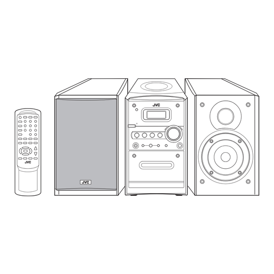
UX-G3, UX-G4
SP-UXG3
CA-UXG3
SP-UXG4
CA-UXG4

TABLE OF CONTENTS

COPYRIGHT © 2005 Victor Company of Japan, Limited
UX-G3
Area suffix
US ------------------------ Singapore
UB ---------------------- Hong Kong
UP ----------------------------- Korea
UT ---------------------------- Taiwan
UW ----------- Brazil,Mexico,Peru
UY ------------------------- Argentina
SP-UXG3
SP-UXG4
UX-G4
Area suffix
A ------------------------ Australia
US ------------------------ Singapore
UB ---------------------- Hong Kong
UT ---------------------------- Taiwan
UW ----------- Brazil,Mexico,Peru
No.MB429
2005/7

Advertisement

Table of Contents
loading

Summary of Contents for JVC SP-UXG3

  • Page 1: Table Of Contents

    UB ---------------------- Hong Kong UT ---------------------------- Taiwan UT ---------------------------- Taiwan UW ----------- Brazil,Mexico,Peru UW ----------- Brazil,Mexico,Peru UY ------------------------- Argentina SP-UXG3 CA-UXG3 SP-UXG3 SP-UXG4 CA-UXG4 SP-UXG4 Lead free solder used in the board (material : Sn-Ag-Cu, melting point : 219 Centigrade) TABLE OF CONTENTS PRECAUTION.
  • Page 2 SPECIFICATION 25 W per channel, min. RMS, driven into 4 Ω at 1 kHz with no more Amplifier Section Output Power than 10% total harmonic distortion (IEC268-3). Audio input sensitivity/Impedance (at 1 kHz) AUX: 500 mV/50 kΩ 4 Ω - 16 Ω Speakers Impedance Tuner FM tuning range...
  • Page 3: Precaution

    SECTION 1 PRECAUTION Safety Precautions (1) This design of this product contains special hardware and voltmeter. many circuits and components specially for safety purpos- Move the resistor connection to each exposed metal es. For continued protection, no changes should be made part, particularly any exposed metal part having a return to the original design unless authorized in writing by the path to the chassis, and measure the AC voltage across...
  • Page 4: Specific Service Instructions

    SECTION 2 SPECIFIC SERVICE INSTRUCTIONS This service manual does not describe SPECIFIC SERVICE INSTRUCTIONS. 1-4 (No.MB429)
  • Page 5: Disassembly

    SECTION 3 DISASSEMBLY Main body 3.1.1 Removing the front panel assembly (See Fig.1 to 6) (1) From the back of the body, remove the two screws A, the two screws B and the two screws D attaching the front pan- CD mechanism assembly el assembly.
  • Page 6 CD mechanism assembly CD mechanism assembly Joint a Front panelh assembly Rear panel assembly Front panel assembly Fig.3 Front panel assembly Rear cover assembly Fig.5 CD mechanism assembly Front panel assembly CN102 Rear panel assembly Fig.4 Main board CN402 Rear cover assembly CON801 Fig.6 1-6 (No.MB429)
  • Page 7 3.1.2 Removing the main board (See Fig.7, 8) • Prior to performing the following procedure, remove the front panel assembly. Front panel assembly CD mechanism assembly (1) Disconnect the wire from all connectors on the main board. (2) Disconnect the wire from the two connectors on the cas- CN103 sette mechanism assembly.
  • Page 8 3.1.3 Removing the CD mechanism assembly (See Fig.9, 10) • Prior to performing the following procedure, remove the front panel assembly and the main board. CD door switch (1) Remove the three bands attaching the wire. Front panel assembly CD mechanism assembly (2) Disconnect the connector from the CD door switch.
  • Page 9 3.1.4 Removing the CD mechanism assembly (See Fig.11 to 13) • Prior to performing the following procedure, remove the front panel assembly, the main board and the CD mechanism as- CD mechanism board sembly. CN601 Caution: wire Before disconnecting the card wire from connector CN601 Cord wire the CD mechanism board and from CD pickup board, solder...
  • Page 10 3.1.5 Removing the CD mechanism (See Fig.14) • Prior to performing the following procedure, remove the front panel assembly, the main board, the CD mechanism assembly and the CD mechanism board. CD mechanism (1) Remove the four screws M attaching the CD mechanism. CD mechanism assembly Fig.14 3.1.6 Removing the headphone board/ AUX board...
  • Page 11 3.1.7 Remove the LCD board (See Fig.16, 17) • Prior to performing the following procedure, remove the front panel assembly, the main board and the CD mechanism as- Front panel assembly sembly. (1) From the front panel, pull out the volume knob and remove the nut and the washer.
  • Page 12 3.1.8 Removing the cassette mechanism assembly (See Fig.18, 19) • Prior to performing the following procedure, remove the front panel assembly and the main board. PUSH OPEN (1) Push 'PUSH OPEN' on the front panel to open the cassette door. (2) Remove the screw R attaching the bracket of the cassette mechanism assembly.
  • Page 13 3.1.9 Removing the heat sink/power board (See Fig.20 to 25) • Prior to performing the following procedure, remove the front panel assembly. Power unit section (1) Remove the four screws Y attaching the holder in the pow- er unit section. (2) Move the power unit section with the wire from the rear cov- er temporarily.
  • Page 14 Holder Heat sink Heat sink e Band e Band Power board Fig.22 Power board Fig.24 Heat sink Power board Heat sink Power board Joint f Holder Band Fig.23 Fig.25 1-14 (No.MB429)
  • Page 15 3.1.10 Removing the power transformer assembly (See Fig.26, 27) • Prior to performing the following procedure, remove the front panel assembly and the power unit section. (1) Remove the four screws F' attaching the power transform- Power trnsfomer assembly er assembly. The bracket comes off at the bottom of the rear cover.
  • Page 16: Adjustment

    Amplifier section • Reference output : Speaker output 0 dB (1 V) / 4 Ω Headphone output -10 dB (0.1 V) / 32 oh CD section • Test disc : CTS-1000 (JVC) TCD-731R (A-BEX) TCD-712R (A-BEX) TCD-785 (A-BEX) 1-16 (No.MB429)
  • Page 17 Cassette amplifier section Item Measuring condition Check and adjustment procedure Standard value Adjusting part 1.Plyback the test tape VT703. Head azimuth Test tape : VT703 Output level : Head azimuth 2.Adjust the head azimuth adjusting screw adjustment Signal output terminal : within +/-2dB adjusting screw so that the phase difference between the...
  • Page 18 Location of adjusting parts Cassette mechanism section CASSETTE MOTOR Tape speed adj. Main board assembly (AM RF) (AM IF) T203 TC201 (AM RF) R245 T204 (AM VT) (114 kHz) T201 (AM OSC) T360 (BIAS FREQUENCY) 1-18 (No.MB429)
  • Page 19: Troubleshooting

    SECTION 5 TROUBLESHOOTING This service manual does not describe TROUBLESHOOTING. (No.MB429)1-19...
  • Page 20: Block Diagram

    Block diagram BACK DISPLAY LIGHT TAPE LOGIC TUNER DECK SOURCE PHONE PHONE SELECTOR AUX IN REMOTE BOARD POWER SPEAKER FOR TUNER FOR TAPE SRAM MAIN POWER RECTIFIER VOLTAGE SUPPLY REGULATOR PICKUP RF AMP CD/MCU FOR MCU VOLTAGE SELECTOR FRO CD REGULATOR DRIVER AC IN...
  • Page 21 Standard schematic diagrams Primary & Power amp section Parts are safety assurance parts. When replacing those parts make sure to use the specified one.
  • Page 22 Main section...
  • Page 23 Display section...
  • Page 24 CD section...
  • Page 25: Printed Circuit Boards

    Printed circuit boards Main board Lead free solder used in the board (material : Sn-Ag-Cu, melting point : 219 Centigrade) (forward side) (reverse side)
  • Page 26 CD board Lead free solder used in the board (material : Sn-Ag-Cu, melting point : 219 Centigrade) (forward side) (reverse side)
  • Page 27 Front board Trans board Lead free solder used in the board (material : Sn-Ag-Cu, melting point : 219 Centigrade) Lead free solder used in the board (material : Sn-Ag-Cu, melting point : 219 Centigrade) (forward side) (forward side) (forward side) (forward side)
  • Page 28: Parts List

    PARTS LIST [ UX-G3 ][ UX-G4 ] * All printed circuit boards and its assemblies are not available as service parts. UX-G3 Area suffix US ---------------------- Singapore UB --------------------- Hong Kong UP ---------------------------- Korea UT --------------------------- Taiwan UW ---------- Brazil,Mexico,Peru UY ----------------------- Argentina UX-G4 Area suffix...
  • Page 29 Exploded view of general assembly and parts list Block No. FM ANT boar US,UB,UT, G3_UY,G4_ UX-G3_UP,UX-G4_A a r d G3_UP F905 G4_A F903 75 94 F902 F901 Power board F904 BKT. board Phone board...
  • Page 30 FM ANT board G3_UP 66 65 US,UB,UT,UW G3_UY,G4_A US,UB,UT UW,G3_UY F905 AC connect board a r d Display board LED board BKT. board CD board AUX board UX-G3_UP UX-G4_A CD board The parts without symbol number are not service.
  • Page 31 General Assembly Block No. [M][1][M][M] Symbol No. Part No. Part Name Description Local  OW688000300014 CD DOOR OW659020003018 METAL PLATE OW399009019023 P.C.MAGNET OW694000300027 STABILIZER RING OW698007953043 STABILIZER CD Pick Up OW698000141034 PUSH OW605000003048 EJECT SPRING OW182010101204 CD DOOR SWITCH DLS-02-1 OW605000300007 CD DOOR SPRING OW689000300051...
  • Page 32  Symbol No. Part No. Part Name Description Local OW618083010038 SCREW M3X10(x4) G3_UP,G4_A G3_UB,G3_US,G3_UT,G3_UW,G3_UY,G4 OW618083010038 SCREW M3X10(x6) _UB,G4_US,G4_UT,G4_UW OW618000012001 SCREW M3X8 HEXAGON(x4) OW618083006023 SCREW M3X6(x7) OW618092608031 SCREW 2.6X8(x12) OW618084012008 SCREW M4X12(x4) OW618093014005 SCREW 3.0X14(x2) OW618083005002 SCREW M3X5 G3_UB,G3_US,G3_UT,G3_UW,G3_UY,G4 OW618092606009 SCREW M2.6X6 _A,G4_UB,G4_US,G4_UT,G4_UW OW622000300025...
  • Page 33: Electrical Parts List

    Electrical parts list Main board  Symbol No. Part No. Part Name Description Local Block No. [0][1] G3_UB, G3_US,  Symbol No. Part No. Part Name Description Local G3_UT,G 3_UW,G Q109 8550 TRANSISTOR OW343008550089 3_UY,G4 IC101 TA2099 OW510002099007 G3_UP _A,G4_U G3_UB, B,G4_US G3_US,...
  • Page 34  Symbol No. Part No. Part Name Description Local  Symbol No. Part No. Part Name Description Local G3_UB,  D403 1N4001 DIODE OW300004001048 G3_US, D404 1N4148 DIODE OW300004148072 G3_UT,G D441 1N4148 DIODE OW300004148072 3_UW,G D442 1N4148 DIODE OW300004148072 Q207 8550 TRANSISTOR OW343008550089...
  • Page 35  Symbol No. Part No. Part Name Description Local  Symbol No. Part No. Part Name Description Local G3_UB, G3_UB, G3_US, G3_US, G3_UT,G G3_UT,G 3_UW,G 3_UW,G C104 OW100180566003 C CAPACITOR 18pF 50V 3_UY,G4 C113 OW120223527006 C CAPACITOR 0.022uF 50V 3_UY,G4 _A,G4_U _A,G4_U B,G4_US...
  • Page 36  Symbol No. Part No. Part Name Description Local  Symbol No. Part No. Part Name Description Local G3_UB, G3_UB, G3_US, G3_US, G3_UT,G G3_UT,G 3_UW,G 3_UW,G C121 OW120331526004 C CAPACITOR 330pF 50V 3_UY,G4 C130 OW131108052912 E CAPACITOR 0.1uF 50V 3_UY,G4 _A,G4_U _A,G4_U B,G4_US...
  • Page 37  Symbol No. Part No. Part Name Description Local  Symbol No. Part No. Part Name Description Local G3_UB, G3_UB, G3_US, G3_US, G3_UT,G G3_UT,G 3_UW,G 3_UW,G C141 OW131222022906 E CAPACITOR 220uF 16V 3_UY,G4 C156 OW120560526008 C CAPACITOR 56pF 50V 3_UY,G4 _A,G4_U _A,G4_U B,G4_US...
  • Page 38  Symbol No. Part No. Part Name Description Local  Symbol No. Part No. Part Name Description Local G3_UB, C242 OW120473527005 C CAPACITOR 0.047uF 50V G3_US, C243 OW131228052903 E CAPACITOR 0.22uF 50V G3_UT,G C244 OW131228052903 E CAPACITOR 0.22uF 50V 3_UW,G C245 OW131101032906 E CAPACITOR...
  • Page 39  Symbol No. Part No. Part Name Description Local  Symbol No. Part No. Part Name Description Local C406 OW131107052916 E CAPACITOR 1uF 50V G3_UB, G3_US, C407 OW120101526004 C CAPACITOR 100pF 50V G3_UT,G C408 OW120101526004 C CAPACITOR 100pF 50V 3_UW,G C410 OW131477052906 E CAPACITOR...
  • Page 40  Symbol No. Part No. Part Name Description Local  Symbol No. Part No. Part Name Description Local G3_UB, G3_UB, G3_US, G3_US, G3_UT,G G3_UT,G 3_UW,G 3_UW,G R107 OW390100326105 C RESISTOR 100KΩ 1/16W 3_UY,G4 R117 OW390270226103 C RESISTOR 27KΩ 1/16W 3_UY,G4 _A,G4_U _A,G4_U B,G4_US...
  • Page 41  Symbol No. Part No. Part Name Description Local  Symbol No. Part No. Part Name Description Local G3_UB, G3_UB, G3_US, G3_US, G3_UT,G G3_UT,G 3_UW,G 3_UW,G R127 OW390220226101 C RESISTOR 22KΩ 1/16W 3_UY,G4 R136 OW390100226108 C RESISTOR 10KΩ 1/16W 3_UY,G4 _A,G4_U _A,G4_U B,G4_US...
  • Page 42  Symbol No. Part No. Part Name Description Local  Symbol No. Part No. Part Name Description Local G3_UB, G3_UB, G3_US, G3_US, G3_UT,G G3_UT,G 3_UW,G 3_UW,G R144 OW390100126102 C RESISTOR 1KΩ 1/16W 3_UY,G4 R152 OW390100126102 C RESISTOR 1KΩ 1/16W 3_UY,G4 _A,G4_U _A,G4_U B,G4_US...
  • Page 43  Symbol No. Part No. Part Name Description Local  Symbol No. Part No. Part Name Description Local G3_UB, G3_UB, G3_US, G3_US, G3_UT,G G3_UT,G 3_UW,G 3_UW,G R162 OW390560126102 C RESISTOR 5.6KΩ 1/16W 3_UY,G4 R204 OW390330126102 C RESISTOR 3.3KΩ 1/16W 3_UY,G4 _A,G4_U _A,G4_U B,G4_US...
  • Page 44  Symbol No. Part No. Part Name Description Local  Symbol No. Part No. Part Name Description Local G3_UB, G3_UB, G3_US, G3_US, G3_UT,G R264 OW390150226101 C RESISTOR 15KΩ 1/16W G3_UT,G 3_UW,G 3_UW,G R238 OW380100123315 C RESISTOR 1KΩ 1/8W 3_UY,G4 3_UY _A,G4_U G4_A,G4 B,G4_US...
  • Page 45  Symbol No. Part No. Part Name Description Local  Symbol No. Part No. Part Name Description Local G3_UB, G3_UB, G3_US, G3_US, G3_UT,G G3_UT,G 3_UW,G 3_UW,G R437 OW390100226108 C RESISTOR 10KΩ 1/16W 3_UY,G4 L101 OW622010001017 SPONGE 10X10X10mm 3_UY,G4 _A,G4_U _A,G4_U B,G4_US B,G4_US ,G4_UT,...
  • Page 46  Symbol No. Part No. Part Name Description Local  Symbol No. Part No. Part Name Description Local L901 OW155000400015 CHOKE COIL 12.7X7.5X5 G3_UP CONNECTOR 9P for CASS CN202 OW261041092246 WIRE MECH T101 OW140000332028 810017 10mm YEL G3_UP CN203 OW260011070025 HEADER T101 OW118100070053...
  • Page 47  Symbol No. Part No. Part Name Description Local  Symbol No. Part No. Part Name Description Local G4_A,G4 TIEE11 OW235050040011 WIRE 40mm BLK G3_UP _UB,G4_ TIEIE1 OW235050040011 WIRE 40mm BLK J135 OW390000049305 C RESISTOR 0Ω 1/8W US,G4_U G3_UB, T,G4_U G3_US, G3_UT,G G3_UB,...
  • Page 48: Power Board

     Symbol No. Part No. Part Name Description Local  Symbol No. Part No. Part Name Description Local G3_UB,  Z441 6.2V0.5W Z DIODE OW303050062074 G3_UP,G  Z481 6.2V0.5W Z DIODE OW303050062074 3_UP,G3 _US,G3_ UT,G3_U W,G3_U Power board Y,G4_A, XXXXX OW169004344028 FERRITE CORE For phone...
  • Page 49: Display Board

    Display board  Symbol No. Part No. Part Name Description Local Block No. [0][3] R818 OW380100123315 C RESISTOR 1KΩ 1/8W R819 OW380220223314 C RESISTOR 22KΩ 1/8W  Symbol No. Part No. Part Name Description Local R820 OW380100123315 C RESISTOR 1KΩ 1/8W ...
  • Page 50  Symbol No. Part No. Part Name Description Local  Symbol No. Part No. Part Name Description Local R740 OW390100126102 C RESISTOR 1KΩ 1/16W Evqjae 05R SW702 OW182010101194 TACT SWITCH H=5mm R741 OW390270126106 C RESISTOR 2.7KΩ 1/16W Evqjae 05R R742 OW390100226108 C RESISTOR 10KΩ...
  • Page 51  Symbol No. Part No. Part Name Description Local  Symbol No. Part No. Part Name Description Local C632 OW120153527006 C CAPACITOR 0.015uF 50V R618 OW390150326107 C RESISTOR 150KΩ 1/16W C633 OW131472012907 E CAPACITOR 470uF 10V R619 OW390150326107 C RESISTOR 150KΩ...
  • Page 52  Symbol No. Part No. Part Name Description Local R6102 OW390220026107 C RESISTOR 220Ω 1/16W R6103 OW390220026107 C RESISTOR 220Ω 1/16W R6110 OW390100326105 C RESISTOR 100KΩ 1/16W R6111 OW390100326105 C RESISTOR 100KΩ 1/16W R6171 OW390000029121 C RESISTOR 0Ω 1/16W R6181 OW390000029121 C RESISTOR 0Ω...
  • Page 53: Packing Materials And Accessories Parts List

    Packing materials and accessories parts list Block No. No additional / supplemental order of WARRANTY CARDs are available. (UX-G3_UP) A1 A7 A1 A9 (UB) US,UB,UT,UW UX-G3_UP UX-G3_UY UX-G4_A (US,UT,UW) The parts without symbol number are not service. 3-26...
  • Page 54 Packing and Accessories Block No. [M][3][M][M] Symbol No. Part No. Part Name Description Local  OW904020003248 INST BOOK KOR LVT1364-007A G3_UP OW904020003226 INST BOOK SPA LVT1364-010A G3_UY OW903020004045 INST BOOK ENG LVT1364-011A G4_A OW904020003194 INST BOOK ENG CHI(PEKIN) LVT1364-012A G3_UB,G4_UB OW904020003204 INST BOOK ENG CHI(PEKIN) LVT1364-006B...

This manual is also suitable for:

Ca-uxg3Ca-uxg4Sp-uxg4Ux-g3Ux-g4

Table of Contents