Table of Contents
Advertisement
Quick Links
Advertisement
Table of Contents

Subscribe to Our Youtube Channel
Related Manuals for Asus Z170-WS


Summary of Contents for Asus Z170-WS
- Page 1 Z170-WS...
- Page 2 Product warranty or service will not be extended if: (1) the product is repaired, modified or altered, unless such repair, modification of alteration is authorized in writing by ASUS; or (2) the serial number of the product is defaced or missing.
-
Page 3: Table Of Contents
Contents Safety information ..................... vii About this guide ....................... viii Z170-WS specifications summary ................x Package contents ..................... xvi Installation tools and components ................ xvii Chapter 1: Product Introduction Special features..................1-1 1.1.1 Product highlights................ 1-1 1.1.2 ASUS-exclusive workstation features ......... 1-2 1.1.3... - Page 4 3.6.11 Intel(R) Thunderbolt Configuration ..........3-45 Monitor menu ................... 3-46 Boot menu ....................3-52 Tool menu ....................3-57 3.9.1 ASUS EZ Flash 3 Utility ............3-57 3.9.2 Secure Erase ................3-57 3.9.3 ASUS Overclocking Profile ............3-59 3.9.4 ASUS SPD Information ............. 3-60 3.9.5...
- Page 5 Contents Chapter 4: Software Support Installing an operating system ..............4-1 4.1.1 Windows 7 and USB 3.0 driver for 100 Series ......4-1 ® Support DVD information ................4-8 4.2.1 Running the support DVD ............4-8 4.2.2 Obtaining the software manuals..........4-9 Software information ................
- Page 6 Installing three SLI-ready graphics cards ........6-8 6.2.4 Installing four SLI-ready graphics cards ........6-9 6.2.5 Installing the device drivers ............6-10 6.2.6 Enabling the NVIDIA technology ........6-10 ® ® Appendices Z170-WS block diagram ..................A-1 Notices ........................A-2 ASUS contact information ..................A-6...
-
Page 7: Safety Information
Safety information Electrical safety • To prevent electrical shock hazard, disconnect the power cable from the electrical outlet before relocating the system. • When adding or removing devices to or from the system, ensure that the power cables for the devices are unplugged before the signal cables are connected. If possible, disconnect all power cables from the existing system before you add a device. -
Page 8: About This Guide
Refer to the following sources for additional information and for product and software updates. ASUS website The ASUS website (www.asus.com) provides updated information on ASUS hardware and software products. Optional documentation Your product package may include optional documentation, such as warranty flyers, that may have been added by your dealer. -
Page 9: Conventions Used In This Guide
Conventions used in this guide To ensure that you perform certain tasks properly, take note of the following symbols used throughout this manual. DANGER/WARNING: Information to prevent injury to yourself when trying to complete a task. CAUTION: Information to prevent damage to the components when trying to complete a task. -
Page 10: Z170-Ws Specifications Summary
Z170-WS specifications summary LGA1151 socket for 6th Generation Intel Core™ i7/ i5/ i3/Pentium ® ® Celeron Processors ® Supports 14nm CPU Supports Intel Turbo Boost Technology 2.0* ® * The Intel Turbo Boost Technology 2.0 support depends on the CPU types. - Page 11 Z170-WS specifications summary Storage Intel Z170 Express Chipset with RAID 0, 1, 5, 10 and Intel ® Rapid Storage Technology 14 support* - 2 x M.2 Socket 3 with M Key, type 2242/2260/2280/22110 storage devices support (both SATA & PCIE mode)** - 6 x SATA 6.0 Gb/s ports (gray)
- Page 12 - 1 x USB 3.1/3.0/2.0 port @back panel (Type C) ASUS Exclusive Superb Performance Features OC Design: ASUS PRO Clock Technology - Full BCLK range for extreme overclocking performance. 5-Way Optimization - Whole system optimization with a single click! Perfectly consolidates better CPU performance, power saving, digital power control, system cooling and app usages.
- Page 13 128 Mb Flash ROM, UEFI AMI BIOS, PnP, DMI3.0, WfM2.0, SM BIOS features BIOS 3.0, ACPI 5.0, Multi-language BIOS, ASUS EZ Flash 3, CrashFree BIOS 3, F11 EZ Tuning Wizard, F6 Qfan Control, F3 My Favorites, Quick Note, Last Modified log, F12 PrintScreen and...
- Page 14 4 x Chassis Fan connectors (4-pin) for both 3-pin(DC mode) and 4-pin(PWM mode) coolers control 1 x Front panel audio connector (AAFP) 1 x S/PDIF out header 1 x Thunderbolt header (5-pin) for ASUS ThunderboltEX series support 1 x TPM connector 1 x 24-pin EATX Power connector...
- Page 15 Z170-WS specifications summary WfM 2.0, DMI 3.0, WOL by PME, PXE Manageability Drivers Support DVD contents ASUS Utilities EZ Update Anti-virus software (OEM version) Windows Operating system ® support Windows 8.1* ® Windows ® *64-bit supported only ATX Form Factor, 12” x 9.6” (30.5 cm x 24.4 cm) Form factor Specifications are subject to change without notice.
-
Page 16: Package Contents
Support DVD 6 x Serial ATA 6.0 Gb/s cables COM port bracket 1 x ASUS SLI bridge connector 1 x ASUS 4-Way SLI bridge connector 1 x ASUS 3-Way SLI bridge 1 x 2-in-1 Q-connector connector 1 x Q-Shield 2 x M.2 Screw package... -
Page 17: Installation Tools And Components
Installation tools and components Intel LGA1151 CPU ® Intel LGA1151 compatible CPU Fan ® Phillips (cross) screwdriver SATA hard disk drive PC chassis DIMM 1 bag of screws Power supply unit SATA optical disc drive (optional) Graphics card The tools and components in the table above are not included in the motherboard package. xvii... - Page 18 xviii...
-
Page 19: Chapter 1: Product Introduction
This motherboard has the latest USB 3.1 connectivity built in for the very fastest USB data transfers — that’s up to 10 Gb/s, or twice as fast as USB 3.0. The next-generation standard is completely backward-compatible with your existing USB devices, and you’ll be all set for USB 3.1’s breakneck speeds. ASUS Z170-WS... -
Page 20: Asus-Exclusive Workstation Features
If a workstation is behaving abnormally, plug a flash drive into the adjacent USB port, press the motherboard’s dedicated Flash Log button and all ASUS Q-Code event logs for the current live session will be copied to the drive. -
Page 21: Motherboard Overview
Before you install or remove any component, ensure that the ATX power supply is switched off or the power cord is detached from the power supply. Failure to do so may cause severe damage to the motherboard, peripherals, or components. ASUS Z170-WS... -
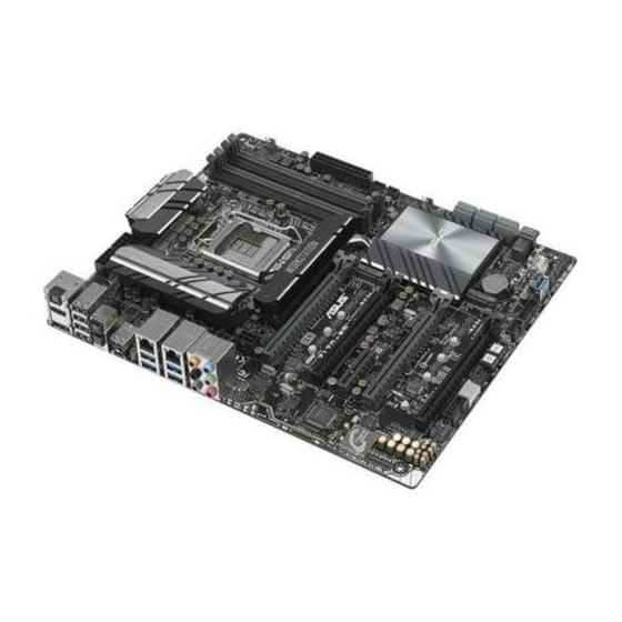
Page 22: Motherboard Layout
1.2.2 Motherboard layout Refer to 1.2.9 Internal connectors and 2.3.1 Rear I/O connection for more information about rear panel connectors and internal connectors. Chapter 1: Product Introduction... -
Page 23: Layout Contents
23. Q-Code LEDs 1-20 24. Serial port connector (10-1 pin COM1) 1-36 25. Front panel audio connector (10-1 pin AAFP) 1-26 26. Digital audio connector (4-1 pin SPDIF_OUT) 1-26 27. M.2 Socket 3 1-35 28. Thunderbolt header (5-pin TB_HEADER) 1-34 ASUS Z170-WS... -
Page 24: Central Processing Unit (Cpu)
Contact your retailer immediately if the PnP cap is missing, or if you see any damage to the PnP cap/socket contacts/motherboard components. ASUS will shoulder the cost of repair only if the damage is shipment/ transit-related. -
Page 25: System Memory
The motherboard comes with four DDR 4 (Double Data Rate 4) Dual Inline Memory Modules (DIMM) slots. A DDR4 module is notched differently from a DDR, DDR2 or DDR3 module. DO NOT install a DDR, DDR2 or DDR3 memory module to the DDR4 slot. Recommended memory configurations ASUS Z170-WS... -
Page 26: Memory Configurations
(D/C) from the same vendor. Check with the vendor to get the correct memory modules. • Visit the ASUS website for the latest QVL. Chapter 1: Product Introduction... -
Page 27: Expansion Slots
Unplug the power cord before adding or removing expansion cards. Failure to do so may cause you physical injury and damage motherboard components. Slot No. Slot Description PCIe 3.0/2.0 x16_1 slot PCIe 3.0/2.0 x16_2 slot PCIe 2.0 x4_1 slot PCIe 3.0/2.0x16_3 slot PCIe 3.0/2.0 x16_4 slot ASUS Z170-WS... - Page 28 PCI Express 3.0 operating mode Slot 3-WAY SLI 4-WAY SLI Single VGA SLI CrossFireX CrossFireX CrossFireX (single VGA recommended) (dual VGA recommended) • We recommend that you provide sufficient power when running CrossFireX™ or SLI ® mode. • Connect a chassis fan to the motherboard connector labeled CHA_FAN1-4 when using multiple graphics cards for better thermal environment.
- Page 29 PCIe x16_1 shared PCIe x16_2 shared PCIe x16_3 shared PCIe x16_4 shared PCIe x4_1 shared SMBUS Controller shared Intel SATA Controller shared Intel LAN1(i219) shared Intel LAN2(I210) shared Intel xHCI shared HD Audio shared ASMedia 1142_1 shared ASUS Z170-WS 1-11...
-
Page 30: Onboard Buttons And Switches
1.2.6 Onboard buttons and switches Onboard buttons and switches allow you to fine-tune performance when working on a bare or open-case system. This is ideal for overclockers and gamers who continually change settings to enhance system performance. Power-on button The motherboard comes with a power-on button that allows you to power up or wake up the system. - Page 31 BIOS default settings. A message will appear during POST reminding you that the BIOS has been restored to its default settings. • We recommend that you download and update to the latest BIOS version from www.asus.com after using the MemOK! function. ASUS Z170-WS 1-13...
- Page 32 TPU switch With its two-level adjustment functions, the TPU allows you to automatically adjusts the CPU ratio and clock speed for an optimal system performance. • Enable this switch when the system is powered off. • When the TPU switch is set to Enabled (TPU_I: CPU Ratio Boost), the system automatically adjusts the CPU ratio for an enhanced performance.
- Page 33 • You may change the EPU settings in the software application or BIOS setup program and enable the EPU function at the same time. However, the system will use the last setting you have made. ASUS Z170-WS 1-15...
- Page 34 Clear CMOS button (CLR_CMOS) Press this button to clear the BIOS setup information only when the systems hangs due to overclocking. EZ XMP switch Enable this switch to overclock the installed DIMMs, allowing you to enhance the DIMM’s speed and performance. Chapter 1: Product Introduction 1-16...
-
Page 35: Jumpers
Chassis Fan control setting (3-pin CHAFAN_SEL) This jumpers allow you to switch fan pin selection. The CHAFAN_SEL jumper is for the front fans and rear fans control. Set pins 1-2 when using 3-pin fans or pins 2-3 when using 4-pin fans. ASUS Z170-WS 1-17... -
Page 36: Onboard Leds
1.2.8 Onboard LEDs POST State LEDs The POST State LEDs provide the status of these key components during POST (Power-On-Self Test): CPU, memory modules, VGA card, and hard disk drives. If an error is found, the critical component’s LED stays lit up until the problem is solved. TPU LED (TPU_LED) The TPU LED lights up when the TPU switch is enabled. - Page 37 EPU LED (OLED2) The EPU LED lights up when the EPU switch is enabled. EZ XMP LED (XLED1) This LED lights up when you enable the EZ XMP switch. ASUS Z170-WS 1-19...
- Page 38 Q-Code LEDs The Q-Code LED design provides you with a 2-digit error code that displays the system status. Refer to the Q-Code table on the next page for details. Chapter 1: Product Introduction 1-20...
- Page 39 S3 Resume is stared (S3 Resume PPI is called by the DXE IPL) S3 Boot Script execution Video repost OS S3 wake vector call E4 – E7 Reserved for future AMI progress codes S3 Resume Failed (continued on the next page) ASUS Z170-WS 1-21...
- Page 40 Code Description S3 Resume PPI not Found S3 Resume Boot Script Error S3 OS Wake Error EC – EF Reserved for future AMI error codes Recovery condition triggered by firmware (Auto recovery) Recovery condition triggered by user (Forced recovery) Recovery process started Recovery firmware image is found Recovery firmware image is loaded Reserved for future AMI progress codes...
- Page 41 No Console Output Devices are found No Console Input Devices are found Invalid password Error loading Boot Option (LoadImage returned error) Boot Option is failed (StartImage returned error) Flash update is failed Reset protocol is not available ASUS Z170-WS 1-23...
- Page 42 ACPI/ASL Checkpoints (under OS) Code Description System is entering S3 sleep state System is entering S4 sleep state System is entering S5 sleep state System is waking up from the S3 sleep state System is waking up from the S4 sleep state System has transitioned into ACPI mode.
-
Page 43: Internal Connectors
SATA mode. When you use both connectors, the system automatically detects the devices connected to these connectors and set a higher priority to M.2 Socket 3 than SATA interface. You can adjust the BIOS settings to set the priority. ASUS Z170-WS 1-25... - Page 44 U.2 connector (U.2) This motherboard comes with a U.2 connector which supports PCIe 3.0 x4 NVM Express storage. Digital audio connector (4-1 pin SPDIF_OUT) This connector is for an additional Sony/Philips Digital Interface (S/PDIF) port. Connect the S/PDIF Out module cable to this connector, then install the module to a slot opening at the back of the system chassis.
- Page 45 Front Panel Type item in the BIOS setup to [HD Audio] or [AC97]. T_Sensor connector (2-pin T_SENSOR1) This connector is for the thermistor cable that allows you to monitor the temperature of your motherboard’s critical components and connected devices. ASUS Z170-WS 1-27...
- Page 46 Chassis intrusion connector (4-1 pin CHASSIS) This connector is for a chassis-mounted intrusion detection sensor or switch. Connect one end of the chassis intrusion sensor or switch cable to this connector. The chassis intrusion sensor or switch sends a high-level signal to this connector when a chassis component is removed or replaced.
- Page 47 USB 3.0 ports under Windows ® • The plugged USB 3.0 device may run on xHCI or EHCI mode depending on the operating system’s setting. • These USB 3.0 ports only support Turbo Mode when using USB 3.0 Boost feature. ASUS Z170-WS 1-29...
- Page 48 DO NOT connect a 1394 cable to the USB connectors. Doing so will damage the motherboard! You can connect the front panel USB cable to the ASUS Q-Connector (USB) first, and then install the Q-Connector (USB) to the USB connector onboard if your chassis supports front panel USB ports.
- Page 49 Ensure that the CPU fan cable is securely installed to the CPU fan connector. • The CPU_FAN connector supports the CPU fan of maximum 1A (12 W) fan power. • The CPU_FAN connector and CHA_FAN connectors support the ASUS FAN Xpert 3 feature. • W_PUMP function support depends on water cooling device.
- Page 50 ATX power connectors (24-pin EATXPWR; 8-pin EATX12V1, 8-pin EATX12V, 6-pin EATX12V_1) These connectors are for ATX power supply plugs. The power supply plugs are designed to fit these connectors in only one orientation. Find the proper orientation and push down firmly until the connectors completely fit. •...
-
Page 51: System Panel Connector
Pressing the power switch for more than four seconds while the system is ON turns the system OFF. • Reset button (2-pin RESET) This 2-pin connector is for the chassis-mounted reset button for system reboot without turning off the system power. ASUS Z170-WS 1-33... - Page 52 DirectKey connector (2-pin DRCT) This connector is for the chassis-mounted button that supports the DirectKey function. Connect the button cable that supports DirectKey, from the chassis to this connector on the motherboard. Ensure that your chassis comes with the extra button cable that supports the DirectKey feature.
- Page 53 M.2 Socket 3 than U.2 interface. You can adjust the BIOS settings to set the priority. • When using Intel Desktop Responsiveness technologies with PCIe M.2 device, ® ensure to set up the Windows UEFI operating system under RAID mode. ® The M.2 (NGFF) SSD module is purchased separately. ASUS Z170-WS 1-35...
- Page 54 Serial port connector (10-1 pin COM1) This connector is for a serial (COM) port. Connect the serial port module cable to this connector, then install the module to a slot opening at the back of the system chassis. The COM module is purchased separately. Chapter 1: Product Introduction 1-36...
-
Page 55: Chapter 2: Basic Installation
2.1.1 Motherboard installation Install the ASUS Q-Shield to the chassis rear I/O panel. Place the motherboard into the chassis, ensuring that its rear I/O ports are aligned to the chassis’ rear I/O panel. - Page 56 Place nine screws into the holes indicated by circles to secure the motherboard to the chassis. DO NOT overtighten the screws! Doing so can damage the motherboard. Chapter 2: Basic Installation...
-
Page 57: Cpu Installation
CPU installation Ensure that you install the correct CPU designed for LGA1151 socket only. DO NOT install a CPU designed for LGA1155 and LGA1156 sockets on the LGA1151 socket. Top of CPU Bottom of CPU Bottom of CPU ASUS Z170-WS... - Page 58 Top of CPU • The CPU Installation Tool is only compatible on ASUS motherboards with a Intel ® LGA1151 socket. • Ensure that the CPU is firmly clicked into place before installing it onto the CPU socket on the motherboard. • Use the CPU Installation Tool for installing the CPU only. DO NOT damage or bend the CPU Installation Tool. • Always firmly hold both sides of the CPU Installation Tool when installing, removing, or picking up the CPU Installation Tool. • Ensure to use a soft stable surface when installing the CPU to the CPU Installation Tool to prevent CPU damage. • ASUS will not cover damages resulting from incorrect CPU installation/removal, incorrect CPU orientation/placement, or other damages resulting from negligence by the user.
-
Page 59: Cpu Heatsink And Fan Assembly Installation
2.1.3 CPU heatsink and fan assembly installation Apply the Thermal Interface Material to the CPU heatsink and CPU before you install the heatsink and fan, if necessary. To install the CPU heatsink and fan assembly ASUS Z170-WS... - Page 60 To uninstall the CPU heatsink and fan assembly Chapter 2: Basic Installation...
-
Page 61: Dimm Installation
2.1.4 DIMM installation To remove a DIMM ASUS Z170-WS... -
Page 62: Atx Power Connection
2.1.5 ATX Power connection Chapter 2: Basic Installation... -
Page 63: Sata Device Connection
2.1.6 SATA device connection ASUS Z170-WS... -
Page 64: Front I/O Connector
2.1.7 Front I/O connector To install ASUS Q-Connector To install USB 2.0 connector To install front panel audio connector AAFP USB 2.0 To install USB 3.0 connector USB 3.0 Chapter 2: Basic Installation 2-10... -
Page 65: Expansion Card Installation
2.1.8 Expansion Card installation To install PCIe x16 cards To install PCIe x1 cards ASUS Z170-WS 2-11... -
Page 66: Bios Update Utility
BIOS update utility USB BIOS Flashback USB BIOS Flashback allows you to easily update the BIOS without entering the existing BIOS or operating system. Simply insert a USB storage device to the USB port (the USB port hole marked in white on the I/O shield) then press the USB BIOS Flashback button for three seconds to automatically update the BIOS. - Page 67 • Updating BIOS may have risks. If the BIOS program is damaged during the process and results to the system’s failure to boot up, please contact your local ASUS Service Center. Q-Code Logger Q-Code Logger allows you to easily check Q-Code event logs with opening the computer’s case.
-
Page 68: Motherboard Rear And Audio Connections
Motherboard rear and audio connections 2.3.1 Rear I/O connection Rear panel connectors Optical S/PDIF Out port DisplayPort USB 2.0 ports 7-10 (upper port USB BIOS Flashback button supports Key Express) Q-Code Logger button USB 3.1 Type-C port EC1 (supports USB 3.1 Boost) USB 3.1 Type-A port EA2 (supports USB 3.0 ports 3 and 4 USB 3.1 Boost) - Page 69 S5 mode You can disable the LAN controllers in BIOS. Once disabled, the LAN2 port’s ACT/LINK LED and SPEED LED stop blinking. For LAN1 port, the ACT/LINK LED still blinks even if you disabled it. ASUS Z170-WS 2-15...
-
Page 70: Audio I/O Connections
** Audio 2, 4, 6, or 8-channel configuration Port Headset 4-channel 6-channel 8-channel 2-channel Line In Light Blue Line In Line In Line In Lime Line Out Front Speaker Out Front Speaker Out Front Speaker Out Mic In Pink Mic In Mic In Mic In Center/Subwoofer... - Page 71 Connect to 2.1 channel Speakers Connect to 4.1 channel Speakers Connect to 5.1 channel Speakers If you are using Windows 8.1 platform, use only the gray audio port for Side Speaker Out in a 6-channel configuration. ASUS Z170-WS 2-17...
-
Page 72: Starting Up For The First Time
Connect to 7.1 channel Speakers When the DTS UltraPC II function is enabled, ensure to connect the rear speaker to the gray port. Starting up for the first time After making all the connections, replace the system case cover. Ensure that all switches are off. Connect the power cord to the power connector at the back of the system chassis. -
Page 73: Turning Off The Computer
While the system is ON, press the power button for less than four seconds to put the system on sleep mode or soft-off mode, depending on the BIOS setting. Press the power switch for more than four seconds to let the system enter the soft-off mode regardless of the BIOS setting. ASUS Z170-WS 2-19... - Page 74 Chapter 2: Basic Installation 2-20...
-
Page 75: Chapter 3: Bios Setup
BIOS Setup Knowing BIOS The new ASUS UEFI BIOS is a Unified Extensible Interface that complies with UEFI architecture, offering a user-friendly interface that goes beyond the traditional keyboard- only BIOS controls to enable a more flexible and convenient mouse input. You can easily navigate the new UEFI BIOS with the same smoothness as your operating system. -
Page 76: Bios Setup Program
BIOS setup program Use the BIOS Setup to update the BIOS or configure its parameters. The BIOS screen include navigation keys and brief onscreen help to guide you in using the BIOS Setup program. Entering BIOS at startup To enter BIOS Setup at startup, press <Delete> during the Power-On Self Test (POST). If you do not press <Delete>, POST continues with its routines. -
Page 77: Ez Mode
Click to go to Advanced mode Loads optimized Search on the FAQ default settings Click to display boot devices Selects the boot device priority The boot device options vary depending on the devices you installed to the system. ASUS Z170-WS... -
Page 78: Advanced Mode
3.2.2 Advanced Mode The Advanced Mode provides advanced options for experienced end-users to configure the BIOS settings. The figure below shows an example of the Advanced Mode. Refer to the following sections for the detailed configurations. To switch from EZ Mode to Advanced Mode, click Advanced Mode(F7) or press the <F7> hotkey. -
Page 79: Menu Bar
This button above the menu bar allows you to view and tweak the overclocking settings of your system. It also allows you to change the motherboard’s SATA mode from AHCI to RAID mode. Refer to section 3.2.4 EZ Tuning Wizard for more information. ASUS Z170-WS... -
Page 80: Hot Keys
Move your mouse over this button to show a QR code, scan this QR code on your mobile device to connect to the BIOS FAQ web page of the ASUS support website. You can also scan the following QR code:... -
Page 81: Qfan Control
Click to activate DC Mode configured PWM Mode Select a profile to apply to Click to apply the fan setting your fans Click to undo the Click to go back to main menu changes Select to manually configure your fans ASUS Z170-WS... - Page 82 Configuring fans manually Select Manual from the list of profiles to manually configure your fans’ operating speed. Speed points Select to manually configure your fans To configure your fans: Select the fan that you want to configure and to view its current status. Click and drag the speed points to adjust the fans’...
-
Page 83: Ez Tuning Wizard
To start OC Tuning: Press <F11> on your keyboard or click from the BIOS screen to open EZ Tuning Wizard screen. Click OC then click Next. Select a PC scenario Daily Computing or Gaming/Media Editing, then click Next. ASUS Z170-WS... -
Page 84: Creating Raid
Select a Main Cooling System BOX cooler, Tower cooler, Water cooler, or I’m not sure, then click Next. After selecting the Main Cooling System, click Next then click Yes to start the OC Tuning. Creating RAID To create RAID: Press <F11> on your keyboard or click from the BIOS screen to open EZ Tuning Wizard screen. - Page 85 Speed (RAID5). After selecting the type of RAID, click Next then click Yes to continue the RAID setup. After the RAID setup is done, click Yes to exit the setup then click OK to reset your system. ASUS Z170-WS 3-11...
-
Page 86: My Favorites
My Favorites My Favorites is your personal space where you can easily save and access your favorite BIOS items. My Favorites comes with several performance, power saving, and fast boot related items by default. You can personalize this screen by adding or removing items. Chapter 3: BIOS Setup 3-12... - Page 87 User-managed items such as language and boot order • Configuration items such as Memory SPD Information, system time and date. Click Exit (ESC) or press <Esc> key to close Setup Tree Map screen. Go to My Favorites menu to view the saved BIOS items. ASUS Z170-WS 3-13...
-
Page 88: Main Menu
Main menu The Main menu screen appears when you enter the Advanced Mode of the BIOS Setup program. The Main menu provides you an overview of the basic system information, and allows you to set the system date, time, language, and security settings. Security The Security menu items allow you to change the system security settings. -
Page 89: Administrator Password
To clear the user password, follow the same steps as in changing a user password, but press <Enter> when prompted to create/confirm the password. After you clear the password, the User Password item on top of the screen shows [Not Installed]. ASUS Z170-WS 3-15... -
Page 90: Ai Tweaker Menu
Ai Tweaker menu The Ai Tweaker menu items allow you to configure overclocking-related items. Be cautious when changing the settings of the Ai Tweaker menu items. Incorrect field values can cause the system to malfunction. The configuration options for this section vary depending on the CPU and DIMM model you installed on the motherboard. - Page 91 CPU permanently. ASUS MultiCore Enhancement [Auto] [Auto] This item allows you to maximize the oveclocking performance optimized by ASUS core ratio settings. [Disabled] This item allows you to set to default core ratio settings. CPU Core Ratio [Auto] This item allows you to set the CPU core ratio limit per core or synchronize automatically to all cores.
- Page 92 Applies water cooling overclocking conditions. Ensure to use water cooling device before selecting [TPU II]. EPU Power Saving Mode [Disabled] The ASUS EPU (Energy Processing Unit) sets the CPU in its minimum power consumption settings. Configuration options: [Disabled] [Enabled] CPU SVID Support Disable this item to stop the CPU from communicating with the external voltage regulator.
-
Page 93: Dram Timing Control
DRAM WRITE to READ Delay [Auto] Configuration options: [Auto] [1] – [15] DRAM WRITE to READ Delay L [Auto] Configuration options: [Auto] [1] – [15] DRAM WRITE to READ Delay S [Auto] Configuration options: [Auto] [1] – [15] ASUS Z170-WS 3-19... - Page 94 DRAM CKE Minimum Pulse Width [Auto] Configuration options: [Auto] [1] – [15] DRAM Write Latency [Auto] Configuration options: [Auto] [1] – [31] Skew Control ODT RTT WR (CHA) [Auto] Configuration options: [Auto] [0 DRAM CLOCK] [80 DRAM CLOCK] [120 DRAM CLOCK] [240 DRAM CLOCK] [255 DRAM CLOCK] ODT RTT PARK (CHA) [Auto] Configuration options: [Auto] [0 DRAM CLOCK] [34 DRAM CLOCK] [40 DRAM CLOCK] [48 DRAM CLOCK] [60 DRAM CLOCK] [80 DRAM...
- Page 95 Configuration options: [Auto] [0] - [15] DRAM IOL (CHA DIMM1 Rank1) [Auto] Configuration options: [Auto] [0] - [15] DRAM IOL (CHB DIMM0 Rank0) [Auto] Configuration options: [Auto] [0] - [15] DRAM IOL (CHB DIMM0 Rank1) [Auto] Configuration options: [Auto] [0] - [15] ASUS Z170-WS 3-21...
- Page 96 DRAM IOL (CHB DIMM1 Rank0) [Auto] Configuration options: [Auto] [0] - [15] DRAM IOL (CHB DIMM1 Rank1) [Auto] Configuration options: [Auto] [0] - [15] IO Latency offset CHA IO_Latency_offset Configuration options: [Auto] [0] - [127] CHB IO_Latency_offset Configuration options: [Auto] [0] - [127] IO Latency RFR delay CHA RFR delay Configuration options: [Auto] [0] - [127]...
- Page 97 [Disable Both DIMMS] MCH Full Check [Auto] Enable this item to enhance the stability of your system. Disable this item to enhance the DRAM overclocking capability. Configuration options: [Auto] [Enabled] [Disabled] DLLBwEn [Auto] Configuration options: [Auto] [1] - [7] ASUS Z170-WS 3-23...
- Page 98 External DIGI+ Power Control CPU Load-line Calibration [Auto] Load-line is defined by Intel specification and affects CPU power voltage. The CPU ® working voltage decreases proportionally to CPU loading. Higher load-line calibration could get higher voltage and good overclocking performance, but increases the CPU and VRM thermal conditions.
- Page 99 Configure higher values when overclocking or under a high CPU loading for extra power support. DRAM Power Phase Control [Extreme] This item allows you to set the power phase control of the DRAM. Configuration options: [Optimized] [Extreme] ASUS Z170-WS 3-25...
- Page 100 DRAM Switching Frequency [Auto] This item affects the VRM transient response speed and the component thermal production. Select [Manual] to configure a higher frequency for a quicker transient response speed. Configuration options: [Auto] [Manual] DO NOT remove the thermal module. The thermal conditions should be monitored. The following item appears only when you set the CPU VRM Switching Frequency to [Manual].
- Page 101 This item allows you to set the magnitude of the base clock driven for the processor. Configuration options: [Auto] [700mV] [800mV] [900mV] [1000mV] BCLK Slew Rate [Auto] This item allows you to set the speed at which each clock rises and falls. Configuration options: [Auto] [1.5V/ns] [2.5V/ns] [3.5V/ns] [4.5V/ns] ASUS Z170-WS 3-27...
- Page 102 BCLK Spread Spectrum [Auto] This item allows you to reduce the EMI. Diable to get more accurate base clocks. Configuration options: [Auto] [Disabled] [-0.22] [-0.34] [-0.46] [+0.12] [+0.22] [+0.28] [+0.38] [+0.17] BCLK Frequency Slew Rate [Auto] Configuration options: [Auto] [Disabled] [32us/MHz] [64us/MHz] [128us/MHz] [512us/ MHz] DRAM VTT Voltage [Auto] Configuration options: [Auto] [0.500] - [1.300]...
- Page 103 Configuration options: [Auto] [1.0000] - [2.0000] CPU VCCIO Voltage [Auto] Configuration options: [Auto] [0.70000] - [1.80000] CPU System Agent Voltage [Auto] Configuration options: [Auto] [0.70000] - [1.80000] PLL Termination Voltage [Auto] Configuration options: [Auto] [0.36000] - [2.10000] ASUS Z170-WS 3-29...
- Page 104 PCH Core Voltage [Auto] Configuration options: [Auto] [0.70000] - [1.80000] CPU Standby Voltage [Auto] Configuration options: [Auto] [0.80000] - [1.80000] DRAM REF Voltage Control DRAM CTRL REF Voltage on CHA/CHB [Auto] Configures the DRAM reference voltage on the control lines. The reference volage will be the DRAM voltage times the configured value.
-
Page 105: Advanced Menu
The Advanced menu items allow you to change the settings for the CPU and other system devices. Be cautious when changing the settings of the Advanced menu items. Incorrect field values can cause the system to malfunction. ASUS Z170-WS 3-31... -
Page 106: Cpu Configuration
3.6.1 CPU Configuration The items in this menu show the CPU-related information that the BIOS automatically detects. The items in this menu may vary based on the CPU installed. Hyper-threading [Enabled] This item allows a hyper-threading processor to appear as two logical processors, allowing the operating system to schedule two threads or processors simultaneously. - Page 107 When enabled, CPU will switch to minimum speed when all cores enter C-State. Configuration options: [Enabled] [Disabled] CPU C3 Report [Enabled] This item allows you to disable or enable the CPU C3 report to the operating system. Configuration options: [Enabled] [Disabled] ASUS Z170-WS 3-33...
-
Page 108: Platform Misc Configuration
CPU C6 Report [Enabled] This item allows you to disable or enable the CPU C6 report to the operating system. Configuration options: [Enabled] [Disabled] CPU C7 Report [CPU C7s] This item allows you to disable or enable the CPU C7 report to the operating system. - Page 109 ASPM to take effect. Configuration options: [Disabled] [L1] PEG ASPM Support [Disabled] This item allows you to select the ASPM state for energy-saving conditions, or use the ASUS optimized energy saving profile. Configuration options: [Disabled] [Auto] [ASPM L0s] [ASPM L1] [ASPM L0sL1]...
-
Page 110: System Agent (Sa) Configuration
3.6.3 System Agent (SA) Configuration VT-d [Enabled] Allows you to enable virtualization technology function on memory control hub. Configuration options: [Enabled] [Disabled] Graphics Configuration This item allows you to select a primary display from CPU and PCIe graphical devices. Primary Display [Auto] This item allows you to select the primary display from CPU and PCIe devices. -
Page 111: Pch Configuration
PCH Configuration PCI Express Configuration This item allows you to configure the PCI Express slots. PCIe Speed [Auto] This item allows your system to automatically select the PCI Express port speed. Configuration options: [Auto] [Gen1] [Gen2] [Gen3] ASUS Z170-WS 3-37... -
Page 112: Pch Storage Configuration
Scroll down to display the other BIOS items. M.2 X4_1 Hyper kit Mode [Disabled] Disable this option for M.2 devices. Enable this option for “ASUS Hyper kit” card. Configuration options: [Disabled] [Enabled] M.2 X4_2 Hyper kit Mode [Disabled] Disable this option for M.2 devices. Enable this option for “ASUS Hyper kit” card. - Page 113 This item allows you to enable or disable the selected SATA port. Configuration options: [Disabled] [Enabled] Hot Plug [Disabled] These items appears only when the SATA Mode Selection is set to [AHCI] and allows you to enable or disable SATA Hot Plug Support. Configuration options: [Disabled] [Enabled] ASUS Z170-WS 3-39...
-
Page 114: Usb Configuration
3.6.6 USB Configuration The items in this menu allow you to change the USB-related features. The Mass Storage Devices item shows the auto-detected values. If no USB device is detected, the item shows None. Legacy USB Support [Enabled] [Enabled] Your system supports the USB devices in legacy operating systems. [Disabled] Your USB devices can be used for BIOS setup only and cannot be recognized in the boot devices list. -
Page 115: Network Stack Configuration
The following item appears only when you set the Network Stack to [Enabled]. Ipv4/Ipv6 PXE Support [Enabled] This item allows you to enable or disable the Ipv4/Ipv6 PXE wake event. Configuration options: [Disabled] [Enabled] 3.6.8 Onboard Devices Configuration Scroll down to view the other BIOS items. ASUS Z170-WS 3-41... - Page 116 HD Audio Controller [Enabled] This item allows you to use the Azalia High Definition Audio Controller Configuration options: [Disabled] [Enabled] The following items appear only when you set the HD Audio Controller to [Enabled]. Front Panel Type [HD Audio] This item allows you to set the front panel audio connector (AAFP) mode to legacy AC’97 or high-definition audio depending on the audio standard that the front panel audio module supports.
- Page 117 This item allows you to enable or disable the Serial Port. Configuration options: [On] [Off] Change Settings [IO=3F8h; IRQ=4] This item allows you to select an optimal setting for Super IO device. Configuration options: [IO=3F8h; IRQ=4] [IO=2F8h; IRQ=3] [IO=3E8h; IRQ=4] [IO=2E8h; IRQ=3] ASUS Z170-WS 3-43...
-
Page 118: Apm Configuration
3.6.9 APM Configuration ErP Ready [Disabled] This item allows you to switch off some power at S4+S5 or S5 to get the system ready for ErP requirement. When set to [Enabled], all other PME options are switched off. Configuration options: [Disabled] [Enabled (S4+S5)] [Enabled (S5)] Restore AC Power Loss [Power Off] This item allows your system to go to ON state, OFF state, or both states after an AC power loss. -
Page 119: Hdd/Ssd Smart Information
This item allows you to disable or enable the Intel Thunderbolt Technology. Configuration options: [Fully Disabled] [Disabled] [Enabled] ThunderBolt Boot Support [Enabled] This item allows you to disable or enable the ThunderBolt Boot Support. Configuration options: [Disabled] [Enabled] ASUS Z170-WS 3-45... -
Page 120: Monitor Menu
Monitor menu The Monitor menu displays the system temperature/power status, and allows you to change the fan settings. Scroll down to display the other BIOS items. CPU Temperature / Motherboard Temperature / VRM Temperature / PCH Core Temperature / T_SENSOR1 Temperature / EXT_SENSOR1-3 Temperature [xxx°C/xxx°F] The onboard hardware monitor automatically detects and displays the CPU, motherboard, VRM, PCH Core, and SENSOR1 temperatures. - Page 121 CPU fan will operate at the maximum duty cycle. CPU Middle Temperature [25] Use the <+> or <-> keys to adjust the middle limit of the CPU temperature. The values range from 20 to 75. ASUS Z170-WS 3-47...
- Page 122 CPU Fan Middle. Duty Cycle (%) [20] Use the <+> or <-> keys to adjust the maximum CPU fan duty cycle. The values range from 20% to 100%. When the CPU temperature reaches the upper limit, the CPU fan will operate at the maximum duty cycle. CPU Lower Temperature [20] Use the <+>...
- Page 123 The values range from 0% to 100%. When the CPU temperature is under the limit, the Chassis Fan 1-4 fan will operate at the minimum duty cycle. ASUS FAN EXTENSION CARD is required to configure these items Extension Fan 1-3 Q-Fan Control [DC Mode] [Disabled] Disable the Extension Fan Q-Fan control feature.
- Page 124 Extension Fan 1-3 Profile [Standard] This item allows you to set the appropriate performance level of the CPU fan. [Standard] Set to make the CPU fan adjust automatically depending on the CPU temperature. [Silent] Set to minimize the fan speed for quiet CPU fan operation. [Turbo] Set to achieve maximum CPU fan speed.
- Page 125 Anti Surge Support [On] Enable this item for Over Voltage Protection (OVP) and Under Voltage Protection (UVP) functions. Configuration options: [On] [Off] Chassis Intrude Detect Support [Off] Enable this item for Chassis Intrude Detect Support function. Configuration options: [On] [Off] ASUS Z170-WS 3-51...
-
Page 126: Boot Menu
Boot menu The Boot menu items allow you to change the system boot options. Fast Boot [Enabled] [Disabled] Allows your system to go back to its normal boot speed. [Enabled] Allows your system to accelerate the boot speed. The following items appear only when you set the Fast Boot to [Enabled]. Next Boot after AC Power Loss [Normal Boot] [Normal Boot] Returns to normal boot on the next boot after an AC power loss. - Page 127 Configuration options: [Disabled] [Enabled] Option ROM Messages [Enabled] [Enabled] The Option ROM Messages will be shown during the POST. [Disabled] Only the ASUS logo will be shown during the POST. Interrupt 19 Capture [Disabled] [Enabled] Execute the trap right away. [Disabled] Execute the trap during legacy boot.
-
Page 128: Secure Boot
CSM (Compatibility Support Module) This item allows you to configure the CSM (Compatibility Support Module) items to fully support the various VGA, bootable devices and add-on devices for better compatibility. Launch CSM [Enabled] [Auto] The system automatically detects the bootable devices and the add- on devices. - Page 129 Append Key Allows you to load the additional db from a storage device so that more images can be loaded securely. The db file must be formatted as a UEFI variable structure with time-based authenticated variable. DBX Management ASUS Z170-WS 3-55...
-
Page 130: Boot Option Priorities
OS in Safe Mode, press <F8> after POST (Windows 8 not supported). • To select the boot device during system startup, press <F8> when the ASUS Logo appears. Boot Override These items displays the available devices. The number of device items that appears on the screen depends on the number of devices installed in the system. -
Page 131: Tool Menu
To launch Secure Erase, click Tool > Secure Erase on the Advanced mode menu. Check the ASUS support site for a full list of SSDs tested with Secure Erase. The drive may become unstable if you run Secure Erase on an incompatible SSD. - Page 132 Locked. SSDs might be locked if the Secure Erase process is either incomplete • or was stopped. This may be due to a third party software that uses a different password defined by ASUS. You have to unlock the SSD in the software before proceeding with Secure Erase. Chapter 3: BIOS Setup...
-
Page 133: Asus Overclocking Profile
3.9.3 ASUS Overclocking Profile This item allows you to store or load multiple BIOS settings. Load from Profile This item allows you to load the previous BIOS settings saved in the BIOS Flash. Key in the profile number that saved your BIOS settings, press <Enter>, and then select Yes. -
Page 134: Asus Spd Information
3.9.4 ASUS SPD Information This item allows you to view the DRAM SPD information. 3.9.5 Graphics Card Information This item displays the information about the graphics card installed in your system. GPU Post This item displays the information and recommended configuration for the PCIE slots that the graphics card is installed in your system. -
Page 135: Exit Menu
<Esc>, a confirmation window appears. Select Yes to discard changes and exit. Launch EFI Shell from filesystem device This option allows you to attempt to launch the EFI Shell application (shellx64.efi) from one of the available filesystem devices. ASUS Z170-WS 3-61... -
Page 136: Updating Bios
® ASUS EZ Flash 3: Updates the BIOS using a USB flash drive. ASUS CrashFree BIOS 3: Restores the BIOS using the motherboard support DVD or a USB flash drive when the BIOS file fails or gets corrupted. 3.11.1... -
Page 137: Asus Ez Flash 3
3.11.2 ASUS EZ Flash 3 ASUS EZ Flash 3 allows you to download and update to the latest BIOS through the Internet without having to use a bootable floppy disk or an OS-based utility. Updating through the Internet varies per region and Internet conditions. Check your local Internet connection before updating through the Internet. - Page 138 To update the BIOS by Internet: Enter the Advanced Mode of the BIOS setup program. Go to the Tool menu to select ASUS EZ Flash Utility and press <Enter>. Select by Internet. Press the Left/Right arrow keys to select an Internet connection method, and then press <Enter>.
-
Page 139: Asus Crashfree Bios 3
The BIOS file in the motherboard support DVD may be older than the BIOS file published on the ASUS official website. If you want to use the newer BIOS file, download the file at https://www.asus.com/support/ and save it to a USB flash drive. - Page 140 Chapter 3: BIOS Setup 3-66...
-
Page 141: Chapter 4: Software Support
Connect the USB ODD or USB storage device to your 100 series platform. Insert the ASUS support DVD into a SATA ODD on your 100 series platform. Power on your system and press F8 during POST (Power-On Self Test) to enter the boot screen. - Page 142 Select the USB ODD or USB storage device as the boot device. The USB 3.0 driver will be loaded automatically during installation startup. The “Setup is starting...” screen will show up if the USB 3.0 driver is loaded correctly. Follow the onscreen instructions to complete the Windows 7 installation.
- Page 143 ® source using a third-party ISO software. Copy both “Auto_Unattend.xml” and “Auto_Unattend” folder from the root directory of the ASUS supporting DVD to your system. Edit the ISO file and add both “Auto_Unattend.xml” and “Auto_Unattend” folder into the ISO file.
- Page 144 1 x USB storage device (8 GB or more) Insert the Windows 7 installation DVD. ® Launch the ASUS EZ Installer located on the ASUS support DVD. Select a method of creating a modified Windows 7 installation file: ® •...
- Page 145 - Click Yes to clear the contents on the USB storage device and create a bootable USB device. Make sure to backup contents on the USB storage device, as it will be formatted. - Once completed, click OK to finish. ASUS Z170-WS...
- Page 146 • Windows 7 OS disk to ISO file ® - Select Windows 7 OS disk to ISO file then click Next. - Check I agree and then click Next. - Select the source of the Windows 7 installation disk then click Next. ®...
- Page 147 The USB 3.0 driver will be loaded automatically during installation startup. The “Setup is starting...” screen will show up if the USB 3.0 driver is loaded correctly. Follow the onscreen instructions to complete the Windows 7 installation. ® ASUS Z170-WS...
-
Page 148: Support Dvd Information
Place the Support DVD into the optical drive. In the AutoPlay dialog box, Click Run Instv2.EXE. If the AutoPlay dialog box does not appear, browse the contents of the support DVD and double-Click \\bin\Instv2.EXE to launch the ASUS motherboard support DVD main menu. Chapter 4: Software Support... -
Page 149: Obtaining The Software Manuals
Click to display free software for you to use Click to select an item to install Click to display the ASUS contact information Click to browse the file list of the suport CD Click to install the selected items 4.2.2 Obtaining the software manuals The software manuals are included in the support DVD. -
Page 150: Software Information
View the online help or readme file that came with the software application for more information. AI Suite 3 AI Suite 3 is an all-in-one interface that integrates several ASUS utilities and allows you to launch and operate these utilities simultaneously. Installing AI Suite 3 Ensure that you have an Administrator account before installing AI Suite 3 in your operating system. - Page 151 Launching AI Suite 3 Windows 7 OS ® From the Desktop, Click Start > All Programs > ASUS > AI Suite 3 > AI Suite 3. You can also launch AI Suite in Windows 7 by clicking or tapping on the Notification ®...
- Page 152 Some functions in the AI Suite 3 main menu in this user guide may vary depending on the motherboard model. • Refer to the software manual in the support DVD or visit the ASUS website at www.asus.com for detailed software configuration. Chapter 4: Software Support...
- Page 153 The AI Suite 3 mini-menu allows you to quickly access the important items in the AI Suite 3. Click to expand the quick launch area or start quick launch Quick launch area Click to select the available features for AI Suite 3 mini-menu ASUS Z170-WS 4-13...
-
Page 154: Ai Charger
4.4.1 Ai Charger+ Ai Charger+ allows you to fast-charge your portable BC 1.1* mobile devices on your computer’s USB port three times faster than the standard USB devices**. Launching Ai Charger+ To launch Ai Charger+, click on the left of the AI Suite 3 main menu, then select Ai Charger+. -
Page 155: Usb 3.1 Boost
Boost. For more details, refer to section 2.3.1 Rear I/O connection. • USB 3.1 Boost automatically detects the USB 3.1/3.0 devices that support UASP. • The data transfer speed varies with USB devices. For a higher data transfer performance, use a USB 3.1/3.0 device. ASUS Z170-WS 4-15... -
Page 156: Ez Update
4.4.3 EZ Update EZ Update is a utility that allows you to automatically update your motherboard’s software, drivers and BIOS easily. With this utlity, you can also manually update the BIOS and select the boot logo that displays during POST. Launching EZ Update To launch EZ Update, click on the left of the AI Suite 3 main menu, then select EZ... - Page 157 Click to go back to EZ Click to proceed the updating BIOS Update main screen and boot logo After you Click BIOS Update button, Click Flash to update the BIOS and upload the boot logo in your system. ASUS Z170-WS 4-17...
-
Page 158: Usb Bios Flashback
4.4.4 USB BIOS Flashback USB BIOS Flashback allows you to check and save the latest BIOS version to a USB storage device. Use this utility to quickly check for the latest available BIOS and set the BIOS download schedule. Launching USB BIOS Flashback To launch USB BIOS Flashback, click on the left of the AI Suite 3 main menu, then select USB BIOS Flashback. - Page 159 Wait for the system to check the latest BIOS version. After the utility detects a new BIOS, Click from the Save to: field, select the USB flash drive, then Click Download. After the download is complete, Click ASUS Z170-WS 4-19...
-
Page 160: Push Notice
4.4.5 Push Notice This utility allows you get the detailed status of your system to your smart device. You can also send messages to your smart device using this utility. Before using this utility, ensure that you pair your computer with your smart device. For pairing information, refer to section Pairing your computer and smart device. - Page 161 Tick to select the smart device Tick to select and send alerts to your smart device Tick to send alert when the components selected are back to its normal status ASUS Z170-WS 4-21...
- Page 162 Sending messages to your smart device This feature allows you to send messages to your smart device. You can also send messages via the Push Notice messaging shortcut on the lower-right corner of your screen. To do this, Click << then Click then select Tick to select the smart device...
-
Page 163: System Information
AI Suite 3 main menu, then select System Information. Viewing the motherboard information Click the MB tab to view the motherboard’s information. Viewing the CPU information Click the CPU tab to view the processor’s information. ASUS Z170-WS 4-23... - Page 164 Viewing the SPD information Click the SPD tab to view the memory’s information. Chapter 4: Software Support 4-24...
-
Page 165: Key Express
Function keys, and Shortcut settings Express function on/off Windows Login Select Windows account order and enter your password • This function is meant for convenience, not for security. • This function is not supported at the account switch screen. ASUS Z170-WS 4-25... - Page 166 Function Keys Drag and drop the icons onto F1 to F10 Set the power-on button to a hotkey to use it to wake up your PC when Key Express is installed. Shortcut Select a folder or a program to launch Chapter 4: Software Support 4-26...
-
Page 167: Audio Configurations
HD Audio Manager with DTS Studio Sound ® Windows 8.1 / Windows ® ® Configuration option tabs (vary with the audio devices connected) Advanced settings Set default device button Control settings panel Analog and digital connector status ASUS Z170-WS 4-27... - Page 168 Selecting an audio output Realtek HD Audio Manager allows you to select the type of audio output depending on the output device that you are using. To select an audio output: Insert the audio device’s jack to the Line Out (lime) port. If the audio device’s jack is already inserted to the corresponding port, Click on the Realtek HD Audio Manager.
-
Page 169: Chapter 5: Raid Support
With the RAID 10 configuration you get all the benefits of both RAID 0 and RAID 1 configurations. Use four new hard disk drives or use an existing drive and three new drives for this setup. ASUS Z170-WS... -
Page 170: Installing Serial Ata Hard Disks
5.1.2 Installing Serial ATA hard disks The motherboard supports Serial ATA hard disk drives. For optimal performance, install identical drives of the same model and capacity when creating a disk array. To install the SATA hard disks for a RAID configuration: Install the SATA hard disks into the drive bays. -
Page 171: Intel ® Rapid Storage Technology Option Rom Utility
The RAID BIOS setup screens shown in this section are for reference only and may not exactly match the items on your screen. The utility supports maximum four hard disk drives for RAID configuration. ASUS Z170-WS... - Page 172 Creating a RAID set To create a RAID set: From the utility main menu, select 1. Create RAID Volume and press <Enter>. The following screen appears: Name: Volume 0 RAID Level: aaaaaaaaaaaaaaa Disks: dssdsdsds Strip Size:aaaaaaaaaaaaaaaa Capacity:aaaaaaaaaaaaaa Sync:aaaaaaaaaa Create volume [HELP] Enter a unique volume name that has no special characters and is 16 characters or less.
- Page 173 ALL DATA ON SELECTED DISKS WILL BE LOST. Are you sure you want to create this volume? (Y/N) Press <Y> to create the RAID volume and return to the main menu, or <N> to go back to the CREATE VOLUME menu. ASUS Z170-WS...
- Page 174 Deleting a RAID set Be cautious when deleting a RAID set. You will lose all data on the hard disk drives when you delete a RAID set. To delete a RAID set: From the utility main menu, select 2. Delete RAID Volume and press <Enter>. The following screen appears: [DELETE VOLUME MENU] Name...
-
Page 175: Creating A Raid Driver Disk
Save changes and exit BIOS. When the Make Disk menu appears, press <1> to create a RAID driver disk. Insert a formatted floppy disk into the USB floppy disk drive, then press <Enter>. Follow the succeeding screen instructions to complete the process. ASUS Z170-WS... -
Page 176: Creating A Raid Driver Disk In Windows
5.2.2 Creating a RAID driver disk in Windows ® To create a RAID driver disk in Windows ® Start Windows ® Plug the USB floppy disk drive and insert a floppy disk. Place the motherboard support DVD into the optical drive. Go to the Intel AHCI/RAID Driver menu then click Intel AHCI/RAID Driver path to open the RAID driver folder. -
Page 177: Chapter 6: Multi Gpu Support
AMD CrossFireX graphics cards to your system. To uninstall existing graphics card drivers: Close all current applications. For Windows XP, go to Control Panel > Add/Remove Programs. For Windows 7, go to Control Panel > Programs and Features. Select your current graphics card driver/s. For Windows XP, select Add/Remove. For Windows 7, select Uninstall. Turn off your computer. ASUS Z170-WS... -
Page 178: Installing Two Crossfirex™ Graphics Cards
6.1.3 Installing two CrossFireX™ graphics cards The following pictures are for reference only. The graphics cards and the motherboard layout may vary with models, but the installation steps remain the same. To install two CrossFire™ graphics cards: Prepare two CrossFireX-ready graphics cards. Insert the two graphics card into the PCIEX16 slots. -
Page 179: Installing Three Crossfirex™ Graphics Cards
Ensure that the cards are properly seated on the slots. Align and firmly insert the two CrossFireX™ bridge connectors to the goldfingers on each graphics card. Ensure that the connectors are firmly in place. Connect three independent auxiliary power sources from the power supply to the three graphics cards separately. Connect a VGA or a DVI cable to the graphics card. ASUS Z170-WS... -
Page 180: Installing Four Crossfirex™ Graphics Cards
6.1.5 Installing four CrossFireX™ graphics cards To install four CrossFire™ graphics cards: Prepare four CrossFireX-ready graphics cards. Insert the four graphics cards into the PCIEX16 slots. Refer to Chapter 1 in this user manual for the locations of the PCIEX16 slots recommended for multi-graphics card installation. -
Page 181: Installing The Device Drivers
Enabling the AMD CrossFireX™ technology ® After installing your graphics cards and the device drivers, enable the CrossFireX™ feature through the AMD Vision Engine Control Center in Windows environment. Launching the AMD VISION Engine Control Center To launch the AMD VISION Engine Control Center: Right-click on the Windows desktop and ® select AMD VISION Engine Control Center. ASUS Z170-WS... - Page 182 Enabling Dual CrossFireX™ technology To enable Dual CrossFire™ technology: In the AMD Vision Engine Control Center window, click Performance > AMD CrossFireX™. Select Enable CrossFireX™. Select a GPU combination from the drop-down list. Click Apply to save and activate the GPU settings made. Chapter 6: Multiple GPU support...
-
Page 183: Nvidia ® Sli ® Technology
Insert the two graphics card into the PCIEX16 slots. If your motherboard has more than two PCIEX16 slots, refer to Chapter 1 in this user manual for the locations of the PCIEX16 slots recommended for multi- graphics card installation. Ensure that the cards are properly seated on the slots. ASUS Z170-WS... -
Page 184: Installing Three Sli-Ready Graphics Cards
Align and firmly insert the SLI bridge connector to the goldfingers on each graphics card. Ensure that the connector is firmly in place. Connect two independent auxiliary power sources from the power supply to the two graphics cards separately. Connect a VGA or a DVI cable to the graphics card. SLI bridge Goldfingers 6.2.3 Installing three SLI-ready graphics cards Refer to the documentation that came with your graphics card package to install the device drivers. -
Page 185: Installing Four Sli-Ready Graphics Cards
PCIEX16 slots recommended for multi-graphics card installation. Ensure that the cards are properly seated on the slots. Align and firmly insert the 4-way SLI bridge connector to the goldfingers on each graphics card. Ensure that the connector is firmly in place. Connect four independent auxiliary power sources from the power supply to the four graphics cards separately. Connect a VGA or a DVI cable to the graphics card. 4-way SLI bridge ASUS Z170-WS... -
Page 186: Installing The Device Drivers
6.2.5 Installing the device drivers Refer to the documentation that came with your graphics card package to install the device drivers. Ensure that your PCI Express graphics card driver supports the NVIDIA technology. ® ® Download the latest driver from the NVIDIA website at www.nvidia.com. ® 6.2.6 Enabling the NVIDIA technology ® ® After installing your graphics cards and the device drivers, enable the SLI feature in NVIDIA ® Control Panel under the Windows 7 operating system. - Page 187 From the Screen Resolution window, click Advanced settings. B3. The NVIDIA Control Panel window appears. Enabling SLI settings From the NVIDIA Control Panel window, select Configure SLI, Surround, PhysX. In the Quad-SLI enabled, click Maximize 3D Performance SLI to set the display for viewing SLI rendered content. When done, click Apply. ASUS Z170-WS 6-11...
- Page 188 6-12 Chapter 6: Multiple GPU support...
-
Page 189: Appendices
Appendices Appendices Z170-WS block diagram ASUS Z170-WS... -
Page 190: Notices
Notices Federal Communications Commission Statement This device complies with Part 15 of the FCC Rules. Operation is subject to the following two conditions: • This device may not cause harmful interference. • This device must accept any interference received including interference that may cause undesired operation. -
Page 191: Canadian Department Of Communications Statement
This digital apparatus does not exceed the Class B limits for radio noise emissions from digital apparatus set out in the Radio Interference Regulations of the Canadian Department of Communications. This class B digital apparatus complies with Canadian ICES-003. VCCI: Japan Compliance Statement Class B ITE KC: Korea Warning Statement ASUS Z170-WS... - Page 192 ASUS Recycling/Takeback Services ASUS recycling and takeback programs come from our commitment to the highest standards for protecting our environment. We believe in providing solutions for you to be able to responsibly recycle our products, batteries, other components as well as the packaging materials.
- Page 193 доступний на: www.asus.com/support Cijeli tekst EU izjave o sukladnosti dostupan je na: www.asus.com/support Türkçe AsusTek Computer Inc., bu aygıtın temel gereksinimlerle ve ilişkili Čeština Společnost ASUSTeK Computer Inc. tímto prohlašuje, že toto Yönergelerin diğer ilgili koşullarıyla uyumlu olduğunu beyan eder.
-
Page 194: Asus Contact Information
+1-510-739-3777 +1-510-608-4555 Web site http://www.asus.com/us/ Technical Support Support fax +1-812-284-0883 Telephone +1-812-282-2787 Online support http://qr.asus.com/techserv ASUS COMPUTER GmbH (Germany and Austria) Address Harkort Str. 21-23, 40880 Ratingen, Germany +49-2102-959931 Web site http://www.asus.com/de Online contact http://eu-rma.asus.com/sales Technical Support Telephone +49-2102-5789555 Support Fax... -
Page 195: Declaration Of Conformity
800 Corporate Way, Fremont Phone/Fax No: (510)739-3777/(510)608-4555 hereby declares that the product Product Name : Motherboard Model Number : Z170-WS Conforms to the following specifications: FCC Part 15, Subpart B, Unintentional Radiators Supplementary Information: This device complies with part 15 of the FCC Rules. Operation is subject to the... - Page 196 Appendices...
Need help?
Do you have a question about the Z170-WS and is the answer not in the manual?
Questions and answers