Table of Contents
Advertisement
Quick Links
www.proform.com
Model No. CMTL59712.0
USER’'S MANUAL
Serial No.
Write the serial number in the space
above for reference.
Serial Number
Decal
ACTIVATE YOUR
WARRANTY
To register your product and
activate your warranty today,
go to www.proformservice.com/
registration.
CUSTOMER CARE
For service at any time, go to
www.proformservice.com.
Or call 1-888-533-1333
Mon.––Fri. 6 a.m.––6 p.m. MT
Sat. 8 a.m.––4 p.m. MT
Please do not contact the store.
CAUTION
Read all precautions and instruc-
tions in this manual before using
this equipment. Save this manual
for future reference.
Advertisement
Table of Contents

Related Manuals for Pro-Form CMTL59712.0


Summary of Contents for Pro-Form CMTL59712.0
- Page 1 Model No. CMTL59712.0 USER’’S MANUAL Serial No. Write the serial number in the space above for reference. Serial Number Decal ACTIVATE YOUR WARRANTY To register your product and activate your warranty today, go to www.proformservice.com/ registration. CUSTOMER CARE For service at any time, go to www.proformservice.com.
-
Page 2: Table Of Contents
TABLE OF CONTENTS WARNING DECAL PLACEMENT ............. . . 2 IMPORTANT PRECAUTIONS . -
Page 3: Important Precautions
IMPORTANT PRECAUTIONS WARNING: To reduce the risk of burns, fire, electric shock, or injury to persons and pets, read all important precautions and instructions in this manual and all warnings on the treadmill before using the treadmill. ICON assumes no responsibility for personal injury or property damage sustained by or through the use of this product. - Page 4 20. Do not attempt to move the treadmill until it the treadmill, and before performing the is properly assembled. (See ASSEMBLY on maintenance and adjustment procedures page 8, and HOW TO MOVE THE TREADMILL described in this manual. Never remove the on page 22.) You must be able to safely lift 45 motor hood unless instructed to do so by an lbs.
- Page 5 STANDARD SERVICE PLANS...
-
Page 6: Before You Begin
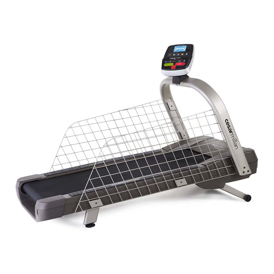
BEFORE YOU BEGIN Thank you for selecting the revolutionary PROFORM ® reading this manual, please see the front cover of this CESAR MILLAN PACK LEADER treadmill. The manual. To help us assist you, please note the product PACK LEADER treadmill offers an impressive selection model number and serial number before contacting us. -
Page 7: Part Identification Chart
PART IDENTIFICATION CHART Use the drawings below to identify small parts used for assembly. The number in parentheses below each draw- ing is the key number of the part, from the PART LIST near the end of this manual. The number following the key number is the quantity used for assembly. -
Page 8: Assembly
ASSEMBLY •• To hire an authorized service technician •• Left parts are marked ““L”” or ““Left”” and right parts to assemble your exercise equipment, call are marked ““R”” or ““Right.”” 1-800-445-2480. •• To identify small parts, see page 7. •• Assembly requires two persons. ••... -
Page 9: Identify The Right Upright (80). Have A Second
2. Make sure that the power cord is unplugged. Identify the Right Upright (80). Have a second person hold the Right Upright near the Frame (50). Wire See the inset drawing. Tie the wire tie in the Right Upright (80) securely around the end of the Upright Wire (78). - Page 10 4. Slide the upper end of the Left Upright (79) onto the bracket on the Right Upright (80), and have a second person hold the lower end of the Left Upright against the Frame (50). Make sure that Cutouts the Upright Wire (78) is in the cutouts and is not pinched.
- Page 11 6. Set the Console (72) face-down on a soft surface to avoid scratching the console. Attach the Console Bracket (73) to the Console (72) with four #8 x 1/2" Screws (4); do not over- tighten the Screws. 7. Have a second person hold the Console (72) Console near the Upright Wire (78).
- Page 12 8. Insert the wires into the Right Upright (80) as you set the Console Bracket (73) on the Uprights Console Wire (79, 80). Attach the Console Bracket (73) with three 5/16" x 2 1/2" Screws (3) and three 5/16" Star Washers (6);...
- Page 13 10. With the help of a second person, hold the Left Cage (69) against the Left Upright (79) and the Frame (50). Attach the Left Cage (69) with four 1/4" x 1 1/4" Screws (2), four Left Cage Brackets (81), two 81 2 Long Cage Spacers (84), and two Short Cage Spacers (83) as shown;...
- Page 14 12. See HOW TO MOVE THE TREADMILL on page 22. Move the treadmill to the desired location. Make sure that the leveling feet rest firmly on the floor. If the treadmill rocks even slightly, loosen one of the nuts, turn the leveling foot clockwise or counterclockwise until the rocking motion is eliminated, and then retighten the nut.
-
Page 15: Operation And Adjustment
OPERATION AND ADJUSTMENT HOW TO CONNECT THE POWER CORD nominal 120-volt circuit capable of carrying 15 or more amps. To avoid overloading the circuit, do Use a Surge Suppressor not plug other electrical devices, except for low- power devices such as cell phone chargers, into Your treadmill, like other electronic equipment, can be the surge suppressor or into an outlet on the same damaged by sudden voltage changes in your home’’s... - Page 16 CONSOLE DIAGRAM FEATURES OF THE CONSOLE The advanced console offers an array of features designed to make workouts for your dog more effective. When you use the manual mode of the console, you can adjust the speed and incline of the treadmill with the touch of a button.
- Page 17 HOW TO TURN ON THE POWER press the Home button on the console to select the manual mode. IMPORTANT: If the treadmill has been exposed to cold temperatures, allow it to warm to room tem- 3. Start the walking belt. perature before turning on the power.
- Page 18 The matrix offers several display tabs. Press the To exit the manual mode or a workout, press the increase and decrease buttons next to the Enter Home button. If necessary, press the Home button button or press the Display button until the desired again.
- Page 19 3. Start the workout. mill will automatically adjust to the speed and incline settings programmed for the next seg- Press the Start button or the Speed increase button ment. to start the workout. A moment after you press the button, the treadmill will automatically adjust to the To stop the workout at any time, press the Stop first speed and incline settings of the workout.
- Page 20 3. Start the workout. 4. Select an iFit workout. Press the Start button to start the workout. A To select an iFit workout, press one of the iFit but- moment after you press the button, the walking belt tons. Before some workouts will download, you will begin to move.
- Page 21 HOW TO CHANGE CONSOLE SETTINGS 5. Adjust the contrast level of the display if desired. The console features an information mode that allows you to view usage information, select a unit of mea- Press the decrease button to view the contrast surement, turn on or turn off the display demo mode, level.
-
Page 22: How To Move The Treadmill
HOW TO ADJUST THE CONSOLE The position of the console can be adjusted so that you can more easily operate it while you monitor your dog. To turn the console, hold the console with both hands and rotate it 90 degrees. Note: The console cannot be turned completely around. -
Page 23: Troubleshooting
TROUBLESHOOTING Most treadmill problems can be solved by follow- SYMPTOM: The console displays remain lit when ing the simple steps below. Find the symptom that you remove the key from the console applies, and follow the steps listed. If further assis- tance is needed, see the front cover of this manual. - Page 24 SYMPTOM: The walking belt slows when walked on SYMPTOM: The walking belt is off-center or slips when walked on a. Use only a surge suppressor that meets all of the specifications described on page 15. a. If the walking belt is off-center, first remove the key and UNPLUG THE POWER CORD.
- Page 25 NOTES...
- Page 26 NOTES...
-
Page 27: Part List
PART LIST Model No. CMTL59712.0 R0213A Key No. Qty. Description Key No. Qty. Description 3/8" x 4 1/2" Screw Platform Bracket 1/4" x 1 1/4" Screw Right Frame Cap 5/16" x 2 1/2" Screw Walking Belt #8 x 1/2" Screw Belt Guide 3/8"... -
Page 28: Exploded Drawing
EXPLODED DRAWING A Model No. CMTL59712.0 R0213A... - Page 29 EXPLODED DRAWING B Model No. CMTL59712.0 R0213A...
- Page 30 EXPLODED DRAWING C Model No. CMTL59712.0 R0213A...
- Page 31 EXPLODED DRAWING D Model No. CMTL59712.0 R0213A...
-
Page 32: Ordering Replacement Parts
ORDERING REPLACEMENT PARTS To order replacement parts, please see the front cover of this manual. To help us assist you, be prepared to pro- vide the following information when contacting us: •• the model number and serial number of the product (see the front cover of this manual) ••...
Need help?
Do you have a question about the CMTL59712.0 and is the answer not in the manual?
Questions and answers