Table of Contents

Related Manuals for urmet domus 1093/134M1


Summary of Contents for urmet domus 1093/134M1
-
Page 1: User Manual
Mod. 1093 DS1093-134A DAY & NIGHT IP MEGAPIXEL CAMERA IP BULLET CAMERA Ref. 1093/134M1 Ref. 1093/136M1 Ref. 1093/135M2 Ref. 1093/137M2 IP MINI DOME CAMERA IP VANDAL DOME CAMERA Ref. 1093/172M2 Ref. 1093/173M2 Ref. 1093/174M1 USER MANUAL... -
Page 2: Table Of Contents
Opening the Box ........................4 Warnings ...........................4 Device Installation .............................6 Schematic Diagram for Bullet IP Camera Ref. 1093/134M1 and Ref. 1093/135M2 ....6 Schematic Diagram for Bullet IP Camera Ref. 1093/136M1 and Ref. 1093/137M2 ....6 Schematic Diagram for Vandal Dome IP Camera Ref. 1093/173M2 ........7 Schematic Diagram for Mini Dome IP Camera Ref. -
Page 3: Introduction
INTRODUCTION Thank you for using IP Camera series products. Please carefully read the user manual before operation. As the software may be updated at any time, the contents of the operation manual are subject to change without prior notice. Note: : : : IP Camera refers to Internet Protocol Camera. -
Page 4: Product Description
PRODUCT DESCRIPTION URMET S.p.A. Ref. 1093/134M1, Ref. 1093/135M2, Ref. 1093/136M1, Ref. 1093/137M2, Ref. 1093/172M2, Ref. 1093/173M2, Ref. 1093/174M1 are IP MegaPixel camera which can be fully controlled via TCP/IP network connection. TECHNICAL FEATURES Hisilicon media processor with high performance and strong functions. - Page 5 Safety precautions Do not expose the device to rain or humidity and do not insert any solid or liquid object in it to prevent the risk of fire or electrocution. In these events disconnect the device from the electrical outlet and call technical assistance to check it.
-
Page 6: Device Installation
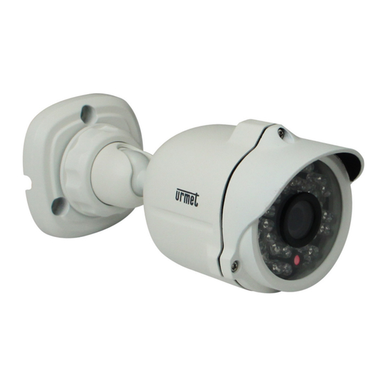
DEVICE INSTALLATION SCHEMATIC DIAGRAM FOR BULLET IP CAMERA REF. 1093/134M1 AND REF. 1093/135M2 Items Descriptions ①Front cover It can prevent the IP camera from the irradiation of the sunlight. ②Rear cover It is fixed with the front cover. ③Set screw Fix the front cover and rear cover. -
Page 7: Schematic Diagram For Vandal Dome Ip Camera Ref. 1093/173M2
SCHEMATIC DIAGRAM FOR VANDAL DOME IP CAMERA REF. 1093/173M2 ② ③ ① ④ ⑤ Items Descriptions ① Transparent cover Protect the hemisphere ② Infrared lamp Infrared LED lamp ③ Lens Lens of camera ④ Black inner cover Fix the hemisphere ⑤... -
Page 8: Schematic Diagram For Mini Dome Ip Camera Ref. 1093/172M2 And Ref. 1093/174M1
SCHEMATIC DIAGRAM FOR MINI DOME IP CAMERA REF. 1093/172M2 AND REF. 1093/174M1 ① ③ ② ④ ⑤ ⑥ Items Descriptions ① Lens Lens of camera ② Infrared lamp Infrared LED lamp ③ Hemisphere It is rotatable and used to adjust the installation angle ④... -
Page 9: Device Connection
DEVICE CONNECTION There are two types of connection: Connect the devicewith PC Connect IP camera with PC by network cable. The supply hub of IP camera is connected with DC 12V power supply. Set the IP of PC and that of IP camera in the same network segment. If the network is normal, wait for 1 minute after power on and IP camera will establish communictaion with PC. -
Page 10: Application Fields
APPLICATION FIELDS IP camera is usually applied in large-scale shopping malls, supermarkets, schools, plants, workshops, and other public places. As it has strong image processing capacity, IP camera can also be used in the environment requiring high definition of image, such as bank and traffic intersection. Refer to the following picture. Monitoring Center DS1093-134A... -
Page 11: Device Search Tool
DEVICE SEARCH TOOL The software can detect the IP address of IP camera in the LAN. Firstly, install .exe file (Device Search) in the included CD by the following procedures. Double click the .exe file Click [Next] to continue. DS1093-134A... - Page 12 Select installation folder and click [Next] to continue. Click [Install] to begin the installation. DS1093-134A...
- Page 13 Click [Finish] to finish the installation. Run the installed Device Search.exe software. Click to run the software and it will automatically display the IP address, subnet mask, gateway, port, version information and MAC address of the running IP camera in the current LAN, as shown in the following picture. DS1093-134A...
- Page 14 If the searched IP address and PC IP address are not in the same network segment, user may modify IP address, subnet mask, port number and other parameters of IP camera by using Device Search software. In the DeviceSearch software, select a device to modify IP address and then input new IP address, subnet mask, gateway, port number and administrator password(default: admin).
-
Page 15: Activex Control Setup
ACTIVEX CONTROL SETUP If the user visits IP camera with Internet Explorer for the first time, he has to install the plug-ins. For installing the plug- ins, it is necessary to set the browser security level. Enter menu [Tools/Internet Options/Security/Custom Level] and change “ActiveX controls and plug-ins”... -
Page 16: Webpage Configuration Of Ip Camera
WEBPAGE CONFIGURATION OF IP CAMERA LIVE Open Internet Explorer and input IP address of IP camera(http://192.168.1.168). The login dialog box will appear. See the following picture: User may select Stream Type and Quality Level in the login interface. Input user name(default: admin) and password (default: admin) Client Port, Language and click “Login” to enter the Live interface, as shown in the following picture. -
Page 17: Remote Settings
Other buttons on the Live interface: : : : :Enter the device setting menu and set customized parameters of the device; :Snapshot, file type, storage path, etc.; :Log out and return to the login interface; :It shows preview control buttons. From the left to the right, the names of buttons are play, stop, full screen, snapshot, start/stop recording, enable/disable talkback. - Page 18 Image Control Click【Display】→【Image Control】to enter the following interface.: IRCUT Mode: : : : 4 modes: GPIO Auto, Video Auto, Color Mode and Black & White Mode. IR-CUT Delay: : : : Set IRcut delay switching time Image flip: : : : Lens flip and angle flip Back light:...
-
Page 19: Network
Privacy Zone Click 【Display】→ 【Privacy Zone】 to enter the following interface: Set privacy zone: 1. Click to enable privacy zone. 2. Press and drag left mouse button to select privacy zone (4 zones at maximum). 3. Click Save to make the privacy zone effective. Delete:... - Page 20 Type: : : : DHCP or Static. Default type is Static. Client Port: : : : Client port of IPC Web Port: : : : Web port of IPC Mobile Port: : : : Connection port of mobile client IP address: : : : IP address of IPC Subnet Mask: Subnet mask of IPC Gateway:...
- Page 21 Email Click【Network】→【Email】 to enter the following interface: Email service setting. Apply this function with alarm function and the images captured during alarming can : be uploaded to E-mail server through network. Enable Email: Disable or enable SMTP Port: : : : Default value is 25 (E-mail service port) SMTP Server:...
- Page 22 DDNS Click【Network】→【DDNS】 to enter the following interface: : It refers to Dynamic Domain Name Server, which is used together with server for outer network accessing. Server: Select 3322, DynDNS, Changeip,NO-IP, DynDns, DDNS: Disable or enable URMET DDNS Host Name: Input the host name User Name: User’s name Password:...
- Page 23 The IP CAMERA parameters must be allocated manually if the network does not support DHCP. Select “Type = Static” on the “Menu Network” and fill in the following fields: IP address, subnet mask, gateway and DNS. Press APPLY to save the changes. IMPORTANT NOTE: The DNS fields must be filled in correctly for correct operation of the DDNS system.
- Page 24 Urmet DDNS Setup IMPORTANT NOTE: Before to get Urmet DDNS ID it is mandatory to modify the default password “admin” in a password with six chars. Check that the DDNS function is enabled and that the URMETDDNS server is selected. Click on the Get button and wait for ten seconds or so for the IP CAMERA ID to be generated.
- Page 25 IP Filter Click: Network: →: IP Filter to enter the following interface. Three modes: allow all IP connection, allow all set IP connection, and disable set IP connection. Add allowed IP or disabled IP Delete added IP DS1093-134A...
- Page 26 RTSP Click【Network】→【RTSP】to enter the following interface: RTSP:Enable or disable. Default setting is “Enable”. If it is set as “Disable”, user may not find through ONVIF. RTSP Port: Default value is 554. The value can be changed in the range of 1024-65535. After modification, the device will be restarted.
- Page 27 Click【Network】→【FTP】to enter the following interface: :FTP service setting. This function is applied together with alarming function. The captured images or alarming recording can be uploaded to FTP server through network. FTP: Disable or enable User Name: : : : User name for visiting FTP Password:...
- Page 28 GB28181 (For future Use) Click【Network】→【GB28181】to enter the following interface. The device supports GB28181 protocol. Click the option “Open and Effective” to enable the function. Set related registration information and click Save DS1093-134A...
-
Page 29: Alarm
8.2.3 ALARM Motion Click【Alarm】→【Motion】to enter the following interface: Setting procedure: : : : 1. Click to enable motion detection. 2. Click and drag left mouse button to select motion detection area. 3. Set motion detection sensitivity(Range:1-8. Larger number indicates higher sensitivity.) 4. -
Page 30: Device
Block Alarm (Feature not available for these IPC Series) Click【Alarm】→【Block Alarm】to enter the following interface: Alarm for blocking of camera lens It can link SMTP to send by Email. 8.2.4 DEVICE It contains【Log】and【Audio】. Their interfaces and descriptions are as follows. Click【Device】→【Log】to enter the following interface:... - Page 31 Audio (Feature not available for these IPC Series) Click【Device】→【Audio】to enter the following interface: IPC audio switch Audio setting procedure: : : : Click “Enable Audio” and audio setting options appears. User may set the input volume and output volume in the range of 0-10.
-
Page 32: System
8.2.5 SYSTEM System includes【Date/Time】,【Users】and【Info】. Refer to the following description. Date/Time Click【System】→【Date/Time】to enter the following interface: In this interface, user may set Date/Time, including System Time, Date Format and Time Format. After setting, click Save. The device also provides three kinds of automatic time synchronization: DST:... - Page 33 NTP: : : : Synchronize time with NTP server. Click NTP to enable NTP setting. Input NTP server address, select time zone and click Save. The system will automatically synchronize time with NTP server. Synchronize with computer time: : : : Device will take computer as the time server to synchronize time. Users Click【System】→【Users】to enter the following interface:...
- Page 34 Info Click【System】→【Info】to enter the following interface: It includes system information of the device, such as Device Type, MAC Address, Software Version, etc. DS1093-134A...
-
Page 35: Advanced
8.2.6 ADVANCED It includes【Firmware Update】,【Load Default】and【Maintain】, as shown in the following picture. Firmware Update Click【Advanced】→【Firmware Update】to enter the following interface: In “Firmware Update” option, user may click “Scan” to select update file, click Upgrade button and the system will be upgraded automatically. - Page 36 Load Default Click【Advanced】→【Load Default】to enter the following interface: In “Load Default” option, click the corresponding options and click Save to restore factory settings for the selected options. Maintain Click【Advanced】→【Maintain】to enter the following interface: In “Maintain” interface, user may set periodically reboot or manual reboot. DS1093-134A...
-
Page 37: Local Settings
LOCAL SETTINGS Click “Local Setting” to pop up the following dialog box: User may set Record Path, Download Path, Snapshot Path, File Type and Interval for manual recording. LOGOUT Click on in order to exit from IP Camera.Web Interface. DS1093-134A... -
Page 38: Software Mobile
SOFTWARE MOBILE Mobile Software is used for iOS Platform (iPhone, iPad) and Android Platform (Android Smartphone, Tablet). Here follow the Mobile Software Client description. IOS MOBILE About iOS Platform are available 2 App. Asee Software Mobile that use Mobile Port and iUVS Software that use Data Port. -
Page 39: Urmet Iuvs Software Mobile
9.1.2 URMET IUVS SOFTWARE MOBILE Urmet iUVS is a mobile phone CCTV application developed for iPhone OS. It's compatible with the URMET H.264 NVR Series. Features Here follow the main features of the application: Live audio/video streaming of up to 4 channels •... - Page 40 NOTE: It is needed to set the Data Port (i.e. 9000) for iUVS Software Mobile correct working. If the user sets the Mobile Port, iUVS Software Mobile cannot work for any reason. To delete a device from list, swipe the device name you want to delete, then tap the delete button next to the device name. Live video monitor Tab Live Monitor on Main Menu will bring up Live interface, which provides stream video, record, snapshot and PTZ, etc.
- Page 41 Remote Playback Tab Remote Playback on Main Menu will show the playback entry. you will be able to play one channel of remote device after 2 steps. 1. Select one channel Tab Select channel button to open device list as below, then select one channle of device in the list. 2.
-
Page 42: Android Mobile
Video snapshot On live monitoring, Tap will show up 5 label on bottom panel, then you can take snapshots by tap the labels. PTZ control PTZ is Pan-Tilt-Zoom and reflects the movement options of the camera. Tap to open PTZ mode, it will bring up PTZ control buttons on the bottom of live page. -
Page 43: Asee Software Mobile
9.2.1 ASEE SOFTWARE MOBILE Please make sure the software environment support on your Android Mobile, such as Apkinstaller. Make sure your mobile have been connected to network and could download the software. Enter into [Program] option and highlight [E-market] icon shown as Picture above. Enter into the [E-market] interface shown as Picture above. -
Page 44: Urmet Iuvs Software Mobile
CHs Select PTZ Direction Zoom+/- Focus+ - Iris +/- Function buttons from left to right in turn are: Play/Pause, Snapshot, setup, Next CHs Group and help. 12. Setting Menu Address: Enter the IP address of the NVR Port: Enter the Mobile Port No. Of the NVR Device Name: Enter NVR name (User defined) User ID: Enter the User’s Name Password: Enter the User’s Password... - Page 45 Add and delete device Device manager allow you add or delete device, and also modify device properties. Tab "Device Manager" on Main Menu to open this interface as below To add a new device, click "Add" button at the top right, then you can input the device name, address (IP, domain name or Device ID for Urmet DDNS Account), port, user name and password etc.
- Page 46 1. Open a device to open device list as below, then select one of devices in the list, will open all channels of it automatically. 2. Open a channel Tab Cross button on one of the view window will enter channel list window, then select one channel to open on the previous window.
- Page 47 Remote Playback Tab Remote Playback on main menu will bring up a calendar view which uses black point to presents the day of month there is Record Videos. Press 'Select Channel' button to retrieve the Record Videos of channel from device. DS1093-134A...
- Page 48 PTZ control PTZ is Pan-Tilt-Zoom and reflects the movement options of the camera. Tap to open PTZ mode, it will bring up PTZ control buttons on the bottom of live page. You need to Maximize a camera window and open PTZ mode to control the camera. Tab Arrows on the side of camera window to control camera move side to side or up and down.
-
Page 49: Technical Specifications For Bullet Ip Camera
10 TECHNICAL SPECIFICATIONS FOR BULLET IP CAMERA Descriptions Items 1093/134M1 1093/136M1 1093/135M2 1093/137M2 Image Sensor CMOS Sensor 1.0 MPX 1/4’ 1.3MPX 1/3’ 3.0 MPX 1/3’ 3.0 MPX 1/3’ Sensor Type OV9712 Ar0130 Ar0330 Ar0330 Video Format P/N adaptive control 0.08Lux (F1.2,AGC ON) -
Page 50: Technical Specifications For Mini Dome/Vandal Dome Ip Camera
11 TECHNICAL SPECIFICATIONS FOR MINI DOME/VANDAL DOME IP CAMERA Descriptions Items Mini Dome Vandal Dome 1093/172M2 1093/174M1 1093/173M2 Image Sensor CMOS Sensor Sensor Type 3.0 MPX 1/3’ Ar0330 1.3 MPX 1/3’ Ar0130 3.0 MPX 1/3’ Ar0330 Video Format P/N adaptive control Minimum luminance 0.03Lux @(F1.2, AGC ON) ,0 Lux with IR Internal,... -
Page 51: Appendix
12 APPENDIX 12.1 ROUTER PORT FORWARDING If user wants to remotely visit IP Camera monitoring image through internet, he has to open web port and client port of IP Camera. Take Cisco router as an example: address 192.168.1.168, port 8000 client port 9988.。... -
Page 52: Faq
12.2 FAQ ◆ IE cannot load and install plug-ins. Possible cause IE security level is set too high. Solution Set IE security level to the minimum level. ◆ After updating, user cannot visit IP Camera through IE. Solution Clear IE cache. Specific steps: Open IE Tools, open Internet option, click “delete file” button in the option (temporary Internet files), click “delete all offline contents”, and click OK.
Need help?
Do you have a question about the 1093/134M1 and is the answer not in the manual?
Questions and answers