Table of Contents
Advertisement
Advertisement
Table of Contents

Related Manuals for Dell Networking S4048


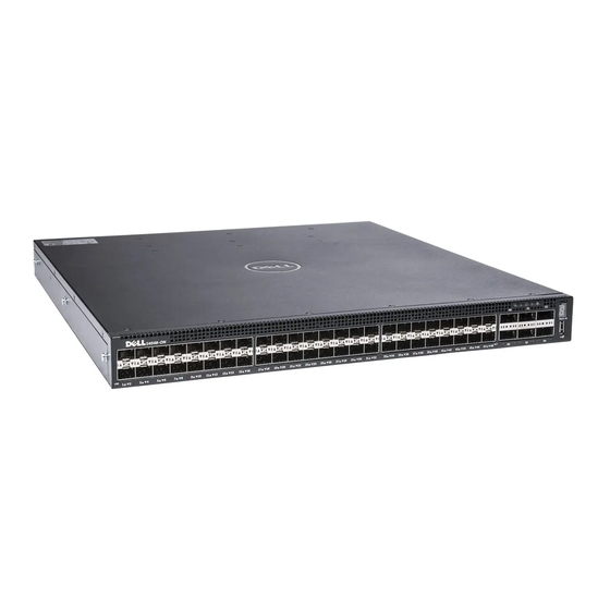
Summary of Contents for Dell Networking S4048
- Page 1 Dell Networking S4048–Open Networking (ON) Installation Guide January 2017...
- Page 2 A WARNING indicates a potential for property damage, personal injury, or death. Copyright © 2017 Dell Inc. or its subsidiaries. All rights reserved. Dell, EMC, and other trademarks are trademarks of Dell Inc. or its subsidiaries. Other trademarks may be trademarks of their respective owners.
-
Page 3: Table Of Contents
Contents 1 About this guide............................. 5 Related documents................................5 2 The S4048–ON system..........................6 Introduction..................................6 Features....................................7 Physical dimensions................................7 System status..................................8 LED display..................................8 LED behavior................................9 Prerequisites..................................10 S4048–ON configurations............................... 11 3 Site preparations............................12 Site selection..................................12 Cabinet placement................................12 Rack mounting.................................. - Page 4 Safety Standards and Compliance Agency Certifications..................41 Electromagnetic Compatibility (EMC)........................41 Product Recycling and Disposal..........................42 10 Technical Support............................43 The Dell Support Website............................... 43 Accessing Support Services............................. 43 Contacting the Technical Assistance Center........................43 Requesting a Hardware Replacement........................... 44 Contents...
-
Page 5: About This Guide
Avoid exposure to laser radiation and do not stare into open apertures. Related documents For more information about the S4048–ON system, see the following documents: • Dell Networking S4048–Open Networking (ON) Getting Started Guide • Dell Networking S4048–Open Networking (ON) Release Notes •... -
Page 6: The S4048-On System
The S4048–ON system The following sections describe the Dell S4048–ON system: Topics: • Introduction • Features • Physical dimensions • System status • LED display • Prerequisites • S4048–ON configurations Introduction S4048-ON is a networking switch for campus aggregation and core switching 10 Gbps servers and 40 Gbps optical uplinks to the 40 Gbps switching fabric in the core. -
Page 7: Features
SFP+ ports QSFP+ ports USB Type-A storage port MicroUSB console port Figure 3. S4048–ON PSU-side view Power supply unit 1 Fan module Out-of-band management port Power supply unit 2 RS-232 serial console port Features The S4048–ON offers the following features: •... -
Page 8: System Status
System status You can view S4048–ON status information using the light emitting diodes (LEDs). LED display The S4048–ON includes LED displays on both the I/O Port and PSU side of the chassis, as shown. For LED information, see your third-party operating software documentation. Figure 4. -
Page 9: Led Behavior
LED behavior The following S4048–ON system LED behavior is seen during open networking installation environment (ONIE) operations: Figure 5. S4048–ON LEDs Master LED System LED Power LED Fan LED Locator LED SFP+ link/activity LEDs Stack LED USB port LED QSFP+ link/activity LEDs Table 1. -
Page 10: Prerequisites
Description FAN LED • Solid green—fan powered and running at the expected RPM • Solid amber—fan failed including incompatible airflow direction when you insert the PSU or fan trays with differing airflows PSU LED • Solid green—Normal operation • Solid amber—Power supply critical event causing a shutdown •... -
Page 11: S4048-On Configurations
• Mounting brackets for rack installation, included • Screws for rack installation • #1 and #2 Phillips screwdrivers, not included • Torx screwdriver, not included • Ground cable screws, included • Copper/fiber cables Other optional components are: • Ground cable •... -
Page 12: Site Preparations
Storing components Site selection Install Dell equipment in restricted access areas. A restricted access area is one in which service personnel can only gain access using a special tool, lock, key or other means of security and access is controlled by the authority responsible for the location. -
Page 13: Rack Mounting
Use the power supply cord as the main disconnect device on the AC system. Ensure that the socket-outlet is located/ installed near the equipment and is easily accessible. Storing components If you do not install your S4048–ON and components immediately, Dell recommends properly storing the system and all optional components by following these guidelines. •... - Page 14 • Store on a dry surface or floor, away from direct sunlight, heat, and air conditioning ducts. • Store in a dust-free environment. NOTE: ESD damage can occur when components are mishandled. Always wear an ESD-preventive wrist or heel ground strap when handling the S4048–ON and its accessories.
-
Page 15: Nebs Compliance
NEBS compliance For your system to be network equipment building system (NEBS) compliant, you must follow the instructions detailed in this section. To be NEBS compliant, orient your system in the rack so that the air inlet is from the front aisle and the air exhaust is to the back aisle. Important information WARNING: The SFP+, QSFP, QSFP28, console, Ethernet management, and universal serial bus (USB) ports are suitable for... -
Page 16: S4048-On Installation
S4048–ON installation To install the S4048–ON system, Dell recommends completing the installation procedures in the order presented in this chapter. Always handle the S4048–ON and its components with care. Avoid dropping the system or its field replaceable units (FRUs). NOTE: ESD damage can occur if components are mishandled. -
Page 17: Rack Or Cabinet Hardware Installation
You may either place the switch on the rack shelf or mount the switch directly into a 19" wide, EIA-310- E-compliant rack—four-post, two- post, or threaded methods. The Dell ReadyRails™ system is provided for one 1U front-rack and two-post installations. -
Page 18: Two-Post Flush-Mount Configuration
Figure 6. 1U tool-less configuration Align and seat the front flange pegs in the holes on the front side of the vertical post, item 2. Repeat this procedure for the second rail. To remove each rail, pull on the latch release button on each flange ear and unseat each rail, item 3. Two-post flush-mount configuration CAUTION: Your system is not NEBS Earthquake Z4-compliant if you use this installation method. -
Page 19: Two-Post Center-Mount Configuration
Figure 7. Two-post flush-mount configuration Attach one rail to the front post flange with two user-supplied screws, item 2. Slide the plunger bracket forward against the vertical post and secure the plunger bracket to the post flange with two user-supplied screws. -
Page 20: Four-Post Threaded Configuration
Figure 8. Two-post center-mount configuration Slide the back bracket towards the post and secure it to the post flange with two user-supplied screws, item 2. Repeat this procedure for the second rail. Four-post threaded configuration CAUTION: To be NEBS Earthquake Z4-compliant, you must remove the tool-less latch castings described in Step 1. For this configuration, remove the latch castings from each end of the ReadyRails assemblies. -
Page 21: S4048-On Installation
Figure 9. Four-post threaded configuration For each rail, attach the front and rear flanges to the post flanges with two user-supplied screws at each end, item 2. S4048-ON installation You can mount the system in the 1U front-rack or 1U flush and center two-post configurations. The following is an example of a front-rack configuration: For the 1U flush and center two-post configurations, slide the system into the rails in the same manner as the four-post configurations. - Page 22 Figure 10. Switch rails attachment After you have installed both switch rails, line them up on the previously mounted Ready-Rails and slide the switch in until it is flush with front of rack. About 3 inches before you fully insert your system, the rail locking feature engages to keep the switch from inadvertently sliding out of the rack and falling.
-
Page 23: Ground Cable
Dell recommends grounding your system. To attach the ground cable to the chassis, use a single M4x0.7 screw. The cable itself is not included with the S4048–ON. To properly ground the chassis, Dell Networking recommends using a 6 AWG one-hole lug, #10 hole size, 63"... -
Page 24: Qsfp+ Optic Replacement
System power-up Supply power to the S4048–ON after it is mounted in a rack or cabinet. Dell recommends re-inspecting your system before powering up. Verify the following: • The equipment is properly secured to the rack and properly grounded, optional. -
Page 25: Power Supplies
The PSUs are field replaceable. When running with full redundancy—two power supplies installed and running, you can remove and replace one PSU without disrupting traffic. NOTE: If you use a single PSU, install a blank plate in the other PSU slot. Dell Networking recommends using power supply 2 (PSU2) as the blank plate slot. NOTE: ESD damage can occur if components are mishandled. -
Page 26: Ac Power Supply Installation
NOTE: If you use a single PSU, install a blank plate in the other PSU slot. If you are only using one power supply, Dell recommends installing the power supply in the first slot (PSU1) and installing a blank plate in the second slot (PSU2). -
Page 27: Ac Power Supply Replacement
NOTE: If you use a single PSU, install a blank plate in the other PSU slot. If you are only using one power supply, Dell recommends installing the power supply in the first slot (PSU1) and installing a blank plate in the second slot (PSU2). - Page 28 Figure 14. S4048–ON DC power supplies Power supply 1 Power supply 2 Remove the PSU slot cover from the S4048-ON. Remove the PSU from the electro-static bag. Insert the PSU into the switch PSU slot. Insert the PSU exposed PCB edge connector first. The PSU slot is keyed so that the PSU inserts fully in one orientation only.
-
Page 29: Dc Power Connections
NOTE: The S4048-ON powers up when the cables are connected between the power supply and the power source. The PSUs have an integrated fan, which you cannot replace individually; if the fans integrated in a PSU fail, replace the entire PSU. However, you can replace the fan trays individually. -
Page 30: Dc Labels
DC labels Attach the DC rating labels to the S4048–ON Regulatory label on the bottom of the switch. Find the two DC power and DC input rating labels included with the DC power supply kit, as shown. Locate the regulatory label on the bottom of the switch. Attach the DC power label and input rating label over the AC power label and input rating label outlined in red, as shown. -
Page 31: Fans
Fans The S4048–ON comes from the factory with one PSU and three fan modules installed in the chassis. The fan modules and the power supplies, which have integrated fans, are hot-swappable. NOTE: To run the system, the three fan slots must have operating fan units. If you do not install a module in each slot, the system shuts down in one minute. -
Page 32: Fan Module Installation
Fan modules Fan module installation The fan modules in the S4048–ON are field replaceable. Module slot 1 is on the left side of the chassis, module slot 2 is in the middle of the chassis, and module slot 3 is on the right side of the chassis. -
Page 33: Management Ports
Management ports Besides the 10 GbE and 40 GbE switch ports, the S4048–ON system provides several ports for management and storage. Topics: • RS-232 console port access • Micro USB-B console port access • Before you install an OS RS-232 console port access The RS-232 console port is on the PSU-side of the S4048-ON chassis, as shown. -
Page 34: Mounting The Usb Storage
Connect the MicroUSB-B end of cable into the MicroUSB-B console port on the S4048-ON. Power on the S4048-ON. Install the necessary USB device drivers. To download the drivers, go to www.dell.com/support. For assistance, contact Dell Technical Support. Open your terminal software emulation program to access the S4048-ON. -
Page 35: Before You Install An Os
NOTE: The following message displays if the /mnt/usb directory is missing: mount: mounting /dev/sdb on /mnt/usb failed: No such file or directory. NOTE: The following message displays if the USB device is not seen: mount: mounting /dev/sdb on /mnt/usb failed: No such device or address. OPTIONAL: Add a device to the file systems table (fstab) and mount the file systems. -
Page 36: Onie Service Discovery On The S4048-On System
For downloading and updating ONIE from a URL and erases any installed OS ONIE: Diag ONIE Run Diagnostic package for S4048-ON During initial setup, the system boots to ONIE Install. ONIE Install boots with ONIE Discovery to the console (ONIE:). ONIE Service Discovery on the S4048–ON System ONIE attempts to locate the installer through a number of discovery methods, as shown. -
Page 37: Specifications
Specifications This chapter lists the S4048–ON specifications. CAUTION: Operate the product at an ambient temperature not higher than 113°F (45°C). CAUTION: Lithium Battery Caution: There is a danger of explosion if the battery is incorrectly replaced. Replace only with same or equivalent type of battery. -
Page 38: Ieee Standards
Table 7. AC power requirements Parameter Specifications Power supply 100–240 VAC 50/60 Hz 5.8 A @ 398.02 watts/100vac Maximum current draw per system 2.9 A @ 398.02 watts/200vac Maximum power consumption 460 Watts Typical power consumption 338 Watts Reliability MTBF 355.178 hours IEEE standards The S4048–ON complies with the following IEEE standards: •... -
Page 39: European Union Emc Directive Conformance Statement
Properly shielded and grounded cables and connectors must be used in order to meet FCC emission limits. Dell Networking is not responsible for any radio or television interference caused by using other than recommended cables and connectors or by unauthorized changes or modifications in the equipment. -
Page 40: Japan: Vcci Compliance For Class A Equipment
(VCCI). If this equipment is used in a domestic environment, radio disturbance may arise. When such trouble occurs, the user may be required to take corrective actions. WARNING: Use the AC power cords with Dell Networking equipment only. Do not use Dell Force10 AC power cords with any unauthorized hardware. Figure 24. Japan: Warning Label Korean Certification of Compliance Figure 25. -
Page 41: Safety Standards And Compliance Agency Certifications
Figure 26. Korean Package Label Safety Standards and Compliance Agency Certifications • CUS UL 60950-1, 2nd Edition • CSA 60950-1-03, 2nd Edition • EN 60950-1, 2nd Edition • EN 60825-1, 1st Edition • EN 60825-1 Safety of Laser Products—Part 1: Equipment Classification Requirements and User’s Guide •... -
Page 42: Product Recycling And Disposal
WEEE. Customer participation is important to minimize any potential effects of EEE on the environment and human health due to the potential presence of hazardous substances in EEE. Dell Networking products, which fall within the scope of the WEEE, are labeled with the crossed-out wheelie-bin symbol, as shown above, as required by WEEE. -
Page 43: Technical Support
Accessing Support Services The URL for Dell Support is http://www.dell.com/support. You must have a user id and password to access Dell Support services. If you do not have a user id and password, you can request these at the website. -
Page 44: Requesting A Hardware Replacement
Request an RMA number from TAC by opening a support case. Open a support case by: • Using the Create Service Request form on the iSupport page. • Contacting Dell Networking directly by email or by phone. • Provide the following information when using email or phone: •...
Need help?
Do you have a question about the Networking S4048 and is the answer not in the manual?
Questions and answers