
Related Manuals for Dell S4148FE


Summary of Contents for Dell S4148FE
- Page 1 S4100–ON Series S4128F-ON, S4148F-ON, and S4148FE Installation Guide November 2017...
- Page 2 A WARNING indicates a potential for property damage, personal injury, or death. Copyright © 2017 Dell Inc. or its subsidiaries. All rights reserved. Dell, EMC, and other trademarks are trademarks of Dell Inc. or its subsidiaries. Other trademarks may be trademarks of their respective owners.
-
Page 3: Table Of Contents
Contents 1 About this guide............................. 5 Related documents................................5 Information symbols................................5 2 S4100–ON Series switch..........................7 Introduction..................................7 Features....................................9 Physical dimensions................................10 LED display..................................10 LED behavior................................10 Prerequisites..................................14 S4100-ON Series configurations............................ 14 Luggage tag..................................15 3 Site preparations............................17 Site selection..................................17 Cabinet placement................................18 Rack mounting.................................. - Page 4 Safety standards and compliance agency certifications.....................46 Electromagnetic compatibility............................46 Emissions..................................46 Immunity..................................46 Product recycling and disposal............................47 Waste Electrical and Electronic Equipment (WEEE) directive for recovery, recycle, and reuse of IT and telecommunications products...........................47 9 Dell EMC support............................48 Contents...
-
Page 5: About This Guide
• Dell Open Networking Hardware Diagnostic Guide • S4100-ON Series Release Notes NOTE: For the most recent documentation, visit Dell EMC support: www.dell.com/support. Information symbols This book uses the following information symbols: NOTE: The Note icon signals important operational information. - Page 6 WARNING: The Warning icon signals information about hardware handling that could result in injury. WARNING: The ESD Warning icon requires that you take electrostatic precautions when handling the device. About this guide...
-
Page 7: S4100-On Series Switch
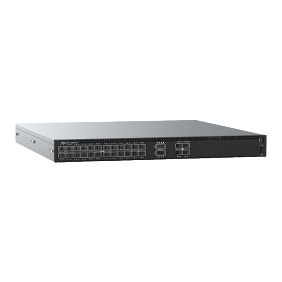
Luggage tag Introduction The S4100-ON Series (S4128F-ON, S4148F-ON, and S4148FE-ON) is a one rack unit (RU), full-featured fixed form-factor top-of-rack (ToR) 10/25/40/50/100GbE switch for 10G servers with small form-factor pluggable plus (SFP+), quad small form-factor pluggable plus (QSFP+), and quad small form-factor pluggable (QSFP28) ports. The S4148FE-ON also includes unified (Fibre channel and Ethernet) 10GbE SFP+ and QSFP28 ports. - Page 8 • 4 fixed 100GbE QSFP28 ports • seven-segment stacking indicator • 1 micro-USB-B console port • 1 USB type-A port S4148FE-ON • 48 fixed 10GbE SFP+ ports • 2 fixed 40GbE QSFP+ ports • 4 fixed 100GbE QSFP28 ports •...
-
Page 9: Features
S4148F-ON: 48 fixed 10GbE SFP+ ports, 2 fixed 40GbE QSFP+ ports, 4 fixed 100GbE QSFP28 ports • S4148FE-ON: 48 fixed 10GbE SFP+ ports, 2 fixed 40GbE QSFP+ ports, 4 fixed 100GbE QSFP28 ports with support for LRM optics • One MicroUSB-B serial console management port •... -
Page 10: Physical Dimensions
Power supply unit (PSU) and fan module handle: 1.57 inches (40 mm) LED display The S4100–ON Series (S4128F-ON, S4148F-ON, and S4148FE-ON) contains LED displays on the I/O side and PSU side of the switch. NOTE: If you are using third-party software, for more LED information, see their operating software documentation. - Page 11 Figure 7. S4148F-ON and S4148FE-ON I/O-side LEDs QSFP28 port activity LEDs Link/activity port LEDs Master LED System LED Power LED Fan LED Locator LED/System beacon Stack ID Figure 8. S4100-ON Series PSU-side LEDs Fan LED Link LED PSU LED Activity LED Table 3.
- Page 12 Description Master LED • Off—Switch is in Stacking Slave mode • Solid green—Switch is in Stacking Master or Standalone mode FAN LED • Off—No power • Solid green—Normal operation; fan powered and running at the expected RPM • Solid yellow—Fan failed—including incompatible airflow direction when you insert the PSU or fan trays with differing airflows PSU LED...
- Page 13 Description • Flashing yellow, 1 second on/off—Port beacon Activity LED • Off—No link • Flashing green—Port activity NOTE: There are four LEDs for each QSFP+, QSFP28, and unified QSFP28 port. For each port, 100GbE or 40GbE uses only one LED, 2x50GbE uses two LEDs, and 4x25GbE or 4x10GbE uses all four LEDs. Table 6.
-
Page 14: Prerequisites
Flashing yellow—Link activity at a lower speed—1G port • Flashing yellow, 1 second on/off—Port beacon Prerequisites The following is a list of required and optional components for the S4100–ON Series (S4128F-ON, S4148F-ON, and S4148FE-ON) switch: NOTE: Detailed installation instructions are provided in the Site preparations S4100-ON Series installation sections. -
Page 15: Luggage Tag
Luggage tag The S4100–ON Series (S4128F-ON, S4148F-ON, and S4148FE-ON) switch has a pull-out tag, known as a luggage tag, on the PSU-side of the switch. The front of the luggage tag includes switch ID information. The back of the luggage tag includes a QRL that takes you to a How-To site where you watch videos about racking the switch, replacing components, configuring port channels, and so on. - Page 16 Figure 9. S4100–ON Series luggage tag Front: MAC address Front: Service tag and Express service code Back: Quick resource locator (QRL) Back: QRL S4100–ON Series switch...
-
Page 17: Site Preparations
Site preparations The S4100–ON Series (S4128F-ON, S4148F-ON, and S4148FE-ON) is suitable for installation as part of a common bond network (CBN). You can install the switch in: • Network telecommunication facilities • Data centers • Other locations where the National Electric Code (NEC) applies For more information about the S4100–ON Series specifications, see Specifications. -
Page 18: Cabinet Placement
Cabinet placement Install the S4100–ON Series (S4128F-ON, S4148F-ON, and S4148FE-ON) only in indoor cabinets designed for use in a controlled environment. Do not install the switch in outside cabinets. For cabinet placement requirements, see Site selection. The cabinet must meet minimum size requirements. Airflow must be in accordance with the Electronic Industries Alliance (EIA) standard. -
Page 19: Storing Components
Module power is software controlled. You do not see module LEDs when the switch powers up in ONIE. Storing components If you do not install your S4100–ON Series (S4128F-ON, S4148F-ON, and S4148FE-ON) switch and components immediately, properly store the switch and all optional components following these guidelines: •... -
Page 20: S4100-On Series Installation
S4100–ON Series installation To install the S4100–ON Series (S4128F-ON, S4148F-ON, and S4148FE-ON), complete the installation procedures in the order presented in this section. Always handle the S4100–ON Series switch and its components with care. Avoid dropping the switch or any field replaceable units (FRUs). -
Page 21: Rack Or Cabinet Installation
Do not mount the equipment with the fan panel facing downward. ReadyRails installation To easily configure your rack for installation of your S4100–ON Series (S4128F-ON, S4148F-ON, and S4148FE-ON) switch, use the ReadyRails rack mounting system provided. You can install the ReadyRails system using the 1U tool-less square-hole method or one of three possible 1U threaded round-hole methods. -
Page 22: 1U Tool-Less Mount Installation
Figure 10. Separate rails 1U Tool-less mount installation NOTE: For more installation instructions, see the installation labels attached to the rail assembly. Face the ReadyRails flange ears facing outward. Place one rail between the left and right vertical posts. Align and seat the back flange rail pegs in the back vertical post flange. -
Page 23: Two-Post Flush-Mount Installation
Figure 11. 1U tool-less installation Align and seat the front flange pegs in the holes on the front side of the vertical post. NOTE: Be sure that the rails click into place and are secure. Repeat this procedure for the second rail. To remove each rail, pull on the latch release button on each flange ear and unseat each rail. -
Page 24: Two-Post Center-Mount Installation
Figure 12. Two-post flush-mount installation Attach one rail to the front post flange with two user-supplied screws, item 2. Slide the plunger bracket forward against the vertical post and secure the plunger bracket to the post flange with two user-supplied screws, see item 3. -
Page 25: Four-Post Threaded Installation
Figure 13. Two-post center-mount installation Slide the back bracket towards the post. Secure it to the post flange with two user-supplied screws, items 2 and 3. Repeat this procedure for the second rail. Four-post threaded installation NOTE: For more installation instructions, see the installation labels attached to the rail assembly. Remove the latch castings from each end of the ReadyRails assemblies. -
Page 26: S4100-On Series Installation
For more information, see the installation instruction labels on the rail. Attach the inner switch rails to the S4100F–ON Series (S4128F-ON, S4148F-ON, and S4148FE-ON) switch. Line up the rail with the mounting heads and attach the rail to the chassis. Slide the rail back until it locks into place. The following shows the detail of the front standoff with the locking tab: S4100–ON Series installation... - Page 27 Figure 15. Switch rail attachment After you install both rails, line them up on the ReadyRails. Slide the switch in until it is flush with the front of rack. About three inches before you fully insert your switch, the rail locking feature engages to keep the switch from inadvertently sliding out and falling.
-
Page 28: Optics Installation
To remove the chassis from the rack or cabinet, press in the two side-release bars on the chassis at the same time and slide the chassis forward. Optics installation The S4100-ON Series (S4128F-ON, S4148F-ON, and S4148FE-ON) switch has the following optic configurations: Table 12. S4100-ON Series optic configurations Platform... -
Page 29: Optics Removal
Do not jerk or tug repeatedly on the tab. Switch power-up Supply power to the S4100–ON Series (S4128F-ON, S4148F-ON, and S4148FE-ON) switch after you mount it in a rack or cabinet. Dell EMC recommends reinspecting your switch before powering up. Verify the following: •... -
Page 30: After Switch Installation
(ONIE)-compatible operating system documentation at www.onie.org. For more information about working with the ONIE environment, see your switch documentation at www.dell.com/support. Switch replacement The following steps describe removing and replacing a switch. For further assistance when replacing a switch, contact your Dell EMC support representative. NOTE: ESD damage can occur when components are mishandled. -
Page 31: Power Supplies
Power supplies The S4100–ON Series (S4128F-ON, S4148F-ON, and S4148FE-ON) switch ships with two AC or DC power supplies. The power supplies have two air-flow directions, normal and reverse. Normal is from the I/O-side to the PSU-side. Reverse is from the PSU-side to the I/O-side. -
Page 32: Psu Leds
NOTE: If you use a single PSU, install a blank plate in the other PSU slot. If you are only using one power supply, Dell EMC recommends installing the power supply in the first slot, PSU1. Install a blank plate in the second slot, PSU2. -
Page 33: Ac Or Dc Power Supply Replacement
NOTE: If you use a single PSU, install a blank plate in the other PSU slot. If you are only using one power supply, Dell EMC recommends installing the power supply in the first slot, PSU1. Install a blank plate in the second slot, PSU2. - Page 34 Figure 19. DC power supply and connector cable DC PSU power socket Cable connector with thumb screws Cable connector wires—black, green, and blue Wiring block DC power source wires—black, green, blue Strip 1/2 inches of insulation from each of the site’s DC power source wires, item 5. Insert each of the site’s DC power source’s bare wire lengths into the wiring block, matching the wire colors, items 3 and 4.
-
Page 35: Fans
Fans The S4100–ON Series (S4128F-ON, S4148F-ON, and S4148FE-ON) switch comes from the factory with two PSUs and four fan modules installed in the chassis. The fan modules and the power supplies are hot-swappable. In addition to the power supply modules, you can order and install fan modules separately. -
Page 36: Fan Leds
Fan module installation The fan modules in the S4100–ON Series (S4128F-ON, S4148F-ON, and S4148FE-ON) switch are field replaceable. When looking at your switch, Slot 1 is on the left side of the switch and Slot 4 is on the right side of the switch. -
Page 37: Management Ports
Management ports Besides the 10/100/1000Base-T RJ-45 ports, the S4100–ON Series (S4128F-ON, S4148F-ON, and S4148FE-ON) switch provides several ports for management and storage. NOTE: The output examples in this section are for reference only. Your output may vary. Topics: • RS-232 console port access •... -
Page 38: Usb Storage
• 1 stop bit • No flow control USB storage USB storage does not automatically mount. The supported file system is FAT. To use USB storage, first mount the device using the following steps: Create a mount directory for the USB. ONIE:/ # mkdir /mnt/usb View the fixed disks using fdisk. -
Page 39: Before You Install An Os
No flow control Before you install an OS After powering on the S4100–ON Series (S4128F-ON, S4148F-ON, and S4148FE-ON) switch, it goes through a power-on self-test (POST). POST runs every time the switch is initialized and checks the hardware components to determine if the switch is fully operational before booting. -
Page 40: Onie Service Discovery
Open Networking Hardware Diagnostic Guide . NOTE: For more information, see the After you have securely installed and powered on the switch, to configure your switch, see your third-party ONIE-compatible OS or the Dell EMC OS documentation. ONIE service discovery ONIE attempts to locate the installer through several discovery methods, as shown. - Page 41 64 bytes from 10.11.8.12: seq=0 ttl=62 time=1.357 ms 64 bytes from 10.11.8.12: seq=1 ttl=62 time=0.577 ms Management ports...
-
Page 42: Specifications
Specifications This section lists the S4100–ON Series (S4128F-ON, S4148F-ON, and S4148FE-ON) switch specifications. CAUTION: Operate the product at an ambient temperature not higher than 113°F—45°C. CAUTION: Lithium Battery Caution: There is a danger of explosion if the battery is incorrectly replaced. Replace only with same or equivalent type of battery. -
Page 43: Ieee Standards
Input current at full load −40.5V/23.8A −48V/19.0A −60V/ 15.6A, without fan −40.5V/24.0A −48V/19.2A −60V/ 16.0A, with fan IEEE standards The S4100–ON Series (S4128F-ON, S4148F-ON, and S4148FE-ON) switch complies with the following IEEE standards: • 802.1ab (LLDP) • 802.1ax (Layer 2) -
Page 44: Agency Compliance
Properly shielded and grounded cables and connectors must be used in order to meet FCC emission limits. Dell EMC is not responsible for any radio or television interference caused by using other than recommended cables and connectors or by unauthorized changes or modifications in the equipment. -
Page 45: Japan Vcci Compliance For Class A Equipment
(VCCI). If this equipment is used in a domestic environment, radio disturbance may arise. When such trouble occurs, the user may be required to take corrective actions. WARNING: Use the AC power cords with Dell EMC equipment only. Do not use Dell EMC AC power cords with any unauthorized hardware. Figure 25. Japan: warning label Korean certification of compliance Figure 26. -
Page 46: Safety Standards And Compliance Agency Certifications
Figure 27. Korean package label Safety standards and compliance agency certifications • IEC 62368-1, 2nd Edition • CUS UL 60950-1, 2nd Edition • Meets or exceeds Hi Pot and Ground Continuity testing per UL 60950-1. • AS/NZS 60950 • CSA 60950-1-03, 2nd Edition •... -
Page 47: Product Recycling And Disposal
You must recycle or discard this system according to applicable local and national regulations. Dell EMC encourages owners of information technology (IT) equipment to responsibly recycle their equipment when it is no longer needed. Dell EMC offers a variety of product return programs and services in several countries to assist equipment owners in recycling their IT products. -
Page 48: Dell Emc Support
The Dell EMC support site provides integrated, secure access to these services. To access the Dell EMC support site, go to www.dell.com/support/. To display information in your language, scroll down to the bottom of the web page and select your country from the drop-down menu.
Need help?
Do you have a question about the S4148FE and is the answer not in the manual?
Questions and answers