Table of Contents
Advertisement
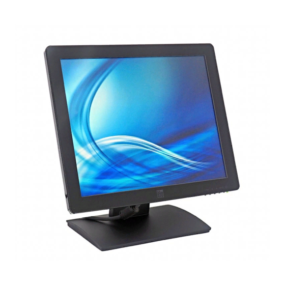
ET1517L and ET1717L Touchmonitors
Part Description
ET1517L-7UWA-1 -GY-ZB-G
ET1517L-7UWA-1 -WH-ZB-G
ET1517L-8UWA-0 -GY-ZB-G
ET1517L-8UWA-0 -WH-ZB-G
ET1717L-7UWA-1 -GY-ZB-G
ET1717L-7UWA-1 -WH-ZB-G
ET1717L-8UWA-0 -GY-ZB-G
ET1717L-8UWA-0 -WH-ZB-G
Second Edition (July, 2012)
© Copyright © 2012 Elo Touch Solutions, Inc. All Rights Reserved.
Service Manual
Elo Touch Solutions
Part N
umber
E999454
E247852
E953836
E291747
E433551
E650075
E928533
E854392
ES600904 Rev A
Advertisement
Table of Contents

Related Manuals for Elo Touch Solutions ET1517L


Summary of Contents for Elo Touch Solutions ET1517L
- Page 1 E999454 ET1517L-7UWA-1 -WH-ZB-G E247852 ET1517L-8UWA-0 -GY-ZB-G E953836 ET1517L-8UWA-0 -WH-ZB-G E291747 ET1717L-7UWA-1 -GY-ZB-G E433551 ET1717L-7UWA-1 -WH-ZB-G E650075 ET1717L-8UWA-0 -GY-ZB-G E928533 ET1717L-8UWA-0 -WH-ZB-G E854392 ES600904 Rev A Second Edition (July, 2012) © Copyright © 2012 Elo Touch Solutions, Inc. All Rights Reserved.
- Page 2 Revision History Author Date Description August 10, Ruby Chen Initial release per ECO-12-014715 2012 Service Manual: ET1517L, ET1717L ES600904 Rev B, Page 2 of 44...
-
Page 3: Table Of Contents
Level 2 Disassembly /Assembly Circuit Board and Standard Parts Replacement ... 34 3.1. Parts list ......................34 3.2. Packing drawing....................38 3.3. Trouble Shooting Guide ..................40 3.4. Circuit Operation Theory ..................42 Service Manual: ET1517L, ET1717L ES600904 Rev B, Page 3 of 44... -
Page 4: Product Overview
20% ~80% RH Non-Condensing 20% ~80% RH Non-Condensing Operating Altitude 0 ~ 10,000 feet[ 3048m] 0 ~ 10,000 feet[ 3048m] Non-operating 0 ~ 35,000 feet[ 10,668m] 0 ~ 35,000 feet[ 10,668m] Service Manual: ET1517L, ET1717L ES600904 Rev B, Page 4 of 44... -
Page 5: Interface Functions
Out Of Range message) Input Video Vertical Frequency (outside these ranges, monitor will 56 – 75 Hz 56 – 75 Hz permanently display an Out Of Range message) Service Manual: ET1517L, ET1717L ES600904 Rev B, Page 5 of 44... - Page 6 Display OSD Brightness submenu Increase value of selected parameter / select previous menu item Display Audio submenu(If support Audio) Decrease value of selected parameter / select next menu item Service Manual: ET1517L, ET1717L ES600904 Rev B, Page 6 of 44...
- Page 7 Auto Adjusting(If not support dual version) Select parameter for Select adjustment / select submenu to enter Input Select Menu(If support dual version) Select parameter for Select adjustment / select submenu to enter Service Manual: ET1517L, ET1717L ES600904 Rev B, Page 7 of 44...
- Page 8 “Power Unlocked” message for 5 seconds when becoming Yes unlocked. While the power is locked, pressing the power switch will have no effect on the monitor. Default setting is unlocked. Service Manual: ET1517L, ET1717L ES600904 Rev B, Page 8 of 44...
- Page 9 H-position, V-position, Clock, and Phase menu items. This adjustment is only available on VGA input video. 1. There is an “Auto Adjusting” message when executing “Auto Adjust” on the center of the screen until finishing. Service Manual: ET1517L, ET1717L ES600904 Rev B, Page 9 of 44...
- Page 10 (maximum) on a scale from 0 to 100 using at least 25 discrete steps. Default: 50 that setting which will clearly display a 25-step gray shade pattern. 1. ”Up” & “Down” Icons will be “+”&”-“ at this menu. 2. Show the contrast value and gauge. Service Manual: ET1517L, ET1717L ES600904 Rev B, Page 10 of 44...
- Page 11 1.3 Image Setting Menu(VGA input source) 1. Show H. Position & V. Position & Clock & Phase & Sharpness value on this menu. 1.3 Image Setting Menu(DVI input source) Service Manual: ET1517L, ET1717L ES600904 Rev B, Page 11 of 44...
- Page 12 100 discrete steps. Default: 50 (centered in the panel). This adjustment is only available on VGA input video. 1. ”Up” & “Down” Icons will be “+”&”-“ at this menu. 2. Show the H. Position value and gauge. Service Manual: ET1517L, ET1717L ES600904 Rev B, Page 12 of 44...
- Page 13 100 using at least 25 discrete steps. Default: determined/optimized by system clock. This adjustment is only available on VGA input video. 1. ”Up” & “Down” Icons will be “+”&”-“ at this menu. 2. Show the Phase value and gauge Service Manual: ET1517L, ET1717L ES600904 Rev B, Page 13 of 44...
- Page 14 Adjusts sharpness of video signals on a scale from -2 to 2 using 5 steps. Default: 0 (no sharpness correction). Note: This adjustment only available when input video does not meet monitor’s native resolution. 1. Show the sharpness value. Service Manual: ET1517L, ET1717L ES600904 Rev B, Page 14 of 44...
- Page 15 100. Default: User Defined (R,G,B values of 100, 100, 100) 1. Default is “User Preset”. 1.4.1 User Preset Menu 1. Show Red & Green & Blue value on this menu. Service Manual: ET1517L, ET1717L ES600904 Rev B, Page 15 of 44...
- Page 16 1. ”Up” & “Down” Icons will be “+”&”-“ at this menu. 2. Show the Blue value and gauge. 1.5 OSD Menu 1. Show OSD Timeout value on this menu. Yes but rotation Service Manual: ET1517L, ET1717L ES600904 Rev B, Page 16 of 44...
- Page 17 At a minimum, the user shall be able to select options between 5 to 60 seconds. Default: 15 seconds. 1. ”Up” & “Down” Icons will be “+”&”-“ at this menu. 2. Show the Timer value and gauge. Service Manual: ET1517L, ET1717L ES600904 Rev B, Page 17 of 44...
- Page 18 1.6 Recall Menu Selecting “Recall Defaults” shall restore all factory default settings for OSD-adjustable parameters (except OSD Language and OSD Location) and for the Preset Video Modes’ timings. 1.default is No. Service Manual: ET1517L, ET1717L ES600904 Rev B, Page 18 of 44...
- Page 19 0 to 100. Default: a comfortable setting for maximum input levels. 1. ”Up” & “Down” Icons will be “+”&”-“ at this menu. 2. Show the Volume value and gauge. Service Manual: ET1517L, ET1717L ES600904 Rev B, Page 19 of 44...
- Page 20 VALUE: Register Index Value MODE INDEX: Indicates what resolution is now and it’s polar of H&V. Display panel model name Scalar IC model and firmware document number and it’s revision. Service Manual: ET1517L, ET1717L ES600904 Rev B, Page 20 of 44...
-
Page 21: Edid Code
Vendor ID: ELO • Product ID: 1517/1717 • Mfg Week, Mfg Year, and 6-digit Serial Number according to monitor’s serial number • Corresponding supported timing, size, and color information Service Manual: ET1517L, ET1717L ES600904 Rev B, Page 21 of 44... -
Page 22: Level 1 Cosmetic / Appearance / Alignment Service
Step 1. Unzip “RTD Customer Tool V1.7 Install_20110301” Step 2. Click on “RTD Customer Tool V1.7 Install_20110301” to run the program Step 3. Click on “Next” when following screen pops up Service Manual: ET1517L, ET1717L ES600904 Rev B, Page 22 of 44... - Page 23 Step 4. Click on “Next” when following screen pops up Step 5. Click on “Next” when following screen pops up Service Manual: ET1517L, ET1717L ES600904 Rev B, Page 23 of 44...
- Page 24 If RTD customer tool can’t detect USB ISP BD after you installed SW in PC and checked all the connection of cables correctly, you can re-boot the PC and try again to solve this problem. Service Manual: ET1517L, ET1717L ES600904 Rev B, Page 24 of 44...
- Page 25 Power cord *1 e. AC Adaptor *1 RTD USB ISP BD*1 Step 2. Connect the cables to PC, ET1517L or ET1717L Monitor a nd RTD USB ISP BD a. Connect USB cable between PC and RTD USB ISP BD b.
- Page 26 If connection with JIG is OK, the USB button is green, otherwise the color is gray. b. If Communication with monitor is OK, the Commu button is green, otherwise the color is red Service Manual: ET1517L, ET1717L ES600904 Rev B, Page 26 of 44...
- Page 27 Step 2. Select “ISP”, then, select “Serial Flash” Step 3. Click on “ISP Option” to set appropriate setting for monitor Service Manual: ET1517L, ET1717L ES600904 Rev B, Page 27 of 44...
- Page 28 Others are default. 3.2 Select “Flash Protect” and set as following Select “User Define0” in “Flash Protect” Set “Value” to High Set “Series” to LPA Series Set “LPA Series” to Pin27 Service Manual: ET1517L, ET1717L ES600904 Rev B, Page 28 of 44...
- Page 29 Step 4. Click on “64K” to select the firmware file, then, click on to upgrade firmware Step 5. When finish, it will show PASS Service Manual: ET1517L, ET1717L ES600904 Rev B, Page 29 of 44...
- Page 30 Step 1. Select “IIC” and key in “6e 51 82 e0 00 5d” as following, then, click on “Send Data” to disable EDID EEPROM write protect. Note: DC off monitor when RTD Customer Tool sends write pr otect command to monitor Fill the number “6e,51,82,e0,00,5d” Service Manual: ET1517L, ET1717L ES600904 Rev B, Page 30 of 44...
- Page 31 EDID file, then, click on to write EDID. 128B for VGA Open EDID file Write EDID Step 3. It will show “Write EDID OK” after finishing EDID writing. Service Manual: ET1517L, ET1717L ES600904 Rev B, Page 31 of 44...
- Page 32 Measure and adjust color temperatures by CA-210 spectro meter (or equivalent equipment) to the required specification listed in Figure-1 below. Manually adjusting R/G/B gain values in the factory OSD menu. Service Manual: ET1517L, ET1717L ES600904 Rev B, Page 32 of 44...
- Page 33 Figure-1 5. Turns off the monitor power. Service Manual: ET1517L, ET1717L ES600904 Rev B, Page 33 of 44...
-
Page 34: Level 2 Disassembly /Assembly Circuit Board And Standard Parts Replacement
KEY PAD OSD ABS EP15TF4 4B.1US01.011 KEY PAD OSD ABS WH EP15TF4 4B.1US02.001 LIGHT PIPE OSD PMMA EP15TF4 4G.1US05.001 SPONGE H EP15TF4 4G.1US06.001 SPONGE V EP15TF4 5K.1US04.001 WIRE LVDS 20/30P 1571 150MM Service Manual: ET1517L, ET1717L ES600904 Rev B, Page 34 of 44... - Page 35 CABLE USB 2.0A/B B-PVC 1.8M 5K.1US06.501 CABLE SIGNAL/C OD5.8 1.8MXINYA 4B.1US05.001 BAG PLASTIC 1517 E029964 4D.1US01.001 CARTON 1517 E945962 4G.1US03.001 CUSHION MOLDED PULP 1517 E799920 4G.1US04.001 CUSHION MOLDED PULP T 1517 Service Manual: ET1517L, ET1717L ES600904 Rev B, Page 35 of 44...
- Page 36 LIGHT PIPE OSD PMMA EP15TF4 4G.1UT03.001 SEAL DUST H EP17TF1 4G.1UT04.001 SEAL DUST V EP17TF1 5K.1UT04.001 WIRE LVDS 30/30P 1571 150MM 5K.1US01.001 WIRE 5/5P 1571#28 140MM 5K.1US03.001 WIRE 6/20P 1061#28 90MM TOUCH Service Manual: ET1517L, ET1717L ES600904 Rev B, Page 36 of 44...
- Page 37 CABLE USB 2.0A/B B-PVC 1.8M 5K.1US06.501 CABLE SIGNAL/C OD5.8 1.8MXINYA 4B.1UT01.001 BAG PLASTIC 1717 E115941 4D.1UT01.001 CARTON 1717 E198630 4G.1UT01.001 CUSHION MOLDED PULP 1717 E286356 4G.1UT02.001 CUSHION MOLDED PULP T 1717 Service Manual: ET1517L, ET1717L ES600904 Rev B, Page 37 of 44...
-
Page 38: Packing Drawing
3.2. Packing drawing 3.2.1 Packing Method: 3.2.2 Pallet Packing: Service Manual: ET1517L, ET1717L ES600904 Rev B, Page 38 of 44... - Page 39 Per pallet Container 20' Loading rate Container 40' 1,560 1008 Loading rate Size(mm) Size(mm) Outer carton 447*380*207 482*436*240 Pallet 1140*900*120 1310*970*120 Quantity Quantity layers Per pallet ET1517L: ET1717L Service Manual: ET1517L, ET1717L ES600904 Rev B, Page 39 of 44...
-
Page 40: Trouble Shooting Guide
A Check internal LVDS cable connection Re-plug in all the cables. white, but no image, indicator B Check internal LVDS cable if any broken Replace it, if cable broken. OSD LED lighting. Service Manual: ET1517L, ET1717L ES600904 Rev B, Page 40 of 44... - Page 41 C Check Touch Power at C52 components Reinstall Touch Driver on D Check Touch Driver on PC Touch function Reinstall Touch Driver on A Check Touch Driver on PC abnormal. Service Manual: ET1517L, ET1717L ES600904 Rev B, Page 41 of 44...
-
Page 42: Circuit Operation Theory
One Analog input supported Integrated 8-bit triple-channel 210MHz ADC 1 and 2 pixel/clock panel support and up to 210MHz 8 bits LVDS output interface 3.4.2 System Diagram Service Manual: ET1517L, ET1717L ES600904 Rev B, Page 42 of 44... - Page 43 3.4.3. AD board Diagram (LCD Controller Board) Service Manual: ET1517L, ET1717L ES600904 Rev B, Page 43 of 44...
- Page 44 3.4.4. Power structure 3.4.5. LED Driver Board Diagram (For ET1717L Only) Service Manual: ET1517L, ET1717L ES600904 Rev B, Page 44 of 44...
Need help?
Do you have a question about the ET1517L and is the answer not in the manual?
Questions and answers