Table of Contents
Advertisement
Quick Links
Advertisement
Table of Contents

Related Manuals for Supermicro SBA-7141M-T


Summary of Contents for Supermicro SBA-7141M-T
- Page 1 SBA-7141M-T Blade Module User’s Manual Revison 1.0b...
- Page 2 Please Note: For the most up-to-date version of this manual, please see our web site at www.supermicro.com. Super Micro Computer, Inc. (“Supermicro”) reserves the right to make changes to the product described in this manual at any time and without notice. This product, including software, if any, and documentation may not, in whole or in part, be copied, photocopied, reproduced, translated or reduced to any medium or machine without prior written consent.
-
Page 3: About This Manual
Blade Module. Chapter 3: Setup and Installation Refer to this chapter for details on installing the SBA-7141M-T Blade Module into the SuperBladeSuperBlade chassis. Other sections cover the installation and placement of memory modules and the installation of hard disk drives into the blade module. - Page 4 SBA-7141M-T Blade Module User’s Manual Notes...
-
Page 5: Table Of Contents
........1-1 1-3 Blade Module Features ..............1-2 Processors ....................1-2 Memory ....................1-2 Storage....................1-3 Density ....................1-3 1-4 Contacting Supermicro ..............1-4 Chapter 2 System Safety ..............2-1 2-1 Electrical Safety Precautions ............2-1 2-2 General Safety Precautions ............. - Page 6 SBA-7141M-T Blade Module User’s Manual 3-9 Configuring and Setting up RAID ..........3-11 Chapter 4 Blade Module Features ..........4-1 4-1 Control Panel ..................4-2 Power Button ..................4-3 KVM Button..................... 4-3 LED Indicators ..................4-3 KVM Connector..................4-3 4-2 Mainboard ...................
- Page 7 5-7 Security Menu .................. 5-14 5-8 Exit Menu ..................5-15 Appendix A BIOS POST Codes ............A-1 A-1 BIOS POST Messages ..............A-1 A-2 BIOS POST Codes ................A-3 Recoverable POST Errors ..............A-4 Terminal POST Errors................A-4...
- Page 8 SBA-7141M-T Blade Module User’s Manual Notes viii...
- Page 9 Figure 4-1. SBA-7141M-T Blade Unit Front View ..........4-1 Figure 4-2. Blade Control Panel................ 4-2 Figure 4-3. BHQME Mainboard................. 4-4 Figure 4-4. NVidia MCP55 Pro Chipset: Block Diagram for SBA-7141M-T ..4-5 Figure 4-5. Exploded View of SBA-7141M-T Blade Module ......4-6...
- Page 10 SBA-7141M-T Blade Module User’s Manual Notes...
- Page 11 Table 4-2. Blade Control Panel ................. 4-2 Table 4-3. Blade Module LED Indicators ............4-3 Table 4-4. BHQME Mainboard Layout .............. 4-5 Table 4-5. Main Components of SBA-7141M-T Blade Module ......4-7 Table 5-1. BOOT Settings Configuration Submenu .......... 5-5 Table 5-2. CPU Configuration Submenu............5-7 Table 5-3.
- Page 12 SBA-7141M-T Blade Module User’s Manual Notes...
-
Page 13: Chapter 1 Introduction
Chapter 1 Introduction Overview The SBA-7141M-T blade module is a compact self-contained server that connects into a pre-cabled enclosure that provides power, cooling, management and networking functions. One enclosure for the SBA-7141M-T blade module can hold ten blade units. In this manual, “blade system” refers to the entire system (including the enclosure and blades units), “blade”... -
Page 14: Blade Module Features
Please note that you will need to check the detailed specifications of a particular blade module for a list of the CPUs it supports. Details on installation of the processor into the SBA-7141M-T blade module are found in Chapter 3: "Setup and Installation" on page 3-1. -
Page 15: Storage
Chapter 1: Introduction Storage The SBA-7141M-T blade module accommodates one internal 2.5" SATA hard disk drive, which is mounted directly on the blade’s mainboard. See Chapter 3: "Setup and Installation" on page 3-1 for storage installation details. Density A maximum of ten blade modules may be installed into a single blade enclosure. Each blade enclosure is a 7U form factor, so a standard 42U rack may accommodate up to six enclosures with 60 blade modules, or the equivalent of 60 1U servers. -
Page 16: Contacting Supermicro
SBA-7141M-T Blade Module User’s Manual Contacting Supermicro Headquarters Address: Super Micro Computer, Inc. 980 Rock Ave. San Jose, CA 95131 U.S.A. Tel: +1 (408) 503-8000 Fax: +1 (408) 503-8008 marketing@supermicro.com (General Information) Email: support@supermicro.com (Technical Support) Web Site: www.supermicro.com Europe Address: Super Micro Computer B.V. -
Page 17: Chapter 2 System Safety
Chapter 2 System Safety Electrical Safety Precautions Basic electrical safety precautions should be followed to protect yourself from harm and the SuperBlade from damage: • Be aware of how to power on/off the enclosure power supplies and the individual blades as well as the room's emergency power-off switch, disconnection switch or electrical outlet. -
Page 18: General Safety Precautions
SBA-7141M-T Blade Module User’s Manual General Safety Precautions Follow these rules to ensure general safety: • Keep the area around the SuperBlade clean and free of clutter. • Place the blade module cover and any system components that have been removed away from the system or on a table so that they won't accidentally be stepped on. -
Page 19: Chapter 3 Setup And Installation
This chapter covers the setup and installation of the blade module and its components. Installing Blade Modules Up to ten SBA-7141M-T blade modules may be installed into a single blade enclosure (depending upon your enclosure and blade). Blade modules with Windows and Linux operating systems may be mixed together in the same blade enclosure. -
Page 20: Removing/Replacing The Blade Cover
SBA-7141M-T Blade Module User’s Manual Removing a Blade Unit from the Enclosure 1. Power down the blade unit (see "Powering Down a Blade Unit" above). 2. Squeeze both handles to depress the red sections then pull out both handles completely and use them to pull the blade unit from the enclosure. -
Page 21: Figure 3-1. Inserting A Blade Into The Enclosure
Chapter 3: Setup and Installation Figure 3-1. Inserting a Blade into the Enclosure Figure 3-2. Locking the Blade into Position... -
Page 22: Processor Installation
SBA-7141M-T Blade Module User’s Manual Processor Installation One or two processors may be installed to the mainboard of each blade unit. See Chapter 1 for general information on the features of the blade unit and the Supermicro web site for further details including processor, memory and operating system support. -
Page 23: Onboard Battery Installation
Chapter 3: Setup and Installation 8. Place the heatsink on the processor then tighten two diagonal screws until snug, then the other two screws. 9. When all four screws are snug, tighten them all to secure the heatsink to the mainboard. -
Page 24: Memory
SBA-7141M-T Blade Module User’s Manual Figure 3-4. Installing the Onboard Battery Lithium Battery Battery Holder Memory The mainboard of each blade unit must be populated with DIMMs (Dual In-line Memory Modules) to provide system memory. The DIMMs should all be of the same size and speed and from the same manufacturer due to compatibility issues. - Page 25 Chapter 3: Setup and Installation WARNING: It is highly recommended that you remove the power cord from the system before installing or changing any memory modules. Table 3-1. Populating 16 Memory Slots and 4 CPUs for Interleaved Operation CPU0 CPU1 CPU2 CPU3 Number...
-
Page 26: Dimm Installation
SBA-7141M-T Blade Module User’s Manual Figure 3-5. 16-slot DIMM Numbering CPU2 CPU1 Center of Board CPU3 CPU4 Edge of Board DIMM Installation WARNING: Exercise extreme care when installing or removing DIMM modules to prevent any possible damage. Installing Memory Modules 1. -
Page 27: Hard Disk Drive Installation
An operating system (OS) must be installed on each blade module. Blades with Microsoft Windows OS and blades with Linux OS can both occupy and operate within the same blade enclosure. Refer to the SuperMicro web site for a complete list of supported operating systems. -
Page 28: Installing Via Pxe Boot
SBA-7141M-T Blade Module User’s Manual WARNING: Installing the OS from an external CD-ROM drive may take several hours to complete. 1. Connect an SUV cable (Serial port/USB port/Video port cable) to the KVM connector on the front of the blade module. You will then need to attach a USB hub to the USB port on this cable to provide multiple USB ports. -
Page 29: Configuring And Setting Up Raid
Refer to the manuals on your SuperBlade CD-ROM for further details on the various functions provided by these management programs. Configuring and Setting up RAID The SBA-7141M-T blade module accommodates only one hard drive, therefore this blade module cannot be configured or setup for a RAID configuration. 3-11... - Page 30 SBA-7141M-T Blade Module User’s Manual Notes 3-12...
-
Page 31: Chapter 4 Blade Module Features
Chapter 4 Blade Module Features Figure 4-1. SBA-7141M-T Blade Unit Front View This chapter describes the SBA-7141M-T blade unit. Installation and maintenance should be performed by experienced technicians only. Figure 4-1 for a front view of the blade unit and Table 4-1 for its features. -
Page 32: Control Panel
SBA-7141M-T Blade Module User’s Manual Control Panel Each blade has a similar control panel (Figure 4-2) with power on/off button, a KVM connector, a KVM button and four LEDs on the top front of the unit. The numbers mentioned in... -
Page 33: Power Button
Chapter 4: Blade Module Features Power Button Each blade has its own power button so that individual blade units within the enclosure may be turned on or off independently of the others. Press the power button (#1) to turn on the blade server. The power LED (#3) will turn green. To turn off, press and hold the power button for >4 seconds and the power LED will turn orange. -
Page 34: Mainboard
SBA-7141M-T Blade Module User’s Manual Mainboard The mainboard of the SBA-7141M-T blade unit is a proprietary design, which is based on the Nvidia MCP55 Pro chipset. See Figure 4-4 for a block diagram of this chipset, Figure 4-3 for a view of the BHQME mainboard and... -
Page 35: Jumpers
Gbx Connectors (for power and logic to backplane) Nvidia MCP55 Pro chip Onboard Battery KVM Module BIOS Chip SIMBL IPMI Connector Figure 4-4. NVidia MCP55 Pro Chipset: Block Diagram for SBA-7141M-T CPU2 CPU3 DDR2 Memory Slot (x4) DDR2 Memory Slot (x4) 1 GHz HT Link... -
Page 36: Cmos Clear
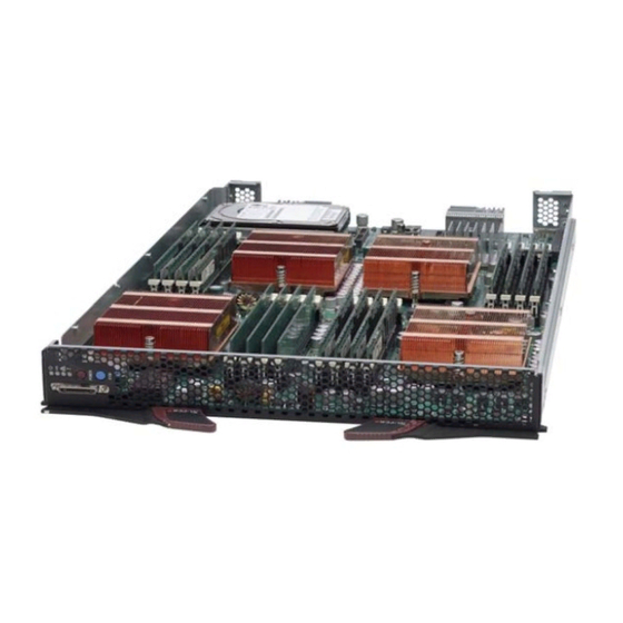
Short the CMOS pads with a metal object such as a small screwdriver. 3. Replace the cover, install the blade back into the enclosure and power it on. Blade Unit Components Figure 4-5. Exploded View of SBA-7141M-T Blade Module... -
Page 37: Memory Support
(128-bit) memory, which is faster than non-interleaved (64-bit) memory. Section 3-5 for further details on mainboard memory installation. Hard Disk Drives The SBA-7141M-T blade unit can accommodate one internal 2.5" SATA hard disk drive, which is mounted directly on the blade’s mainboard. - Page 38 SBA-7141M-T Blade Module User’s Manual Notes...
-
Page 39: Chapter 5 Bios
Chapter 5 BIOS Introduction This document describes the AMI BIOS™ Setup utility for the SBA-7141M-T AMD Blade Module. The AMI ROM BIOS is stored in a flash chip and can be easily upgraded using a floppy disk-based program. NOTE: Due to periodic changes to the BIOS, some settings may have been added or deleted and might not yet be recorded in this manual. -
Page 40: Bios Updates
SBA-7141M-T Blade Module User’s Manual BIOS Updates It may be necessary to update the BIOS used in the blade modules on occasion. However, it is recommended that you not update BIOS if you are not experiencing problems with a blade module. -
Page 41: Running Setup
Chapter 5: BIOS Flashing a BIOS using a Floppy Image File NOTE: This method must be performed remotely. 1. Copy the image file from the zip file to your desktop. 2. Use the web browser or IPMIView to access your CMM remotely using its IP Address. -
Page 42: Main Bios Setup Menu
Often a text message will accompany it. NOTE: The BIOS has default text messages built in. SuperMicro retains the option to include, omit, or change any of these text messages. -
Page 43: Advanced Settings Menu
Chapter 5: BIOS Advanced Settings Menu Choose Advanced from the BIOS Setup Utility main menu with the arrow keys. The items with a triangle beside them have sub menus that can be accessed by highlighting the item and pressing <E >. - Page 44 SBA-7141M-T Blade Module User’s Manual Table 5-1. BOOT Settings Configuration Submenu (Continued) Menu Option Description Change this setting if using a 64-bit Linux operating system. The available OS Installation options are Other and L INUX ACPI Configuration ACPI Version Use this setting the determine which ACPI version to use. Options are ACPI Features v1.0, ACPI...
-
Page 45: Cpu Configuration
Chapter 5: BIOS CPU Configuration The menu options in the CPU C submenu and their descriptions are ONFIGURATION shown in Table 5-2. Table 5-2. CPU Configuration Submenu Menu Option Description GART Error This setting is used to Enable or Disable GART error processing. Reporting Microcode Update This setting is used to Enable or D... -
Page 46: Pci/Pnp Configuration
SBA-7141M-T Blade Module User’s Manual PCI/PnP Configuration The menu options in the PCI/P submenu and their descriptions are ONFIGURATION shown in Table 5-4. Table 5-4. PCI/PnP Configuration Submenu Menu Option Description Clear NVRAM Select Y to clear NVRAM during boot-up. The options are Y and No. -
Page 47: Super Io Configuration
Chapter 5: BIOS Super IO Configuration The menu options in the S IO C submenu and their descriptions are UPER ONFIGURATION shown in Table 5-5. Table 5-5. Super IO Configuration Submenu Menu Option Description This option specifies the base I/O port address and Interrupt Request address of serial port 1. -
Page 48: Northbridge Configuration
SBA-7141M-T Blade Module User’s Manual NorthBridge Configuration The menu options in the N submenu and their descriptions ORTH RIDGE ONFIGURATION are shown in Table 5-7. Table 5-7. NorthBridge Configuration Submenu Menu Option Description Memory Configuration Select Auto to automatically enable interleaving-memory scheme when this Bank Interleaving function is supported by the processor. -
Page 49: Southbridge/Mcp55 Configuration
Chapter 5: BIOS SouthBridge/MCP55 Configuration The menu options in the S /MCP55 C submenu and their OUTH RIDGE ONFIGURATION descriptions are shown in Table 5-8. Table 5-8. SouthBridge/MCP55 Configuration Submenu Menu Option Description CPU/LDT Spread Enables spread spectrum for the CPU/LDT. Options are Center Spread, D Spectrum or D PREAD... -
Page 50: Event Log Configuration
SBA-7141M-T Blade Module User’s Manual Event Log Configuration The menu options in the E submenu and their descriptions are VENT ONFIGURATION shown in Table 5-9. Table 5-9. Event Log Configuration Submenu Menu Option Description View Event Log Highlight this item and press <E >... -
Page 51: Remote Access Configuration
Chapter 5: BIOS Remote Access Configuration The menu options in the R submenu and their EMOTE CCESS ONFIGURATION descriptions are shown in Table 5-11. Table 5-11. Remote Access Configuration Submenu Menu Option Description Allows you to E or Disable remote access. If enabled, the settings below NABLE Remote Access will appear. -
Page 52: Boot Menu
SBA-7141M-T Blade Module User’s Manual Boot Menu The menu options for the B menu are shown in Table 5-13. Table 5-13. Boot menu Menu Option Description This feature allows the user to prioritize the boot sequence from the available devices. The devices to set are: •... -
Page 53: Exit Menu
Chapter 5: BIOS Exit Menu Select the E tab from AMI BIOS S screen to enter the E BIOS S ETUP TILITY ETUP screen. The options for the E menu are shown in Table 5-15. You may also additionally press <E >... - Page 54 SBA-7141M-T Blade Module User’s Manual Notes 5-16...
-
Page 55: Appendix Abios Post Codes
Appendix A BIOS POST Codes BIOS POST Messages During the Power-On Self-Test (POST), the BIOS will check for problems. If a problem is found, the BIOS will activate an alarm or display a message. The following is a list of such BIOS messages. - Page 56 SBA-7141M-T Blade Module User’s Manual Table A-1. BIOS POST Messages (Continued) BIOS Message Description Previous POST did not complete successfully. POST loads default values and offers to run Setup. If the failure was caused by incorrect values and they are not corrected, the next boot Previous boot incomplete - Default will likely fail.
-
Page 57: A-2 Bios Post Codes
Table A-1. BIOS POST Messages (Continued) BIOS Message Description Where nnnn is the amount of RAM in kilobytes successfully nnnn kB Extended RAM Passed tested. Where nnnn is the amount of system cache in kilobytes nnnn Cache SRAM Passed successfully tested. Where nnnn is the amount of shadow RAM in kilobytes nnnn kB Shadow RAM Passed successfully tested. -
Page 58: Recoverable Post Errors
SBA-7141M-T Blade Module User’s Manual Recoverable POST Errors When a recoverable type of error occurs during POST, the BIOS will display an POST code that describes the problem. BIOS may also issue one of the following beep codes: • One long and two short beeps – video configuration error •... - Page 59 Table A-2. Terminal POST Errors (Continued) Post Code Description 1-3-1-3 Test 8742 Keyboard Controller Auto size DRAM Initialize POST Memory Manager Clear 512 kB base RAM 1-3-4-1 RAM failure on address line xxxx* 1-3-4-3 RAM failure on data bits xxxx* of low byte of memory bus Enable cache before system BIOS shadow Test CPU bus-clock frequency Initialize Phoenix Dispatch Manager...
- Page 60 SBA-7141M-T Blade Module User’s Manual Table A-2. Terminal POST Errors (Continued) Post Code Description Test RAM between 512 and 640 kB Test extended memory Test extended memory address lines Jump to UserPatch1 Configure advanced cache registers Initialize Multi Processor APIC...
- Page 61 Table A-2. Terminal POST Errors (Continued) Post Code Description Build MPTABLE for multi-processor boards Install CD ROM for boot Clear huge ES segment register 1-2 Search for option ROMs. One long, two short beeps on check-sum failure Check for SMART Drive (optional) Shadow option ROMs Set up Power Management Initialize security engine (optional)
-
Page 62: Table A-3. Boot Block Flash Rom Terminal Post Errors
SBA-7141M-T Blade Module User’s Manual Table A-2. Terminal POST Errors (Continued) Post Code Description Initialize system error handler PnPnd dual CMOS (optional) Initialize note dock (optional) Initialize note dock late Force check (optional) Extended checksum (optional) Redirect Int 15h to enable remote keyboard... - Page 63 Table A-3. Boot Block Flash ROM Terminal POST Errors (Continued) Post Code Description Initialize video Initialize System Management Manager Output one beep Clear Huge Segment Boot to Mini DOS Boot to Full DOS If the BIOS detects error 2C, 2E, or 30 (base 512K RAM error), it displays an additional word-bitmap ( ) indicating the address line or bits that failed.
- Page 64 SBA-7141M-T Blade Module User’s Manual Notes A-10...
- Page 65 Disclaimer The products sold by Supermicro are not intended for and will not be used in life support systems, medical equipment, nuclear facilities or systems, aircraft, aircraft devices, aircraft/emergency communication devices or other critical systems whose failure to perform be reasonably expected to result in significant injury or loss of life or catastrophic property damage.
- Page 66 SBA-7141M-T Blade Module User’s Manual...
Need help?
Do you have a question about the SBA-7141M-T and is the answer not in the manual?
Questions and answers