Sennheiser Digital 6000 Instruction Manual
Hide thumbs
Also See for Digital 6000:
- Instruction manual (111 pages) ,
- Quick manual (2 pages) ,
- Quick manual (2 pages)

Related Manuals for Sennheiser Digital 6000


Summary of Contents for Sennheiser Digital 6000
- Page 1 Digital 6000 Instruction manual Sennheiser electronic GmbH & Co. KG Am Labor 1, 30900 Wedemark, Germany, www.sennheiser.com Digital 6000 - v1.5...
-
Page 2: Table Of Contents
The Digital 6000 Series 6 Features 7 Products in the Digital 6000 series 8 EM 6000 | EM 6000 DANTE 2-channel receiver 9 Package contents 9 Product overview 10 SKM 6000 handheld transmitter 11 Package contents 11 Product overview 12... - Page 3 Installing the LM 6060 and LM 6061 charging modules in the L 6000 57 Installing the L 6000 in a rack 59 Using Digital 6000 series devices 60 Using the EM 6000 61 Operating elements on the front of the device 62...
- Page 4 Step 2: Editing displayed frequencies 89 Step 3: Starting the automatic frequency setup 91 Walktest menu item 92 AF Output menu item 94 Test Tone menu item 95 Bank Edit menu item 97 System menu item 99 Wordclock 100 Network 101 Device ID 103 Dante Settings (only EM 6000 DANTE) 104 Booster Feed 107...
- Page 5 LM 6060 and LM 6061 status LEDs 137 LM 6060 and LM 6061 status LEDs in storage mode Preparing rechargeable batteries for storage (storage mode) 138 Meaning of the status LEDs in storage mode 138 Resetting settings (factory reset) 139 Updating the firmware 140 Operating the L 6000 via a network 141 Establishing a radio link 142...
- Page 6 Cleaning and maintenance 168 Cleaning the sound inlet basket of the microphone mo- dule 168 Cleaning the SK 6000 bodypack transmitter contacts. Cleaning the L 6000 charger 169...
-
Page 7: The Digital 6000 Series
The 6000 series includes a 2-channel receiver, a bodypack transmitter, a handheld transmitter and a modular 19-inch rack-mounted charger. Digital 6000 combines the benefits of modern audio technology with an in- telligent operating concept. The frequency range can be scanned directly with the receiver, which then distributes free frequencies within the net- work. -
Page 8: Features
The Dante version with an Audinate Brooklyn II card offers an additional Amphenol RJ-45 jack plug for integrating the receiver into a Dante net- work. The Digital 6000 series includes a 2-channel receiver available in 2 ver- sions, a bodypack transmitter, a handheld transmitter and a modular 19- inch rack-mounted charger. -
Page 9: Products In The Digital 6000 Series
Products in the Digital 6000 series Products in the Digital 6000 series ► Click the name of the particular product to learn more about it. You can also find more information here: •A variety of frequency variants are available from the SKM 6000 and SK 6000. -
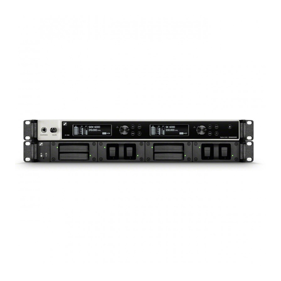
Page 10: Em 6000 | Em 6000 Dante 2-Channel Receiver
Products in the Digital 6000 series EM 6000 | EM 6000 DANTE 2-channel receiver ► The digital 2-channel receiver works via a switching bandwidth of 244 MHz (470 to 714 MHz) that is covered by three transmitter versions (470 to 558 MHz, 550 to 638 MHz and 630 to 718 MHz). -
Page 11: Product Overview
Products in the Digital 6000 series Product overview View of the front side: ► Rear view of the EM 6000: ► Rear view of the EM 6000 DANTE: ►... -
Page 12: Skm 6000 Handheld Transmitter
Products in the Digital 6000 series SKM 6000 handheld transmitter ► A variety of frequency variants are available from the SKM 6000 handheld transmitter. You can find more information under “SKM 6000 product vari- ants”. For more detailed information about installing and operating the SKM 6000 handheld transmitter, see “Installing the SKM 6000”... -
Page 13: Product Overview
Products in the Digital 6000 series Product overview View of the front side: ► View of the rear side with the display: ►... -
Page 14: Sk 6000 Bodypack Transmitter
Products in the Digital 6000 series SK 6000 bodypack transmitter ► A variety of frequency variants are available from the SK 6000 bodypack transmitter. You can find more information under “SK 6000 product vari- ants”. For more detailed information about installing and operating the SK 6000 bodypack transmitter, see “Installing the SK 6000”... -
Page 15: Product Overview
Products in the Digital 6000 series Product overview View of the front side: ► View without rechargeable battery: ►... -
Page 16: Modular L 6000 Charger
Products in the Digital 6000 series Modular L 6000 charger ► The L 6000 charger is used to charge the BA 60 and BA 61 rechargeable batteries. The 2 charging modules LM 6060 (for the BA 60) and LM 6061 (for the BA 61) are required to do so. -
Page 17: Product Overview
Products in the Digital 6000 series Product overview View with the charging modules and rechargeable batteries inserted: ► View with the LM 6060 charging modules without rechargeable batter- ies inserted: ► View with the LM 6061 charging modules without rechargeable batter- ies inserted: ►... -
Page 18: Accessories
Accessories Accessories Various accessory parts are available for the Digital 6000 series. Charging modules for L 6000 charger LM 6060 The LM 6060 charging module is installed in the L 6000 charger to charge the BA 60 rechargeable battery. 4 Torx 10 screws for mounting in the L 6000 are included in the delivery. -
Page 19: Rechargeable Batteries And Battery Compartments
NiMh rechargeable batteries. In addition, the remaining battery life of the transmitters can be read to the exact minute on the transmitter and receiver. These rechargeable batteries must be charged only with Sennheiser L 6000 and L 60 chargers. Battery compartments:... -
Page 20: Ba 60 Rechargeable Battery
BA 60 rechargeable battery The BA 60 rechargeable battery is intended to operate the SKM 6000 handheld transmitter. ► Sennheiser article number 504702 B 60 battery compartment The B 60 battery compartment is intended to operate the SKM 6000 hand- held transmitter. -
Page 21: Ba 61 Rechargeable Battery
BA 61 rechargeable battery The BA 61 rechargeable battery is intended to operate the SK 6000 bodypack transmitter. ► Sennheiser article number 504703 B 61 battery compartment The B 61 battery compartment is intended to operate the SK 6000 bodypack transmitter. -
Page 22: Microphones And Cables
You can also use microphone modules from the evolution wireless G3 and 2000 series with the SKM 6000 handheld transmitter. You can find more information about the individual microphone modules on their respective product pages at www.sennheiser.com or www.neu- mann.com. -
Page 23: Headset And Lavalier Microphones
SL Headmic 1-4 Headset microphone, omni-directional 506905 You can find more information about the individual microphones on their respective product pages at www.sennheiser.com. Line/instrument cables The following cable is available to connect instruments and line sources to the SK 6000 bodypack transmitter: •... -
Page 24: Antennas And Accessories
Accessories Antennas and accessories The following antenna components are available as accessory parts. Omni-directional antennas • A 1031-U, passive omni-directional antenna, article no. 004645 • A 3700, active omni-directional antenna, article no. 502195 Directional antennas • A 2003 UHF, passive directional antenna, article no. 003658 •... -
Page 25: Installing Digital 6000 Series Devices
Installing Digital 6000 series devices Installing Digital 6000 series devices You can find information about installing and connecting Digital 6000 se- ries devices in the following sections. • EM 6000 2-channel receiver >> “Installing the EM 6000” • SKM 6000 handheld transmitter >> “Installing the SKM 6000”... -
Page 26: Installing The Em 6000
Installing the EM 6000 Installing the EM 6000 These sections contain detailed information about installing the EM 6000. You can find information about operating the EM 6000 under “Using the EM 6000”. -
Page 27: Connectors On The Rear Of The Device
Installing the EM 6000 Connectors on the rear of the device Product overview for the rear side of the EM 6000 ► Power socket • See “Connecting/disconnecting the EM 6000 to/from the power supply system” Ethernet socket for controlling the device via the network and Sennhe- iser WSM •... -
Page 28: Em 6000 Dan
Installing the EM 6000 Product overview for the rear side of the EM 6000 DANTE ► Power socket • See “Connecting/disconnecting the EM 6000 to/from the power supply system” The Dante™ interface • See “Outputting audio via a Dante™ network (EM 6000 DANTE only)” Ethernet socket for controlling the device via the network and Sennhe- iser WSM •... -
Page 29: Connecting/Disconnecting The Em 6000 To/From The Power Supply System
Installing the EM 6000 Connecting/disconnecting the EM 6000 to/from the power supply system To connect the EM 6000 to the power supply system: ▷ Connect the mains cable IEC connector to the power socket on the rear side of the EM 6000. ▷... -
Page 30: Connecting The Em 6000 To A Network
Ethernet socket on the rear side of the EM 6000. ► For more information about controlling devices via the Sennheiser Wireless Systems Manager (WSM) software, refer to the instruction manual for the software. You can download the software at... -
Page 31: Outputting Analog Audio Signals
Installing the EM 6000 Outputting analog audio signals Each of the two channels CH 1 and CH 2 on the EM 6000 have both a sym- metrical XLR-3M output socket and a symmetrical 6.3 mm (1/4") jack out- put socket. Always use only one of the two Bal AF out output sockets for each ▷... -
Page 32: Outputting Digital Audio Signals
Installing the EM 6000 Outputting digital audio signals The EM 6000 can also output digital audio. To do so, use the Digital Audio AES 3 output on the rear side of the EM 6000. The Digital Audio AES 3 output socket is designed as an XLR-3M socket. -
Page 33: Outputting Audio Via A Dante™ Network (Em 6000 Dante Only)
Installing the EM 6000 Outputting audio via a Dante™ network (EM 6000 DANTE only) The EM 6000 DANTE has a Dante interface (Audinate Brooklyn II) for out- putting digital audio signals via a Dante™ network. Connect a Dante-enabled network cable to the Dante socket on the ▷... -
Page 34: Connecting The Word Clock
Installing the EM 6000 Connecting the word clock You can use the internal word clock on the EM 6000 or connect an external word clock. You can also output the external word clock and cascade it up to 16 receiv- ers. - Page 35 Installing the EM 6000 To cascade the word clock: Connect the Wordclock In input of the next EM 6000 to the Wordclock ▷ Out output of the previous EM 6000. ►...
-
Page 36: Connecting Remote Antennas
Installing the EM 6000 Connecting remote antennas We recommend using remote antennas. You can also find useful informa- tion about using antennas under “Recommendations for using antennas”. To connect remote antennas: ▷ Connect the first antenna to the RF in socket for Antenna A on the rear side of the EM 6000. -
Page 37: Cascading Receivers
Installing the EM 6000 Cascading receivers For larger 4-channel systems, you can cascade up to 8 receivers without using additional antenna splitters and you then require only one pair of an- tennas. ►... -
Page 38: Connecting Rod Antennas
Installing the EM 6000 Connecting rod antennas We recommend using remote antennas. You can also find useful informa- tion about using antennas under “Recommendations for using antennas”. To connect the supplied rod antennas: ▷ Connect the first rod antenna to the RF in socket for Antenna A on the rear side of the EM 6000. -
Page 39: Installing The Em 6000 In A Rack
Installing the EM 6000 Installing the EM 6000 in a rack You can install the EM 6000 2-channel receiver in any conventional 19" rack. The rack mounting angles are already attached to the device. Always observe the following information during rack mounting. Support the EM 6000 after installation in the rack. -
Page 40: Installing The Skm 6000
Installing the SKM 6000 Installing the SKM 6000 These sections contain detailed information about installing the SKM 6000. You can find information about operating the SKM 6000 under “Using the SKM 6000”. -
Page 41: Inserting And Removing The Ba 60 Rechargeable Battery
Installing the SKM 6000 Inserting and removing the BA 60 rechargeable bat- tery We recommend using the BA 60 rechargeable battery instead of the B 60 battery compartment. You can find more information about this subject under “Rechargeable batteries and battery compartments”. Charge the BA 60 rechargeable battery before using it for the first time. - Page 42 Installing the SKM 6000 To remove the BA 60 rechargeable battery from the SKM 6000 handheld transmitter: ▷ Press the two catches as shown in the figure and pull the BA 60 re- chargeable battery out of the SKM 6000 handheld transmitter. ►...
-
Page 43: Inserting And Removing The B 60 Battery Compartment
Installing the SKM 6000 Inserting and removing the B 60 battery compart- ment We recommend using the BA 60 rechargeable battery instead of the B 60 battery compartment. You can find more information about this subject under “Rechargeable batteries and battery compartments”. Before using the battery compartment, you must insert the batteries as shown in the figure. - Page 44 Installing the SKM 6000 To remove the B 60 battery compartment from the SKM 6000 handheld transmitter: ▷ Press the two catches as shown in the figure and pull the B 60 battery compartment out of the SKM 6000 handheld transmitter. ►...
-
Page 45: Replacing The Microphone Module
Installing the SKM 6000 Replacing the microphone module We recommend using the following microphone modules with the SKM 6000 handheld transmitter. ► Module Features Article no. MMD 835-1 BK Dynamic, cardioid, black 502575 MMD 845-1 BK Dynamic, super-cardioid, black 502576 MMD 865-1 BK Capacitor, super-cardioid, black 502581... - Page 46 Installing the SKM 6000 To change the microphone module: Screw or unscrew the microphone module onto or from the handheld ▷ transmitter as shown in the figure. ► With some microphone modules, the upper part of the microphone basket can be screwed off. Ensure that you always completely un- screw the microphone module.
-
Page 47: Installing The Sk 6000
Installing the SK 6000 Installing the SK 6000 These sections contain detailed information about installing the SK 6000. You can find information about operating the SK 6000 under “Using the SK 6000”. -
Page 48: Inserting And Removing The Ba 61 Rechargeable Battery
Installing the SK 6000 Inserting and removing the BA 61 rechargeable bat- tery We recommend using the BA 61 rechargeable battery instead of the B 61 battery compartment. You can find more information about this subject under “Rechargeable batteries and battery compartments”. Charge the BA 61 rechargeable battery before using it for the first time. - Page 49 Installing the SK 6000 To remove the BA 61 rechargeable battery from the SK 6000 bodypack transmitter: ▷ Press the two catches as shown in the figure and pull the BA 61 re- chargeable battery out of the SK 6000 bodypack transmitter. ►...
-
Page 50: Inserting And Removing The B 61 Battery Compartment
Installing the SK 6000 Inserting and removing the B 61 battery compart- ment We recommend using the BA 61 rechargeable battery instead of the B 61 battery compartment. You can find more information about this subject under “Rechargeable batteries and battery compartments”. Before using the battery compartment, you must insert the batteries as shown in the figure. - Page 51 Installing the SK 6000 To remove the B 61 battery compartment from the SK 6000 bodypack transmitter: ▷ Press the two catches as shown in the figure and pull the B 61 battery compartment out of the SK 6000 bodypack transmitter. ►...
-
Page 52: Mounting The Antenna
Installing the SK 6000 Mounting the antenna To mount the supplied antenna: ▷ Connect the antenna to the SK 6000 bodypack transmitter antenna socket as shown in the figure. Tightly screw on the antenna coupling ring on the SK 6000 bodypack ▷... -
Page 53: Connecting A Microphone To The Sk 6000
SK 6000 bodypack transmitter. ► For more information about using the particular microphone, see the corresponding instruction manual for the microphone. You can find this instruction manual in the download section of the Sennheiser website under www.sennheiser.com/download. -
Page 54: Connecting An Instrument Or Line Source To The Sk 6000
You can connect instruments or audio sources with a line level to the SK 6000 bodypack transmitter. To do so, you require the Sennheiser CI 1-4 cable (6.3 mm (1/4") jack plug to 3-pin audio connector) To connect an instrument or line source to bodypack transmitter: ▷... -
Page 55: Installing The L 6000 | Lm 6060 | Lm 6061
Installing the L 6000 | LM 6060 | LM 6061 Installing the L 6000 | LM 6060 | LM 6061 These sections contain detailed information about installing the L 6000. You can find information about operating the L 6000 under “Using the L 6000”. -
Page 56: Connecting/Disconnecting The L 6000 To/From The Power Supply System
Installing the L 6000 | LM 6060 | LM 6061 Connecting/disconnecting the L 6000 to/from the power supply system To connect the L 6000 to the power supply system: ▷ Connect the mains cable IEC connector to the power socket on the rear side of the L 6000. -
Page 57: Connecting The L 6000 To A Network
Connect a network cable with an RJ-45 connector (Cat5 at minimum) to the Ethernet socket on the rear side of the L 6000. ► For more information about controlling devices via the Sennheiser Wireless Systems Manager (WSM) software, refer to the instruction manual for the software. -
Page 58: Installing The Lm 6060 And Lm 6061 Charging Modules In The L 6000
Installing the L 6000 | LM 6060 | LM 6061 Installing the LM 6060 and LM 6061 charging mod- ules in the L 6000 The following two charging modules are available for the L 6000 charger: • LM 6060 -> for charging the BA 60 rechargeable battery ►... - Page 59 Fully slide the charging module into the open charging slot as shown in ▷ the figure. The charging module can be inserted into the L 6000 housing only in one direction. The Sennheiser lettering on the charging module must face upward. ► Tightly screw on the charging module.
-
Page 60: Installing The L 6000 In A Rack
Installing the L 6000 | LM 6060 | LM 6061 Installing the L 6000 in a rack You can install the L 6000 charger in any conventional 19" rack. The rack mounting angles are already attached to the device. Always observe the following information during rack mounting. Support the L 6000 charger after installation in the rack. -
Page 61: Using Digital 6000 Series Devices
Using Digital 6000 series devices Using Digital 6000 series devices You can find information about using Digital 6000 series devices in the following sections. • EM 6000 2-channel receiver >> “Using the EM 6000” • SKM 6000 handheld transmitter >> “Using the SKM 6000”... -
Page 62: Using The Em 6000
Using the EM 6000 Using the EM 6000 These sections contain detailed information about operating the EM 6000. You can find information about installing the EM 6000 under “Installing the EM 6000”. -
Page 63: Operating Elements On The Front Of The Device
Using the EM 6000 Operating elements on the front of the device Product overview for the front of the EM 6000 ► Displaying and using channel 1 (CH 1) • See “Displays on the EM 6000 display panel” • See “Buttons for navigating through the menu” Displaying and using channel 2 (CH 2) •... - Page 64 Using the EM 6000 Warning indicator for error messages (separate for CH 1 and CH 2) • See “Status messages” 10Display (separate for CH 1 and CH 2) • See “Displays on the EM 6000 display panel” 11Infra-red interface for the SYNC function •...
-
Page 65: Switching The Em 6000 On And Off
See “Connecting/disconnecting the EM 6000 to/from the power sup- ply system”. ▷ Short-press the On/Off button. The Sennheiser logo is temporarily displayed on the two displays. The two displays then show the home screen for the relevant channel. To switch off the EM 6000: ▷... -
Page 66: Displays On The Em 6000 Display Panel
Using the EM 6000 Displays on the EM 6000 display panel The EM 6000 has a separate display for each of the two channels CH 1 and CH 2. • In the displays, the home screens for both channels display the chan- nel-specific status information such as the reception quality, battery life, audio level, and so on. -
Page 67: Buttons For Navigating Through The Menu
Using the EM 6000 Buttons for navigating through the menu To navigate through the EM 6000 operating menu, you require the follow- ing buttons. ► NEXT Turn the jog dial to the right: • Display the next home screen • Scroll down in the menu PREVIOUS Turn the jog dial to the left: •... -
Page 68: Home Screen
Using the EM 6000 Home screen After you switch on the receiver, the two displays initially show the Senn- heiser logo. After a short time, the home screen is then displayed. ► The home screen has 4 different views in total, which display different sta- tus information. -
Page 69: Home Screen 1
Using the EM 6000 Home screen 1 ► The first home screen that is displayed as the initial view after the device switches on contains the following status information. ► Display on the display Meaning panel RF = Radio Frequency Display of the radio link RF level for antenna A and antenna B. - Page 70 Using the EM 6000 Remaining battery life Shows the remaining battery life and the transmitter operating time. The time is displayed only if the BA 60 and BA 61 rechargeable batteries are used. For normal batteries, only the charge level of the batteries is displayed without time infor- mation.
-
Page 71: Home Screen 2
Using the EM 6000 Home screen 2 ► The second home screen contains the following status information about the receiver settings. ► Display on the display Meaning panel Bank/Channel Shows which channel is set in which fre- quency bank. See “Frequency menu item”. AF Out Shows the receiver audio output level that is output via the audio outputs. -
Page 72: Home Screen 3
Using the EM 6000 Home screen 3 ► The third home screen contains the following status information about the transmitter settings. ► Display on the display Meaning panel Capsule Shows the microphone module with which the handheld transmitter is equipped. Recommended microphone modules for the handheld transmitter: “Microphone mod- ules”... -
Page 73: Home Screen 4
Using the EM 6000 Home screen 4 ► The fourth home screen contains the following status information about the receiver network settings. ► Display on the display Meaning panel IP Mode Shows whether the IP address is assigned automatically or manually. See “Network” under “System menu item”. -
Page 74: Setting Options In The Menu
Using the EM 6000 Setting options in the menu In the EM 6000 menu, you can configure the following settings. ► Adjusting frequencies See “Frequency menu item” ▷ Setting up user-defined frequency banks ▷ See “Bank Edit menu item” Changing link names See “Name menu item”... -
Page 75: Menu Structure
Using the EM 6000 Menu structure The figure shows the complete EM 6000 menu structure in an overview. ►... -
Page 76: Frequency Menu Item
Using the EM 6000 Frequency menu item In the Frequency menu item, you can adjust the frequency for the channel in question. You can select a frequency from the predefined frequency banks B1 to B6 (up to 65 channels per bank) or manually adjust the frequency. You can also select frequencies from the user-defined frequency banks U1 to U6. - Page 77 Using the EM 6000 ► ▷ Turn the jog dial to set a different channel. Press the SAVE button to confirm the selection of the bank and chan- ▷ nel. ▷ Press the jog dial to go to the manual frequency setting: ►...
-
Page 78: Name Menu Item
Using the EM 6000 Name menu item In the Name menu item, you can define the name of the link for the channel in question. This name is the name of the radio link between the transmitter and receiver. In the network settings, you can enter the receiver name as it is displayed in a network: see “Device ID”... -
Page 79: Sync Settings Menu Item
Using the EM 6000 Sync Settings menu item In the Sync Settings menu item, you can choose which settings for the transmitter you want to transfer from the receiver to the transmitter during the synchronization. All of the settings can also be set separately in the menu on the transmitter. However, you can simply use the Sync function to configure these settings via the receiver. - Page 80 Using the EM 6000 To open the Sync Settings menu item: On the home screen, press the jog dial to open the operating menu. ▷ ▷ Turn the jog dial until the Sync Settings menu item appears in the se- lection frame: ►...
-
Page 81: Gain
Using the EM 6000 You can perform the following actions: Press the jog dial to choose between the following options: ▷ ► Switch between the options Set the Set value Turn the jog dial to choose be- Turn the jog dial to set the de- ▷... -
Page 82: Low Cut
Using the EM 6000 Low Cut Adjusting the low cut filter for the transmitter ► You can configure the following settings for the Set value: • 30 Hz to 120 Hz in increments of 30 Hz. • no sync, so that this value is not synchronized Auto Lock ►... -
Page 83: Display Panel
Using the EM 6000 Display panel ► You can configure the following settings for the Set value: • Name, Frequency, or Preset • no sync, so that this value is not synchronized Cable ► The Cable function is a cable emulator that you can in 3 stages (Type 1, Type 2, and Type 3). -
Page 84: Encryption Menu Item
Using the EM 6000 Encryption menu item You can secure the radio link between the transmitter and receiver using AES 256 encryption. To open the Encryption menu item: On the home screen, press the jog dial to open the operating menu. ▷... - Page 85 Using the EM 6000 ▷ Set the desired value. Press the SAVE button to save your selection. ▷ If you have activated encryption, you must first transfer this setting to the transmitter using the Sync function. See “Synchronizing devices”. Encryption cannot be activated on the transmitter itself.
-
Page 86: Scan & Auto-Setup Menu Item
E, which is provided to do so. For more in- formation about the equidistant frequency grid, see “Equidistant frequency grid”. Alternatively, you can use the Sennheiser Wireless Systems Manager (WSM) software. Performing a frequency scan and automatic frequency setup... - Page 87 Using the EM 6000 To open the Scan & Auto-Setup menu item: On the home screen, press the jog dial to open the operating menu. ▷ ▷ Turn the jog dial until the Scan & Auto-Setup menu item appears in the selection frame: ►...
-
Page 88: Step 1A: New Scan
Using the EM 6000 Step 1a: New Scan After you choose New Scan, the following view is displayed. ► ▷ Turn the jog dial to select the frequency range to be scanned: • Choose All for the Country setting to scan the entire EM 6000 fre- quency range. -
Page 89: Step 1B: Use Old Scan
Using the EM 6000 ▷ After you set the frequency range to be scanned, press the jog dial until the Start option in the top left of the selection is displayed with a white background. ► ▷ Press the jog dial to start the frequency scan. The scan is performed. -
Page 90: Step 2: Editing Displayed Frequencies
Using the EM 6000 If you choose the Use Old Scan option, the result of the last scan is dis- played. ► ▷ Turn the jog dial to scroll through the frequency banks and display the number of free frequencies available for each bank. The frequency bank that you select here is used for the automatic fre- quency setup in step 3. - Page 91 Using the EM 6000 ► ▷ Press the jog dial to search for the channel that you want to skip during the automatic frequency setup. ▷ Press the jog dial The checkbox for the Skip option is highlighted in white. ▷...
-
Page 92: Step 3: Starting The Automatic Frequency Setup
Using the EM 6000 Step 3: Starting the automatic frequency setup If you have performed the scan and edited the frequencies, you can start the automatic frequency setup. ► On the display, the Party option must be highlighted in white. ▷... -
Page 93: Walktest Menu Item
Using the EM 6000 Walktest menu item Once you have set up and installed all of the receivers and transmitters for your event, we recommend performing a walk test. This lets you check whether sufficient reception strength is available throughout the entire area used. - Page 94 Using the EM 6000 The following values are recorded on the display: ► RF A Reception from antenna A in dBm RF B Reception from antenna B in dBm Connection quality as a % See also “Meaning of the Link Quality Indicator” Transmitter audio frequency in dBFS ►...
-
Page 95: Af Output Menu Item
Using the EM 6000 AF Output menu item In the AF Output menu item, you can set the audio level that is output via the receiver audio outputs. To open the AF Output menu item: On the home screen, press the jog dial to open the operating menu. ▷... -
Page 96: Test Tone Menu Item
Using the EM 6000 Test Tone menu item The EM 6000 provides an option for generating a test tone. You can use it, for example, to check the audio output of the device or level out channels on the mixing console. To open the Test Tone menu item: ▷... - Page 97 Using the EM 6000 ► While the test tone is played back, the transmitter audio signal is muted.
-
Page 98: Bank Edit Menu Item
Using the EM 6000 Bank Edit menu item In addition to the predefined frequency banks B1 to B6, you can assign fre- quencies to the user-defined frequency banks U1 to U6 yourself. To open the Bank Edit menu item: On the home screen, press the jog dial to open the operating menu. ▷... - Page 99 Using the EM 6000 ► ▷ Turn the jog dial to select the desired channel (from 00 to 99). Press the jog dial to switch to the frequency selection. ▷ ► ▷ Turn the jog dial to set the desired frequency for the selected bank and selected channel.
-
Page 100: System Menu Item
Using the EM 6000 System menu item In the System menu item, you can configure all of the cross-system set- tings. The System menu item is located in the menu of the channel CH 1. To open the System menu item: On the home screen, press the jog dial to open the operating menu. -
Page 101: Wordclock
Using the EM 6000 Wordclock In this menu item, you can configure the settings for the word clock. To open the Wordclock menu item: ▷ Turn the jog dial in the System menu item until the Wordclock menu item appears in the selection frame. Press the jog dial to open the menu. -
Page 102: Network
Using the EM 6000 Network In this menu item, you can configure the settings for the network connec- tion. To open the Network menu item: ▷ Turn the jog dial in the System menu item until the Network menu item appears in the selection frame. - Page 103 Using the EM 6000 ► To configure the settings in IP Mode Manual and IP Mode mDNS: Press the jog dial to switch between the individual network configura- ▷ tion items. Turn the jog dial to set the value. ▷ ►...
-
Page 104: Device Id
Using the EM 6000 Device ID You can enter the name of the device in this menu item. This name is dis- played for this EM 6000 in the network. To open the Device ID menu item: ▷ Turn the jog dial in the System menu item until the Device ID menu item appears in the selection frame. -
Page 105: Dante Settings (Only Em 6000 Dante)
Using the EM 6000 Dante Settings (only EM 6000 DANTE) In this menu item, you can configure the network settings for the Dante™ network. This menu item is available only with the product version EM 6000 DANTE. To open the Dante Settings menu item: Turn the jog dial in the System menu item until the Dante Settings ▷... - Page 106 Using the EM 6000 Network Turn the jog dial to choose between the two IP assignment modes Auto ▷ and Manual. ► ► To configure the settings in IP Mode Manual: ▷ Press the jog dial to switch between the individual network configura- tion items.
- Page 107 Using the EM 6000 Info This menu item shows the MAC address of the Dante™ interface and the current version of the Dante™ firmware. You cannot configure any settings here. ► You can find information about updating the Dante™ firmware under “Updating the firmware of the Dante™...
-
Page 108: Booster Feed
Using the EM 6000 Booster Feed In this menu item, you can activate the power supply for an external anten- na amplifier if you are using active remote antennas. You can find more information about antennas under “Recommenda- tions for using antennas”. To open the Booster Feed menu item: Turn the jog dial in the System menu item until the Booster Feed menu ▷... -
Page 109: Brightness
Using the EM 6000 Brightness In this menu item, you can set the brightness of the display. The set bright- ness applies to both EM 6000 displays. To open the Brightness menu item: ▷ Turn the jog dial in the System menu item until the Brightness menu item appears in the selection frame. -
Page 110: Auto Setup
Using the EM 6000 Auto Setup In this menu item, you can activate the auto setup function for the EM 6000. If the function is activated here, an automatic frequency setup can be performed for this EM 6000. See “Scan & Auto-Setup menu item”. To open the Auto Setup menu item: ▷... -
Page 111: Info
Using the EM 6000 Info This menu item shows the MAC address of the EM 6000 and the current version of the firmware. You cannot configure any settings here. To open the Info menu item: ▷ Turn the jog dial in the System menu item until the Info menu item ap- pears in the selection frame. -
Page 112: Help
Using the EM 6000 Help In this menu item, you can find the link to the English version of this instruc- tion manual. TX Update This menu item lets you perform a firmware update for the transmitters. This update is recommended after you perform a firmware update for the receiver (see “Updating the firmware of the receiver”). -
Page 113: Reset
Using the EM 6000 Reset This menu item allows you to reset the settings for the receiver. There are two options: • Reset: All settings apart from the network settings and the user-de- fined frequency banks U1 to U6 are reset. •... -
Page 114: Using The Headphone Output
Using the EM 6000 Using the headphone output You can use the headphone output on the front of the EM 6000 (6.3 mm jack) to listen to the audio signals of the two channels. ATTENTION Danger due to high volume levels Volume levels that are too high may damage your hearing. -
Page 115: Updating The Firmware Of The Receiver
EM 6000 to a network”) and establish the connection with the WSM software. For more information about controlling devices via the Sennheiser Wireless Systems Manager (WSM) software, refer to the instruction manual for the software. You can download the software at www.sennheiser.com/download. -
Page 116: Status Messages
Using the EM 6000 Status messages In certain situations, the EM 6000 display may show status messages and error messages. For messages relating to errors that can impair function, the red triangle to the right of the display for the particular channel also lights up. - Page 117 Using the EM 6000 Sync Fail AES 256 encryption is activated on the Unsupported Encryp- EM 6000 but the transmitter does not sup- tion port it (SK(M) 9000). Use an SK 6000 or SKM 6000 if you ▷ want to activate encryption. Encryption Error AES 256 encryption was activated on the Sync Needed...
-
Page 118: Using The Skm 6000
Using the SKM 6000 Using the SKM 6000 These sections contain detailed information about operating the SKM 6000. You can find information about installing the SKM 6000 under “Installing the SKM 6000”. -
Page 119: Operating Elements Of The Skm 6000 Handheld Transmitter
Using the SKM 6000 Operating elements of the SKM 6000 handheld transmitter ► ON/OFF (ESC) button • Switch the transmitter on or off • See “Switching the SKM 6000 on and off” • Escape function in the menu • See “Operating the SKM 6000 menu” DOWN button •... -
Page 120: Switching The Skm 6000 On And Off
Switching the SKM 6000 on and off ► To switch on the SKM 6000: ▷ Hold down the ON/OFF button until the Sennheiser logo appears on the display. To switch off the SKM 6000: Hold down the ON/OFF button until the display goes off. -
Page 121: Displays On The Skm 6000 Handheld Transmitter Display Panel
The lock-off is activated on the transmitter. See “Menu item overview”. Transmission mode The transmission mode for Digital 6000 se- ries transmitters is the long range mode for the Digital 9000 series. As a result, the transmitters in the Digital 6000 series are compatible with Digital 9000 if the EM 9046 is operated in long range mode. -
Page 122: Operating The Skm 6000 Menu
Using the SKM 6000 Operating the SKM 6000 menu Navigating through the menu To open the menu: Press the SET button. ▷ The operating menu is shown on the transmitter display panel. To open a menu item: ▷ Press the UP or DOWN buttons to navigate through the individual menu items. - Page 123 Using the SKM 6000 The range in which the input can be adjusted varies depending on the microphone module used. Low Cut menu item In this menu item, you can adjust the value for the low cut filter. Setting: 60 Hz, 80 Hz, 100 Hz, 120 Hz Alternatively, you can also adjust the low cut filter in the receiver and syn- chronize it with the transmitter.
- Page 124 Using the SKM 6000 Reset menu item In this menu item, you can reset the transmitter settings to the fac- tory settings. Information menu item In this menu item, you can display the installed firmware version and the overall frequency range for the transmitter.
-
Page 125: Updating The Firmware Of The Skm 6000
Using the SKM 6000 Updating the firmware of the SKM 6000 The transmitter firmware is updated via the receiver. ▷ Update the transmitter firmware via the TX Update function in the Sys- tem menu item on the receiver. See “TX Update” under “System menu item”. -
Page 126: Using The Sk 6000
Using the SK 6000 Using the SK 6000 These sections contain detailed information about operating the SK 6000. You can find information about installing the SK 6000 under “Installing the SK 6000”. -
Page 127: Operating Elements Of The Sk 6000 Bodypack Transmit- Ter
Using the SK 6000 Operating elements of the SK 6000 bodypack trans- mitter ► ON/OFF (ESC) button • Switch the transmitter on or off • See “Switching the SK 6000 on and off” • Escape function in the menu • See “Operating the SK 6000 menu” DOWN button •... -
Page 128: Switching The Sk 6000 On And Off
Switching the SK 6000 on and off ► To switch on the SK 6000: ▷ Hold down the ON/OFF button until the Sennheiser logo appears on the display. To switch off the SK 6000: ▷ Hold down the ON/OFF button until the display goes off. -
Page 129: Displays On The Sk 6000 Bodypack Transmitter Display Panel
The lock-off is activated on the transmitter. See “Menu item overview”. Transmission mode The transmission mode for Digital 6000 se- ries transmitters is the long range mode for the Digital 9000 series. As a result, the transmitters in the Digital 6000 series are compatible with Digital 9000 if the EM 9046 is operated in long range mode. -
Page 130: Operating The Sk 6000 Menu
Using the SK 6000 Operating the SK 6000 menu Navigating through the menu To open the menu: Press the SET button. ▷ The operating menu is shown on the transmitter display panel. To open a menu item: ▷ Press the UP or DOWN buttons to navigate through the individual menu items. - Page 131 Using the SK 6000 The range in which the input can be adjusted varies depending on the microphone or line-cable used. Low Cut menu item In this menu item, you can adjust the value for the low cut filter. Setting: 30 Hz, 60 Hz, 80 Hz, 100 Hz, 120 Hz Alternatively, you can also adjust the low cut filter in the receiver and syn- chronize it with the transmitter.
- Page 132 Using the SK 6000 Reset menu item In this menu item, you can reset the transmitter settings to the fac- tory settings. Information menu item In this menu item, you can display the installed firmware version and the overall frequency range for the transmitter.
-
Page 133: Updating The Firmware Of The Sk 6000
Using the SK 6000 Updating the firmware of the SK 6000 The transmitter firmware is updated via the receiver. ▷ Update the transmitter firmware via the TX Update function in the Sys- tem menu item on the receiver. See “TX Update” under “System menu item”. -
Page 134: Using The L 6000
Using the L 6000 Using the L 6000 These sections contain detailed information about operating the L 6000 charger. You can find general information about the L 6000 charger and its corresponding charging modules under “Modular L 6000 charger” and “Charging modules for L 6000 charger”. You can find information about installing the L 6000 charger under “Installing the L 6000 | LM 6060 | LM 6061”. -
Page 135: Switching The L 6000 On And Off
Using the L 6000 Switching the L 6000 on and off The L 6000 does not have a separate on/off switch. Once the power supply is established, the device is switched on. See “Connecting/disconnecting the L 6000 to/from the power sup- ply system”. -
Page 136: Charging Rechargeable Batteries
Using the L 6000 Charging rechargeable batteries To charge the BA 60 and BA 61 rechargeable batteries with the L 6000 charger, you require the LM 6060 or LM 6061 charging modules. Before charging, you have to install the charging modules in the L 6000 charger. -
Page 137: Meaning Of The Leds On The L 6000 Charger And Lm 6060 And Lm 6061 Charging Modules
Using the L 6000 Meaning of the LEDs on the L 6000 charger and LM 6060 and LM 6061 charging modules You can read the following information from the LEDs on the L 6000 char- ger and the two LM 6060 and LM 6061 charging modules: L 6000 status LEDs The L 6000 charger has two status LEDs on the front of the device to the left. -
Page 138: Lm 6060 And Lm 6061 Status Leds
Using the L 6000 LM 6060 and LM 6061 status LEDs The two LM 6060 and LM 6061 modules each have two charging slots. Next to each charging slot, there is a status LED that displays the following status information: ►... -
Page 139: Preparing Rechargeable Batteries For Storage (Storage Mode)
If you are not using the rechargeable batteries for a longer period of time and therefore want to store them, the rechargeable batteries should have a charge of approx. 70%. You can set this level using the storage mode from the Sennheiser Wire- less Systems Manager (WSM) software. ▷... -
Page 140: Resetting Settings (Factory Reset)
Using the L 6000 Resetting settings (factory reset) To reset the L 6000 charger settings to the factory settings: ▷ Use a pointed object to press the Reset button on the front of the L 6000 charger. The settings are reset to the factory settings. ►... -
Page 141: Updating The Firmware
Using the L 6000 Updating the firmware You can update the firmware for the L 6000 charger using the Sennheiser Wireless Systems Manager (WSM) software. To do so, connect the L 6000 charger to a network (see “Connecting ▷ the L 6000 to a network”) and establish the connection with the WSM software. -
Page 142: Operating The L 6000 Via A Network
Using the L 6000 Operating the L 6000 via a network You can use the Sennheiser Wireless Systems Manager software to oper- ate the charger via a network connection. To do so, connect the L 6000 charger to a network (see “Connecting ▷... -
Page 143: Establishing A Radio Link
Establishing a radio link Establishing a radio link Note the following points when you establish a radio link between the transmitter and receiver. Adjusting frequencies To establish a radio link between the transmitter and receiver, the same frequency must be set in both devices. You can do this in a number of different ways: Set a frequency in the receiving channel of the receiver (see “Frequency menu item”) and synchronize it with the transmitter (see “Synchronizing... -
Page 144: Green Range From 50% To 100
Establishing a radio link The LQI display shows the following information: ► Green range from 50% to 100%: • No transmission errors The transmission quality is good enough to ensure an audio quality of 100%. Yellow range from 20% to 49%: •... -
Page 145: Synchronizing Devices
Synchronizing devices Synchronizing devices To synchronize an EM 6000 receiving channel with a transmitter: ▷ Press the SYNC button for the desired receiving channel. ► ▷ Hold the transmitter in front of the EM 6000 infrared interface at a dis- tance of between 3 and 30 cm (1 3/16"... -
Page 146: User Knowledge
User knowledge User knowledge In this section, we want to provide you with useful background information about specific issues that play an important role in using the Digital 6000 series. Antennas There are different types of antennas, which are used in different ways. For more information about this subject, see “Recommendations for using an-... -
Page 147: Recommendations For Using Antennas
Recommendations for using antennas Recommendations for using antennas Click the two options above to learn more about using rod antennas and re- mote antennas. Rod antennas (included in the delivery) The EM 6000 can be operated throughout the entire frequency spectrum with the UHF rod antennas included in the delivery. -
Page 148: Losses Due To Cable Properties And Length
Recommendations for using antennas • Omni-directional antennas receive the signals from every horizontal direction equally and are not directed. • Directional antennas amplify signals from a specific direction while the remaining signals are attenuated. If you want to receive only trans- mitters from a specific direction, for example, if the antennas are next to a stage, we recommend using this type of antenna because it can sig- nificantly improve the reception quality. -
Page 149: Equidistant Frequency Grid
Equidistant frequency grid Equidistant frequency grid The Digital 6000 series can work in an equidistant frequency grid because the transmitter and receiver are free from intermodulation. In this case, all of the assigned frequencies are the same distance from each other. -
Page 150: Word Clock Scenarios For Digital Audio (Aes3 And Dante™)
Word clock scenarios for digital audio (AES3 and Dante™) Word clock scenarios for digital audio (AES3 and Dante™) The EM 6000 supports two clock rates: 48 kHz and 96 kHz (see “Word- clock” under “System menu item”). You can use either the internal word clock on the EM 6000 or connect an external word clock (see “Connecting the word clock”). -
Page 151: Defining The Master And Slave
Word clock scenarios for digital audio (AES3 and Dante™) Defining the master and slave The EM 6000 word clock input, the EM 6000 internal word clock, the word clock of the Audinate Brooklyn II Dante™ interface, or the Dante™ network can be defined as the master. -
Page 152: Overview
Overview Overview In the sections below, you can find information about the different variants of the products in the Digital 6000 series as well as technical data in rela- tion to the system and individual products. • Product variants and frequency variants >> “Product variants”... -
Page 153: Product Variants
Product variants Product variants In the following sections, you can find all of the variants of the system com- ponents together with specifications of the frequency ranges and article numbers. -
Page 154: Em 6000 | Em 6000 Dante Product Variants
Product variants EM 6000 | EM 6000 DANTE product variants The following product variants of the EM 6000 2-channel receiver are available: ► Product Frequency range Article no. EM 6000 EU 470 to 714 MHz 506657 EM 6000 UK 470 to 714 MHz 506658 EM 6000 US 470 to 714 MHz... - Page 155 Product variants Product Frequency range Article no. SKM 6000 B1-B4 KR 630,000 to 697,900 506354...
-
Page 156: Sk 6000 Product Variants
Product variants SK 6000 product variants The following product variants of the SK 6000 bodypack transmitter are available: ► Product Frequency range Article no. SK 6000 A1-A4 470,000 to 506318 558,000 MHz SK 6000 A5-A8 550,000 to 506319 638,000 MHz SK 6000 B1-B4 630,000 to 506320... -
Page 157: Lm 6060 And Lm 6061 Product Variants
Product variants LM 6060 and LM 6061 product variants The following charging modules are available for the L 6000 charger: ► Product Article no. LM 6060 507198 LM 6061 507199... -
Page 158: Frequency Table
Frequency table Frequency table You can find a printable version of this frequency table in PDF format on the Digital 6000 product page at www.sennheiser.com or in the global download area on the Sennheiser website at www.sennheis- er.com/download. The frequency table below provides an overview of the factory pre-set fre- quency banks B1 to B6. -
Page 159: Specifications
Specifications Specifications You can find the cross-system and product-specific technical data in the sections below. -
Page 160: System
470 to 714 MHz Transmission system Digital modulation, “LR” mode Min. frequency spacing for equidistant grid: 600 kHz Audio codec SeDAC (Sennheiser Digital Audio Co- dec) Dynamic range 111 dB(A), typical Latency Analog audio out: 3 ms Digital audio out: 3 ms (AES/EBU) Total harmonic distortion <... - Page 161 Specifications EM 6000 ► Receiving channels Receiver principle Double superheterodyne Diversity True bit diversity Frequency range 470 to 714 MHz Sensitivity -100 dBm, typical Image rejection > 100 dB, typical Blocking > 80 dB, typical Audio frequency response 30 Hz to 20 kHz (1.5 dB) Analog audio outputs One XLR-3 and 6.3 mm (1/4") jack per channel (transformed-bal-...
-
Page 162: Em 6000 Dante
Specifications EM 6000 DANTE ► Receiving channels Receiver principle Double superheterodyne Diversity True bit diversity Frequency range 470 to 714 MHz Sensitivity -100 dBm, typical Image rejection > 100 dB, typical Blocking > 80 dB, typical Audio frequency response 30 Hz to 20 kHz (1.5 dB) Analog audio outputs One XLR-3 and 6.3 mm (1/4") jack per channel (transformed-bal-... - Page 163 Specifications Power plug 3-pin, protection class I as per IEC/EN 60320-1 Dimensions (H × W × D with 44 × 483 × 373 mm (1 3/4" x 19" x mounting elements) 14 11/16") Weight approx. 5.2 kg (11 lbs 7 oz)
-
Page 164: Skm 6000
Specifications SKM 6000 ► Frequency range 470 to 718 MHz Different frequency variants: see “SKM 6000 product variants” Switching bandwidth 88 MHz Frequency stability < 5 ppm Tunability 25 kHz steps Lower frequency limit (-3 dB) Adjustable: 80 Hz, 100 Hz, 120 Hz RF output power 25 mW rms, 50 mW peak Audio frequency response... - Page 165 Specifications SK 6000 ► Frequency range 470 to 718 MHz Different frequency variants: see “SK 6000 product variants” Switching bandwidth 88 MHz Frequency stability < 5 ppm Tunability 25 kHz steps Lower frequency limit (-3 dB) Mic: adjustable, 60 Hz, 80 Hz, 100 Hz, 120 Hz Instruments/line: 30 Hz RF output power...
- Page 166 Specifications L 6000 ► Charging capacity Up to 8 accupacks (BA 60 and BA 61) across 4 exchangeable charging modules (LM 6060 and LM 6061) Charging times BA 60: 80%: approx. 1:15 h (approx. 4:45 h operating time) Full: approx. 2:30 h BA 61: 80%: approx.
- Page 167 Specifications LM 6060 | LM 6061 ► Dimensions (H × W × L) 44 × 99 × 182 mm (1 3/4" x 3 7/8" x 7 3/16") Weight 144 g (5.5 oz) Rechargeable battery type LM 6060: 2× BA 60 LM 6061: 2×...
- Page 168 Specifications BA 60 | BA 61 ► Charging capacity BA 60: 1600 mAh BA 61: 2000 mAh Output voltage BA 60: 3.7 V BA 61: 3.7 V...
-
Page 169: Cleaning And Maintenance
Cleaning and maintenance Cleaning and maintenance Note the following information when cleaning and maintaining Digital 6000 series products. CAUTION Liquids can damage the products’ electronics. Liquids entering the product housing can cause a short-circuit and damage the electronics. ▷ Keep all liquids away from the products. -
Page 170: Cleaning The L 6000 Charger
Cleaning and maintenance From time to time, you should also clean the microphone module contacts: Wipe the contacts of the microphone module with a soft, dry cloth. ▷ Cleaning the SK 6000 bodypack transmitter contacts. Wipe the contacts with a dry cloth. Cleaning the L 6000 charger Remove all rechargeable batteries from the charging slots.
Need help?
Do you have a question about the Digital 6000 and is the answer not in the manual?
Questions and answers