Fluke 15B+ Calibration Manual
Hide thumbs
Also See for 15B+:
- Calibration manual (30 pages) ,
- User manual (28 pages) ,
- User manual (20 pages)

Related Manuals for Fluke 15B+


Summary of Contents for Fluke 15B+
-
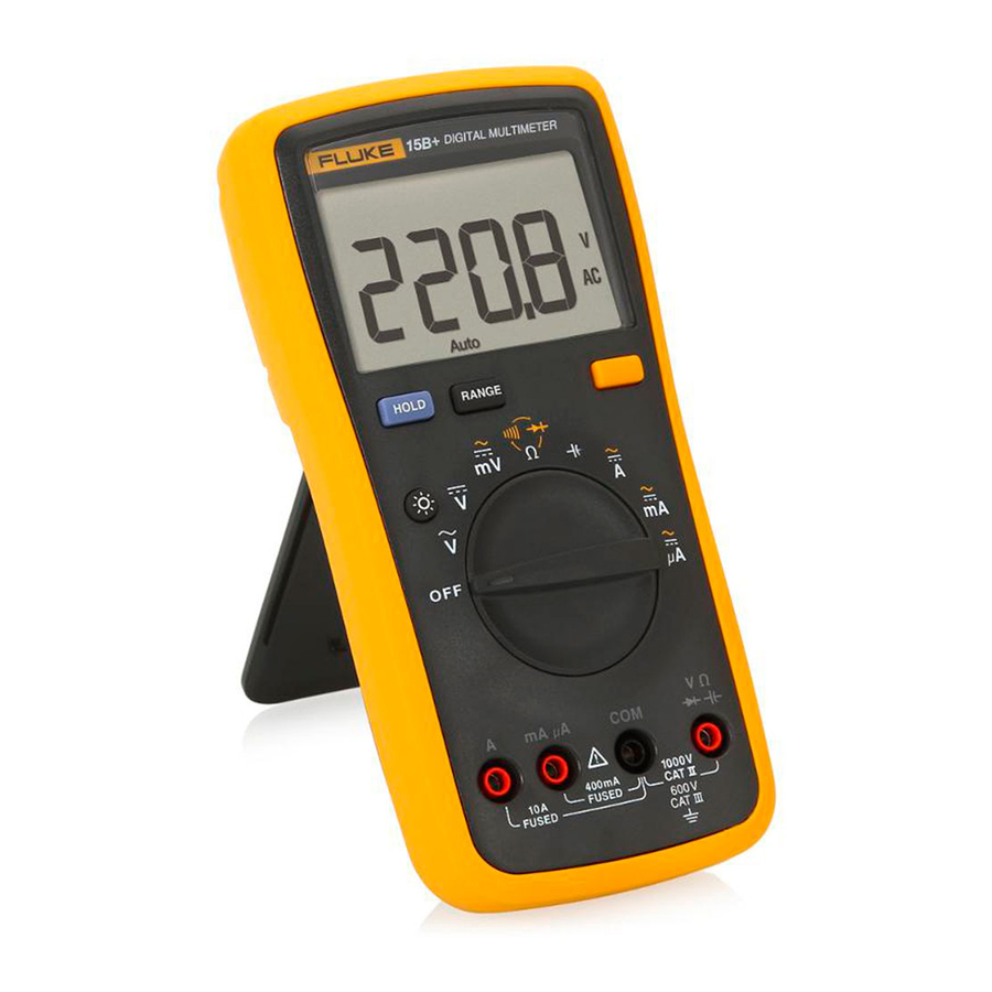
Page 1: Digital Multimeter
15B+/17B+/18B+ Digital Multimeter Calibration Manual April 2016 © 2016 Fluke Corporation. All rights reserved. Specifications are subject to change without notice. All product names are trademarks of their respective companies. -
Page 3: Table Of Contents
Table of Contents Title Page Introduction .................... 1 How to Contact Fluke ................1 Safety Information ................. 2 General Specifications ................5 Accuracy Specifications ................ 6 AC and DC Voltage ................6 AC and DC Current ................6 Diode Test, Temperature, Resistance, Capacitance, Frequency, and Duty Cycle .................. - Page 4 15B+/17B+/18B+ Calibration Manual...
-
Page 6: Introduction
Introduction The Fluke 15B+/17B+/18B+ Digital Multimeters (the Product or UUT) are 4000-count instruments. The Product is battery powered with a digital display. Except where noted, the descriptions and instructions in this manual apply to all models. Unless otherwise identified, all illustrations show the 17B+. -
Page 7: Safety Information
15B+/17B+/18B+ Calibration Manual Safety Information A Warning identifies conditions and procedures that are dangerous to the user. A Caution identifies conditions and procedures that could cause damage to the Product or the equipment under test. Table 1 is a list of the international electrical symbols used on the Product and in this manual. - Page 8 Digital Multimeter Safety Information • Keep fingers behind the finger guards on the probes. • Remove all probes, test leads, and accessories before the battery door is opened. • Do not exceed the Measurement Category (CAT) rating of the lowest rated individual component of a Product, probe, or accessory.
- Page 9 15B+/17B+/18B+ Calibration Manual Table 1. Symbols Symbol Description Symbol Description AC (Alternating Current) Earth Ground DC (Direct Current) Fuse Diode Capacitance WARNING. HAZARDOUS Battery VOLTAGE. Risk of electrical shock. WARNING. RISK OF DANGER. Consult user documentation.
-
Page 10: General Specifications
Digital Multimeter General Specifications General Specifications Maximum voltage between any Terminal and Earth Ground: 1000 V Display (LCD) ............4000 counts, updates 3/sec Battery Type ............2 AA, IEC LR6 Battery Life ............500 hours minimum (50 hours in LED Test mode without load. The hours with load depends on the type of LED under test.) Temperature Operating ............ -
Page 11: Accuracy Specifications
15B+/17B+/18B+ Calibration Manual Accuracy Specifications Accuracy is specified for 1 year after calibration, at operating temperatures of 18 °C to 28 °C, relative humidity at 0 % to 75 %. Accuracy specifications take the form of: ±([% of Reading] + [Number of Least Significant Digits]). AC and DC Voltage Accuracy Function... -
Page 12: Diode Test, Temperature, Resistance, Capacitance, Frequency, And Duty Cycle
Digital Multimeter Accuracy Specifications Diode Test, Temperature, Resistance, Capacitance, Frequency, and Duty Cycle Accuracy Function Range Resolution 15B+ 17B+ 18B+ Diode Test 2.000 V 0.001 V 10 % 50.0 °C – 2 % +1 °C 400.0 °C Temperature 0.1 °C 2 °C 0 °C –... -
Page 13: Led Test And Continuity Threshold
15B+/17B+/18B+ Calibration Manual LED Test and Continuity Threshold Function Illumination Range Measurement Range Resolution Accuracy LED V Test (LED Test 1.00 V to 6.00 V Socket) LED V Test (Test Leads) 1.00 V to 6.00 V 1.00 V to 6.00 V 0.01 V 10 % 70 Ω... - Page 14 Digital Multimeter Accuracy Specifications h Static Awareness h Semiconductors and integrated circuits can be damaged by electrostatic discharge during handling. This notice explains how to minimize damage to these components. 1. Understand the problem. 2. Learn the guidelines for proper handling. 3.
-
Page 15: Disassembly
See the Calibration sections for calibration adjustment. If the UUT still fails to meet the range indicated, see How to Contact Fluke. Table 2 lists the equipment required for the performance tests. Table 2. Required Equipment for Performance Test 15B+ and 17B+... -
Page 16: Performance Tests For The 15B+ And 17B
Digital Multimeter Performance Tests Performance Tests for the 15B+ and 17B+ Before doing the performance test, make sure to warm up the calibrator. To test each function and operating ranges: 1. For each step in Table 3, set the UUT to the specified function and range. 2. - Page 17 15B+/17B+/18B+ Calibration Manual Table 0-3. Performance Specifications for 15B+ and 17B+ (cont.) Calibrator output UUT reading limit Step Function 15B+ 17B+ Frequency Lower Upper Value or Amplitude Limit Limit 0 Ω Ω √ √ -0.3 350 Ω Ω √ √ 348.0 352.0 Ω...
-
Page 18: Performance Test For 18B
Digital Multimeter Performance Tests Performance Test for 18B+ Before doing the performance test, make sure to warm up the calibrator. To test each function and operating ranges: 1. For each step in Table 4, set the UUT to the specified function and range. 2. - Page 19 15B+/17B+/18B+ Calibration Manual Table 4. Performance Specifications for 18B+ (cont.) Calibrator Output UUT reading limit Step Function Frequency or Lower Limit Upper Limit Value Amplitude 0 Ω Ω -0.3 350 Ω Ω 348.0 352.0 Ω 3.5 kΩ 3.480 3.520 Ω 35 kΩ...
-
Page 20: Calibration Procedures
Table 5. Required Equipment for Calibration Equipment Required Characteristics Recommended Model Calibrator FLUKE 5522A Potentiometer (17B+) Manually adjustable To enter calibration mode: 1. Remove the battery door and battery. See Figure 1. 2. Remove the calibration sticker. See Figure 3. -
Page 21: Calibration For 15B+ And 17B
15B+/17B+/18B+ Calibration Manual • Connect the UUT signal input terminal to the calibrator (5522A or other calibrator.) icr07.eps Figure 4. Calibration Connections 4. To put the UUT in calibration mode, use a small probe to push the calibration button (CAL1) See Figure 5 for 15B+ and 17B+ and Figure 7 for 18B+. Calibration for 15B+ and 17B+ For each function in Table 7: 1. - Page 22 Digital Multimeter Calibration Procedures CAL1 CAL1 HOLD1 icr03.eps Figure 5. Calibration Adjustment for 15B+ and 17B+ 5. Enter the calibration values on the calibrator. 6. For each function, push to confirm. The display shows the function and the high voltage mark. See Table 6. Table 6.
-
Page 23: Calibration For 18B
15B+/17B+/18B+ Calibration Manual icr05.eps Figure 6. Temperature Adjustment for 17B+ Calibration for 18B+ For each function in Table 8: 1. Turn the rotary selection knob to the function to be calibrated. 2. On the PCB, short CAL1 and WP6 together. See Figure 7. CAL1 CAL1 icr04.eps...
Need help?
Do you have a question about the 15B+ and is the answer not in the manual?
Questions and answers