Fluke 15B+, 17B+, 18B+ Manual
- User manual (20 pages) ,
- Calibration manual (20 pages)
Advertisement
Introduction
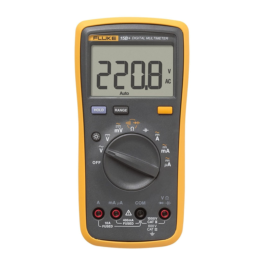
The Fluke 15B+/17B+/18B+ Digital Multimeters (the Product or UUT) are 4000-count instruments. The Product is battery powered with a digital display.
Except where noted, the descriptions and instructions in this manual apply to all models.
Unless otherwise identified, all illustrations show the 17B+.
General Specifications
| Maximum voltage between any Terminal and Earth Ground: | 1000 V |
| Display (LCD) | 4000 counts, updates 3/sec |
| Battery Type | 2 AA, IEC LR6 |
| Battery Life | 500 hours minimum (50 hours in LED Test mode without load. The hours with load depends on the type of LED under test.) |
| Temperature | |
| Operating | 0°C to 40°C |
| Storage | -30°C to 60°C |
| Relative Humidity | |
| Operating Humidity | Non-condensing (<10°C); ≤90% RH from 10°C to 30°C; ≤75% RH at 30°C to 40°C |
| Operating Humidity, 40 MΩ Range | ≤80% RH at 10°C to 30°C; ≤70% RH at 30°C to 40°C |
| Altitude | |
| Operating | 2000 m |
| Storage | 12 000 m |
| Temperature Coefficient | 0.1 X (specified accuracy) / °C (<18°C or >28°C) |
| Fuse protection for current inputs | 440 mA, 1000 V, IR 10 kA min 11 A, 1000 V, IR 20 kA min |
| Size (HxWxL) | 183 mm x 91 mm x 49.5 mm |
| Weight | 455 g |
| Ingress Protection | IEC 60529: IP40 non-operating |
| Safety | IEC 61010-1: Pollution degree 2 IEC 61010-2-033: CAT III 600 V, CAT II 1000 V |
Electromagnetic Compatibility
| International | IEC 61326-1: Basic Electromagnetic Environment: IEC 61326-2-2 CISPR 11: Group 1, Class A Group 1: Equipment has intentionally generated and/or use conductively coupled radio-frequency energy which is necessary for the internal functioning of the equipment itself. Class A: Equipment is suitable for use in all establishments other than domestic and those directly connected to a low voltage power supply network which supplies buildings used for domestic purposes. There may be potential difficulties in ensuring electromagnetic compatibility in other environments, due to conducted and radiated disturbances. |
| Korea (KCC) | Class A Equipment (Industrial Broadcasting & Communication Equipment) Class A: Equipment meets requirements for industrial electromagnetic wave equipment and the seller or user should take notice of it. This equipment is intended for use in business environments and not to be used in homes. |
| USA (FCC) | 47 CFR 15 subpart B. This product is considered an exempt device per clause 15.103. |
Accuracy Specifications
Accuracy is specified for 1 year after calibration, at operating temperatures of 18°C to 28°C, relative humidity at 0% to 75%. Accuracy specifications take the form of: ±([% of Reading] + [Number of Least Significant Digits]).
AC and DC Voltage
| Function | Range | Resolution | Accuracy | ||
| 15B+ | 17B+ | 18B+ | |||
AC Volts (40 Hz – 500 Hz)[1]  | 4.000 V 40.00 V 400.0 V 1000 V | 0.001 V 0.01 V 0.1 V 1 V | 1.0% + 3 | 1.0% + 3 | 1.0% + 3 |
AC Millivolts | 400.0 mV | 0.1 mV | 3.0% + 3 | 3.0% + 3 | 3.0% + 3 |
DC Millivolts | 400.0 mV | 0.1 mV | 1.0% + 10 | 1.0% + 10 | 1.0% + 10 |
DC Volts | 4.000 V 40.00 V 400.0 V 1000 V | 0.001 V 0.01 V 0.1 V 1 V | 0.5% + 3 | 0.5% + 3 | 0.5% + 3 |
[1] All ac, Hz, and duty cycle are specified from 1% to 100% of range. Inputs below 1% of range are not specified.
AC and DC Current

Diode Test, Temperature, Resistance, Capacitance, Frequency, and Duty Cycle

LED Test and Continuity Threshold
| Function | Illumination Range | Measurement Range | Resolution | Accuracy |
| LED VF Test [1] F (LED Test Socket) | 1.00 V to 6.00 V | NA | NA | NA |
| LED VF Test [2] F (Test Leads) | 1.00 V to 6.00 V | 1.00 V to 6.00 V | 0.01 V | 10% [3] |
| Continuity Threshold | NA | NA | NA | 70 Ω |
[1] Open circuit test voltage is ±12 V and short-circuit current is <±5 mA (typical).
[2] Open circuit test voltage is ±12 V and short-circuit current is <±3 mA (typical).
[3] VF measurement with driving current under 2.2 mA ±0.4 mA.
Input Characteristics
| Function | Overload Protection | Input Impedance (Nominal) | Common Mode Rejection Ratio >60 dB at dc, | Normal Mode Rejection Ratio |
| AC Volts | 1000 V [1] | >10 MΩ, <100 pF | >60 dB at dc, 50 Hz or 60 Hz | _ |
| AC Millivolts | 400 mV | >1 MΩ, <100 pF | >80 dB at dc, 50 Hz or 60 Hz | _ |
| DC Volts | 1000 V [1] | >10 MΩ, <100 pF | >100 dB at dc, 50 Hz or 60 Hz | >60 dB at 50 Hz or 60 Hz |
| DC Millivolts | 400 mV | >1 MΩ, <100 pF | >80 dB at dc, 50 Hz or 60 Hz | _ |
[1] 106 V Hz Max
 Static Awareness
Semiconductors and integrated circuits can be damaged by electrostatic X discharge during handling. This notice explains how to minimize damage to these components.
- Understand the problem.
- Learn the guidelines for proper handling.
- Use the proper procedures, packaging, and bench techniques.
Follow these practices to minimize damage to static sensitive parts.

To prevent electric shock or personal injury. Deenergize the product and all active circuits before opening a product enclosure, touching or handling any PCBs or components.

- Minimize handling.
- Handle static-sensitive parts by non-conductive edges.
- Do not slide staticsensitive components over any surface.
- When removing plug-in assemblies, handle only by non-conductive edges.
- Never touch open-edge connectors except at a static-free work station.

- Keep parts in the original containers until ready for use.
- Use static shielding containers for handling and transport.
- Avoid plastic, vinyl, and Styrofoam ® in the work area.

- Handle static-sensitive parts only at a staticfree work station.
- Put shorting strips on the edge of the connector to help protect installed static-sensitive parts.
- Use anti-static type solder extraction tools only.
- Use grounded-tip soldering irons only.
Disassembly
To prevent false readings, which could lead to possible electric shock or personal injury, replace the batteries as soon as the low battery indicator (![]() ) appears. To prevent damage or injury:
) appears. To prevent damage or injury:
- Install ONLY replacement fuses with the specified amperage, voltage, and interrupt ratings.
- Disconnect test leads before opening the case or the battery door.
To remove the battery door and battery for adjustments and calibration, see Figure 1.

Figure 1. Remove the battery
Performance Tests
Use the performance tests to make sure the UUT is operating properly and to make sure the UUT is accurate. If the UUT fails any part of the performance test, repair and/or calibration adjustment are required. See the Calibration sections for calibration adjustment. If the UUT still fails to meet the range indicated, see How to Contact Fluke. Table 2 lists the equipment required for the performance tests.
Table 2. Required Equipment for Performance Test 15B+ and 17B+
| Equipment | Recommended Model |
| Calibrator | FLUKE 5522A |
Performance Tests for the 15B+ and 17B+
Before doing the performance test, make sure to warm up the calibrator. To test each function and operating ranges:
- For each step in Table 3, set the UUT to the specified function and range.
- Connect the source to the input jacks on the UUT.
- Apply the output from the source.
- Make sure the readings on the UUT display are within the limits in Table 3.
Table 3. Performance Specifications for 15B+ and 17B+


Performance Test for 18B+
Before doing the performance test, make sure to warm up the calibrator. To test each function and operating ranges:
- For each step in Table 4, set the UUT to the specified function and range.
- Connect the source to the input jacks on the UUT.
- Apply the output from the source.
- Make sure the readings on the UUT display are within the limits in Table 4.
- For the LED test, put the LEDs as shown in Figure 2. The test passes if the LED lights.

Figure 2. LED Test

Table 4. Performance Specifications for 18B+


Calibration Procedures
Table 5 list equipment that is required to calibrate the Product.
Table 5. Required Equipment for Calibration
| Equipment | Required Characteristics | Recommended Model |
| Calibrator | FLUKE 5522A | |
| Potentiometer (17B+) | Manually adjustable |
To enter calibration mode:
- Remove the battery door and battery. See Figure 1.
- Remove the calibration sticker. See Figure 3.

Figure 3. Remove Calibration Sticker

- See Figure 4 to make the connections to power and a calibrator:
- Use a contact spring to connect to a 3 V dc power supply.
- Connect the UUT signal input terminal to the calibrator (5522A or other calibrator.)

Figure 4. Calibration Connections

- To put the UUT in calibration mode, use a small probe to push the calibration button (CAL1) See Figure 5 for 15B+ and 17B+ and Figure 7 for 18B+.
Calibration for 15B+ and 17B+
For each function in Table 7:
- Turn the rotary selection knob to the function to be calibrated.
- Set calibrator output for the appropriate signal.
- Wait 4 seconds for the reading to stabilize then push
![]() to confirm and forward next step.
to confirm and forward next step. - On the PCB, short CAL1 and WP6 together. See Figure 5.

Figure 5. Calibration Adjustment for 15B+ and 17B+
 to confirm and forward next step.
- Enter the calibration values on the calibrator.
- For each function, push
![]() to confirm. The display shows the function and the high voltage mark. See Table 6.
to confirm. The display shows the function and the high voltage mark. See Table 6.
 to confirm. The display shows the function and the high voltage mark. See Table 6.
Table 6. LCD Indications

- For the 17B+ temperature calibration:
- Use an adjustable potentiometer to make a manual adjustment. See Figure 6.

Figure 6. Temperature Adjustment for 17B+
- Adjust to 0.1°C to 0.3°C at 0°C input.
- Use an adjustable potentiometer to make a manual adjustment. See Figure 6.
- When calibration is complete, turn off the UUT.

Table 7. All Functions Adjustments 15B+ and 17B+

Calibration for 18B+
For each function in Table 8:
- Turn the rotary selection knob to the function to be calibrated.
- On the PCB, short CAL1 and WP6 together. See Figure 7.

Figure 7. Calibration Adjustment 18B+

- Connect the UUT signal input terminal to the calibrator (F5522A or other calibrator.)
- Enter the calibration values on the calibrator.
- For each function, push
![]() to confirm.
to confirm. - When calibration is complete, turn off the UUT.
 to confirm.
Table 8. All Functions Adjustment 18B+

How to Contact Fluke
To contact Fluke, call one of the following telephone numbers:
1.800.561.8187
information@itm.com
Safety Information
A Warning identifies conditions and procedures that are dangerous to the user.

A Caution identifies conditions and procedures that could cause damage to the Product or the equipment under test.
Table 1 is a list of the international electrical symbols used on the Product and in this manual. Review the safety information and comply with the safe working practices.
To prevent possible electrical shock, fire, or personal injury:
- Carefully read all instructions.
- Read all safety information before you use the Product.
- Use the Product only as specified, or the protection supplied by the Product can be compromised.
- Do not use the Product around explosive gas, vapor, or in damp or wet environments.
- Examine the case before you use the Product. Look for cracks or missing plastic. Carefully look at the insulation around the terminals.
- Do not use the Product if it is damaged.
- Do not use the Product if it operates incorrectly.
- Comply with local and national safety codes. Use personal protective equipment (approved rubber gloves, face protection, and flame-resistant clothes) to prevent shock and arc blast injury where hazardous live conductors are exposed.
- Use only correct measurement category (CAT), voltage, and amperage rated probes, test leads, and adapters for the measurement.
- Do not use test probes in CAT III environments without the protective cap installed. The protective cap decreases the exposed probe metal to <4 mm. This decreases the possibility of arc flash from short circuits.
- Measure a known voltage first to make sure that the Product operates correctly.
- Limit operation to the specified measurement category, voltage, or amperage ratings.
- Do not apply more than the rated voltage, between the terminals or between each terminal and earth ground.
- Do not touch voltages > 30 V ac rms, 42 V ac peak, or 60 V dc.
- Do not use test leads if they are damaged. Examine the test leads for damaged insulation and measure a known voltage.
- Keep fingers behind the finger guards on the probes.
- Remove all probes, test leads, and accessories before the battery door is opened.
- Do not exceed the Measurement Category (CAT) rating of the lowest rated individual component of a Product, probe, or accessory.
- Remove the batteries if the Product is not used for an extended period of time, or if stored in temperatures above 50°C. If the batteries are not removed, battery leakage can damage the Product.
- Replace the batteries when the low battery indicator (
![]() ) shows to prevent incorrect measurements.
) shows to prevent incorrect measurements. - Use the correct terminals, function, and range for measurements.
- Disconnect all test leads from any hazardous voltage before switching to the LED TEST function. Refer to the LED TEST section for proper measurement technique and interpretation of results (for 18B+ only).
- The battery door must be closed and locked during verification.
- Do not operate the Product with covers removed or the case open. Hazardous voltage exposure is possible.
- Do not apply hazardous voltages during the calibration procedure.
 ) shows to prevent incorrect measurements.
Table 1. Symbols

Documents / Resources
References
Download manual
Here you can download full pdf version of manual, it may contain additional safety instructions, warranty information, FCC rules, etc.
Advertisement


Need help?
Do you have a question about the 15B+ and is the answer not in the manual?
Questions and answers