Table of Contents
Advertisement
Advertisement
Table of Contents

Related Manuals for Advantech ADAM 4100


Summary of Contents for Advantech ADAM 4100
- Page 1 ADAM 4100 Industrial Grade Data Acquisition Modules User's Manual...
- Page 2 Advantech Co., Ltd. Information provided in this manual is intended to be accurate and reliable. However, Advantech Co., Ltd. assumes no responsibility for its use, nor for any infringements upon the rights of third parties, which may result from its use.
-
Page 3: Table Of Contents
Table of Contents Chapter 1 Introduction ..…..……....…....………….. 1-1 Chapter 2 Installation Guideline ....…....…....2-1 2.1 System Requirements to set up an ADAM network ..…....2-2 2.2 Basic configuration and hook-up ....……......2-5 2.3 Baud rate and Checksum .........……......2-7 2.4 Multiple Module Hookup .......………......2-9 2.5 Programming Example........…….......2-10 Chapter 3 I/O Modules ..........…...... - Page 4 Appendix A Utility Software......…..…………...…..A-1 A.1 Utility overview....…...............A-2 A.2 Firmware update............……..A-6 A.3 Address mode..................A-8 A.4 Locate mode........…..........A-9 Appendix B ADAM-4100 I/O Modbus Mapping Table..…....B-1 B.1 ADAM-4117 8-channel Analog Input Module....…..... B-3 B.2 ADAM-4118 8-channel Thermocouple Input Module....B-4 B.3 ADAM-4150 Digital Input/Output Module.......…..B-5 B.4 ADAM-4168 8 Relay Output Module………………..…....B-9 Appendix C Technical Diagrams .........…......C-1 C.1 ADAM Dimensions ..........…......C-2...
-
Page 5: Chapter 1 Introduction
Introduction... - Page 6 Support +/- 15V Input Range (ADAM-4117) Support Filter Auto-tuning or Filter-out 50Hz/60Hz (ADAM-4117/4118) Digital Filter Function (ADAM-4150) DI channels allow to be used as 3 KHz counter (ADAM-4150) DO channels support pulse output function (ADAM-4150 / 4168) 1-2 ADAM 4100 Series User’s Manual...
- Page 7 Chapter ADAM-4100 Module with LED Display ADAM-4100 series own a series of LED display on the face. They let you monitor the status and also allow reading the address of ADAM- 4100. Actually, they have original two operating mode (Initial mode and Normal mode).
- Page 8 ADAM modules mount on any panel, on provided brackets, on DIN rails or may be stacked together. The RS-485 network, together with screw-terminal plug connectors, allows for system expansion, reconfiguration and repair without disturbing field wiring. 1-4 ADAM 4100 Series User’s Manual...
-
Page 9: Chapter 2 Installation Guideline
Installation Guideline... -
Page 10: System Requirements To Set Up An Adam Network
. Power ripples must be limited to 5 V peak to peak while the voltage in all cases must be maintained between +10 and +48 . All power supply specifications are referenced at module 2-2 ADAM 4100 Series User’s Manual... - Page 11 Chapter connector. When modules are powered remotely, the effects of DC voltage drops must be considered. All modules use on-board switching regulators to sustain good efficiency over the 10 to 48 V input range; therefore, we can assume that the actual drawn current is inversely proportional to the DC voltage. Figure 2-1 Power Supply Connections We advise the following standard colors (as indicated on the modules) for each power line:...
- Page 12 255 ADAM modules. As with the Converter module, the Repeater module is not addressable by the host and the baud rate must be reset by changing the switch inside the module. The factory default setting is 9600 baud. 2-4 ADAM 4100 Series User’s Manual...
-
Page 13: Basic Configuration And Hook-Up
Chapter 2.2 Basic configuration and hook-up Before placing a module in an existing network, the module should be configured. Though all modules are initially configured at the factory, it is recommended to check if the baud rate is set correctly beforehand. Default Factory Settings Baud rate: 9600 Bit/sec. - Page 14 The easiest way to configure the ADAM module is by using the ADAM utility software. It is a user friendly structured menu program that will guide you through every step of the configuration. (See Appendix A, Utility Software) 2-6 ADAM 4100 Series User’s Manual...
-
Page 15: Baud Rate And Checksum
Chapter Changing the protocol from ADAM ASCII to Modbus Some ADAM-4100 modules support both ADAM ASCII and Modbus protocols, and the factory default setting of these modules is ADAM ASCII protocol. If you would like to configure the modules to Modbus protocol, please refer to Appendix G which describes how to change the protocol in ADAM utility. - Page 16 • Wait at least 7 seconds to let self calibration and ranging take effect. • Check the settings (If the baud rate has changed, the settings on the host computer should be changed accordingly). 2-8 ADAM 4100 Series User’s Manual...
-
Page 17: Multiple Module Hookup
Chapter 2.4 Multiple Module Hookup The Figure below is an example of how ADAM modules are connected in a multiple module network: Figure 2-4 Multi-module Connection Chapter 2 installation Guideline 2-9... -
Page 18: Programming Example
Step 1. Using ADAM Utility to check the settings as the following below: “Address = 01H”, “Baud rate = 9600” and “Checksum = Disabled”. Step 2. Run VB 6.0 and add a control via “Project\Component”. 2-10 ADAM 4100 Series User’s Manual... - Page 19 Chapter Step 3. Select “Microsoft Comm Control” Step 4. Add the Comm Control on the form. Chapter 2 installation Guideline 2-11...
- Page 20 Installation Guideline Step 5. Add three Command Buttons on the form as shown below Step 6. Add one Label and one Text on the form as shown below. 2-12 ADAM 4100 Series User’s Manual...
- Page 21 Chapter Step 7. Click OPEN Button and type in the following codes. The source codes are listed at the end of this section. Step 8. Click SEND Button and type in the following codes. The source codes are listed at the end of this section. Chapter 2 installation Guideline 2-13...
- Page 22 Step 10. Run the Project → Click OPEN to open COM1 → Click SEND to send the Get Temperature Reading Command. Now, you will find the reading the same as the displayed format shown below. 2-14 ADAM 4100 Series User’s Manual...
- Page 23 Chapter Program Source Codes: OPEN Command Button: Private Sub Command1_Click() ' Buffer to hold input string Dim Instring As String ' Use COM1. MSComm1.CommPort = 1 ' 9600 baud, no parity, 8 data, and 1 stop bit. MSComm1.Settings = "9600,N,8,1" ' Tell the control to read entire buffer when Input ' is used.
-
Page 24: Chapter 3 I/O Modules
I/O Modules... -
Page 25: The Common Specification Of Adam-4100 I/O Series
Max. communication distance: 4000 feet (1.2 km) Communication error checking with checksum Asynchronous data format: Advantech protocol: 1 start bit, 8 data bits, 1 stop bit, no parity Modbus protocol: 1 start bit, 8 data bits, 1 or 2 stop bit, parity check (none, odd, even) -
Page 26: Adam-4117 8-Channel Analog Input Module
Chapter 3.2 ADAM-4117 8-channel Analog Input Module The ADAM-4117 is a 16-bit, 8-channel analog input module that provides programmable input ranges for all channels. This module is an extremely cost-effective solution for industrial measuring and monitoring applications. It is not only able to endure under the harsh environment, but also hold a more robust design. - Page 27 Zero Drift ±6µV/° C Span Drift ±25 ppm/° C CMR @ 50/60 Hz 92 dB min. Built-in Dual Watchdog Timer Built-in TVS/ESD Protection Power Consumption 1.2 W @ 24 VDC Jumper setting Figure 3-2 ADAM-4117 Jumper setting 3-4 ADAM 4100 Series User’s Manual...
- Page 28 Chapter *There is a resister built into ADAM-4117 for the current input mode Figure 3-3 ADAM-4117 wiring application Chapter 3 I/O Modules 3-5...
-
Page 29: Adam-4118 8-Channel Thermocouple Input Module
( C) In order to satisfy various temperature requirements in one module, each analog channel is allowed to configure each individual range for several applications. ADAM-4118 Figure 3-4 ADAM-4018 8-channel Thermocouple Input Module 3-6 ADAM 4100 Series User’s Manual... - Page 30 Chapter Specification Analog Input Effective Resolution: 16-bit Channel:8 differential ASCII command and Modbus protocol Input type & range: Thermocouple 0 ~ 760 0 ~ 1370 -100 ~ 400 0 ~ 1000 500 ~ 1750 500 ~ 1750 500 ~ 1800 Voltage mode ±15mV, ±50mV, ±100mV, ±500mV, ±1V, ±2.5V Current mode...
- Page 31 I/O Modules Figure 3-5 ADAM-4118 jumper setting *There is a resister built into ADAM-4118 for the current input mode Figure 3-6 ADAM-4118 wiring application 3-8 ADAM 4100 Series User’s Manual...
- Page 32 Chapter NOTE: 1. Because the CJC sensor of ADAM-4118 is located in the side of channel 0 to 4, the measurement will have the difference ± 1 between channel 0 ~ 4 and channel 5 ~ 7. 2. The ADAM-4118 Input Range Accuracy for Thermocouple is showed as below ADAM-4118 Input Range Accuracy for Thermocouple Input Range...
-
Page 33: Adam-4150 Digital I/O Module
Furthermore, these DI channels can be used as 3 KHz counter. Aside from its intelligent DI functions, the Digital Output channels also support 1 KHz pulse output function. ADAM-4150 Figure 3-7 ADAM-4150 Digital I/O Module 3-10 ADAM 4100 Series User’s Manual... - Page 34 Chapter Specification Channels: - 7 input channels - 8 output channels Digital Input: Dry contact: - Logic level 0: Close to GND. - Logic level 1: Open Wet contact: - Logic level 0: +3V max. - Logic level 1: +10V to +30V Isolation voltage: 3000V Support 3 KHz counter Support Digital Filter Function...
- Page 35 I/O Modules Application Wiring Internal External Figure 3-8 TTL Digital Input (ADAM-4150) Internal External Figure 3-9 Contact Closure Input (ADAM-4150) 3-12 ADAM 4100 Series User’s Manual...
- Page 36 Chapter Figure 3-10 Digital Output used with SSR (ADAM-4150) Chapter 3 I/O Modules 3-13...
-
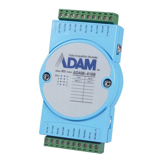
Page 37: Adam-4168 Relay Output Module
DC 30V at 2A. ADAM-4168 is excellent for ON/OFF control or low-power switching applications. Furthermore, all of the Digital Output channels can also support 100 Hz pulse output function. ADAM-4168 Figure 3-11 ADAM-4168 8-channel Relay Output Module 3-14 ADAM 4100 Series User’s Manual... - Page 38 Chapter Specification Number of Output Channel: 8 Form A Contact Rating: AC:125V@0.6A; 250V@0.3A DC:30V@2A; 110V@0.6A Breakdown Voltage : 750 V (50/60 Hz) Insulation Resistance: 1000MΩ minimum @500V Power Consumption: 0.4W(typical) 1.8W(Max) Relay response Time(typical): ON :3 ms Off: 1 ms Total switching time: 10 ms Support 100 Hz pulse output Support communication fail safety value...
-
Page 39: Chapter 4 Command Set
Command Set... -
Page 40: Introduction
Furthermore, an optional two-character checksum may be appended to the total string. Every command is terminated by a carriage return (cr). ALL COMMANDS SHOULD BE ISSUED IN UPPERCASE CHARACTERS! 4-2 ADAM 4100 Series User’s Manual... - Page 41 Chapter Before the command set is given, we provide an I/O module commands search table to help you find the commands that you wish to use. The command set is divided into the following three categories: • Analog Input Module commands •...
-
Page 42: Analog I/O Module Commands Search Table
4.4.13 $AAY Get communication WDT setting value 4.4.14 $AAMC Get Sample Rate of the Auto-Filter 4.4.15 #AAMKmm Set Software Filter Enable/Disable 4.4.16 $AAMD Read Software Filter channel Enable/Disable 4.4.17 #AAFQm Locate the module 4.4.18 4-4 ADAM 4100 Series User’s Manual... - Page 43 Chapter ADAM-4118 Command Table Command Syntax Command Description Section Set the address, input range, baud rate, data format, %AANNTTCCFF 4.4.1 checksum status and/or integration time #AAN Return the input value from channels number N 4.4.2 Return the input values from all channels of the 4.4.3 specified analog input module Calibrate the analog input module to correct for...
-
Page 44: Analog I/O Module Command Set
The layout of the 8-bit parameter is shown in figure 4-1. Bits 2 through 5 are not used and are set to 0. (cr) is the terminating character, carriage return (0Dh) Figure 4-1 Data format for 8-bit parameter 4-6 ADAM 4100 Series User’s Manual... - Page 45 Chapter (Continue %AANNTTCCFF) Response !AA(cr) if the command is valid. ?AA(cr) if an invalid parameter was entered or the INIT* terminal was not grounded when attempting to change baud rate or checksum settings. There is no response if the module detects a syntax or communication error, or even if the specified address does not exist.
- Page 46 Type K Thermocouple 0 to 1370 Type T Thermocouple -100 to 400 Type E Thermocouple 0 to 1000 Type R Thermocouple 500 to 1750 Type S Thermocouple 500 to 1750 Type B Thermocouple 500 to 1800 4-8 ADAM 4100 Series User’s Manual...
- Page 47 Chapter Table 4-2 Baud Rate Codes Baud Rate Code (hex) Baud Rate 1200 bps 2400 bps 4800 bps 9600 bps 19.2 kbps 38.4 kbps 57.6 kbps 115.2 kbps 230.4 kbps Chapter 4 Command Set 4-9...
- Page 48 #120(cr) response: >+1.4567(cr) The command requests the analog input module at address 12h to return the input value of channel 0. The analog input module responds an input value, +1.4567 volts, of channel 0. 4-10 ADAM 4100 Series User’s Manual...
- Page 49 Chapter 4.4.3 Name Analog Data In Description The command will return the input value from a specified (AA) module in the currently configured data format. Syntax #AA(cr) # is a delimiter character. AA (range 00-FF) represents the 2-character hexadecimal address of an analog input module. (cr) is the terminating character, carriage return (0Dh).
- Page 50 The module measures an input value of 820° C. Example command: #D1(cr) response: >+9999(cr) By returning a high value, +9999, the module at address D1h indicates that the measured input value exceeds the configured range. 4-12 ADAM 4100 Series User’s Manual...
- Page 51 Chapter 4.4.4 $AA0 Name Span Calibration Description Calibrates an analog input module to correct gain errors. Syntax $AA0(cr) $ is a delimiter character. AA (range 00-FF) represents the 2-character hexadecimal address of the analog input module 0 represents the span calibration command. (cr) is the terminating character, carriage return (0Dh).
- Page 52 NOTICE: An analog input module requires a maximum of 7 seconds to perform auto calibration and ranging after it has received an Offset Calibration command. During this interval, the module can not be addressed to perform any other actions. 4-14 ADAM 4100 Series User’s Manual...
- Page 53 Chapter 4.4.6 $AA2 Name Configuration Status Description The command requests the return of the configuration data from the analog input module at address AA. Syntax $AA2(cr) $ is a delimiter character. AA (range 00-FF) represents the 2-character hexadecimal address of the analog input module. 2 is the Configuration Status command.
- Page 54 The analog input module at address 45h responds with an input range of 2.5 volts, a baud rate of 9600 bps, an integration time of 50 ms (60 Hz). Engineering units are the currently configured data format, and no checksum function or checksum generation are in use. 4-16 ADAM 4100 Series User’s Manual...
- Page 55 Chapter 4.4.7 $AA5VV Name Enable/disable channels for multiplexing Description Enables/disables multiplexing simultaneously for separating channels of a specified input module Syntax $AA5VV(cr) $ is a delimiter character. AA (range 00-FF) represents the 2-character hexadecimal address of analog input module. 5 is the enable/disable channels command. VV are the two hexadecimal values which are interpreted as two binary words (4-bit) by the module.
- Page 56 The command asks the analog input module at address 02 to send the status of it input channels. The analog input module at address 02 responds with all its multiplex channels enabled (FF equals 1111 and 1111). 4-18 ADAM 4100 Series User’s Manual...
- Page 57 Chapter 4.4.9 $AAF Name Read Firmware Version Description The command requests the analog input module at address AA to return the version code of its firmware Syntax $AAF (cr) $ is a delimiter character. AA (range 00-FF) represents the 2-character hexadecimal address that you want to access.
- Page 58 AA (range 00-FF) represents the 2-character hexadecimal address of an analog input module. (Module Name) is the name of the module at address AA. (cr) is the terminating character, carriage return (ODh). 4-20 ADAM 4100 Series User’s Manual...
- Page 59 Chapter 4.4.11 $AA7CiRrr Name Single Channel Range Configuration Description This command configures the input type and range of the specified channel in an analog input module. Syntax $AA7CiRrr(cr) $ is a delimiter character. AA (range 00-FF) represents the 2-character hexadecimal address for configuration.
- Page 60 (cr) represents terminating character, carriage return (0Dh). Example command: $028C5(cr) response: !02C5R21(cr) The command reads the range of channel 5 in the analog input module at address 02. The response “R21” means Pt100 (IEC) 0~100° C. 4-22 ADAM 4100 Series User’s Manual...
- Page 61 Chapter 4.4.13 $AAXnnnn Name Watchdog Timer Setting Description This command set the Watchdog Timer communication cycle. Syntax $AAXnnnn(cr) $ is a delimiter character. AA (range 00-FF) represents the 2-character hexadecimal address which is to be read. X represents the setting of WDT command. nnnn (range 0000~9999) represents the specified value of communication cycle.
- Page 62 (range 0000~9999) represents the specified value of communication cycle. (cr) represents terminating character, carriage return (0Dh). Example command: $02Y(cr) response: !020030(cr) The command read the WDT cycle as 0030 from address 02 of the input module. 4-24 ADAM 4100 Series User’s Manual...
- Page 63 Chapter 4.4.15 #AAMC Name Get Sample Rate of the Auto-Filter Description This command read the Sample Rate of Auto-Filter. Syntax #AAMC(cr) # is a delimiter character. AA (range 00-FF) represents the 2-character hexadecimal address which is to be read. MC represents the reading Sample Rate of Auto-Filter command.
- Page 64 Hexadecimal 2 equals to binary 0010, which enables software filter of channel 5 and disables channels 4, 6, and Hexadecimal 3 equals to binary 0011, which enables software filter channel 0 and 1, disables channel 2, and 3. 4-26 ADAM 4100 Series User’s Manual...
- Page 65 Chapter 4.4.17 $AAMD Name Read Software Filter channel Enable/Disable Description This command reads the Filter status Software (Enable/disable) all Channels for Multiplexing Syntax #AAMD(cr) # is a delimiter character. AA (range 00-FF) represents the 2-character hexadecimal address which is to be read. MD represents the reading Filter status of Software...
- Page 66 (cr) represents terminating character, carriage return (0Dh). Example command: $01FQ1(cr) response: >01 (cr) The command at address 01 of the module lights up the “Status LED” for 10 seconds. 4-28 ADAM 4100 Series User’s Manual...
- Page 67 Chapter 4.4.19 $AA3 Name Returns the value of the CJC sensor Description Instructs the analog input module to read its CJC (Cold Junction Compensation) sensors and to return the acquired data. Syntax $AA3(cr) $ is a delimiter character. AA (range 00-FF) represents the 2-character hexadecimal address which contains the CJC Status you wish to retrieve.
- Page 68 NOTICE: An analog input module requires a maximum of 2 seconds to perform auto calibration and ranging after it received an CJC Calibration command. During this interval, the module can not be addressed to perform any other actions. 4-30 ADAM 4100 Series User’s Manual...
-
Page 69: Digital I/O Module Commands Search Table
Chapter 4.5 Digital I/O Module Commands Search Table ADAM-4150 Command Table Command Syntax Command Description Section Set the address, input range, baud %AANNTTCCFF rate, data format, checksum status 4.6.1 and/or integration time $AA2 Return the configuration parameters 4.6.2 Returns the values of the digital I/O $AA6 4.6.3 channels... - Page 70 Set DO pulse output counts 4.6.19 $aaERFFcc(cr) Read DO current pulse output counts 4.6.20 Clear Latch Alarm @AACACj(cr) 4.6.21 Start/Stop counter $AA5NS(cr) 4.6.22 Read Counter Start/Stop status $AA5N(cr) 4.6.23 Clear counter $AA6N(cr) 4.6.24 #AAFQm Locate the module 4.4.18 4-32 ADAM 4100 Series User’s Manual...
- Page 71 Chapter ADAM-4168 Command Table Command Syntax Command Description Section %AANNTTCCFF Set the address, input range, baud rate, data format, checksum status 4.6.1 and/or integration time $AA2 Return the configuration parameters 4.6.2 $AA6 Returns the values of the digital I/O 4.6.3 channels #AABB(data) Writes specified values to either a...
-
Page 72: Digital I/O Module Command Set
0. (Please see Figure 4-2) Bit 6 is the selection of checksum and bit 2 is the selection of protocol: (0: advantech, 1: modbus). (cr) is the terminating character, carriage return (0Dh). Figure 4-2 Checksum and protocol 4-34 ADAM 4100 Series User’s Manual... - Page 73 !24(cr) The command tries to configure module with address 23h to address 24h, baud rate of 9600 and no checksum checking. It also supports Advantech protocol. The response indicates that the configuration was successful. Table 4-3 Baudrate Codes Baud Rate Code (Hex)
- Page 74 Bits 3 through 5 and bit 0, 1, 7 are not used and are being set to 0. (See Figure 4-3) Bit 6 is the selection of checksum and bit 2 is the selection of protocol: (0: advantech, 1: modbus). (cr) is the terminating character, carriage return (ODh) 4-36 ADAM 4100 Series User’s Manual...
- Page 75 The command asks the digital I/O module at address 45h to send its configuration data. The digital I/O module at address 45h responds with baud rate of 9600, no checksum function. At last, the module supports Advantech protocol. Chapter 4 Command Set 4-37...
- Page 76 (dataOutput) two-character hexadecimal value which either is the feedback of a digital output channel or a relay. (dataInput) two-character hexadecimal value representing the input values of the digital I/O module. (cr) is the terminating character, carriage return (0Dh). 4-38 ADAM 4100 Series User’s Manual...
- Page 77 Chapter (continue $AA6) Example command: $336(cr) response: !112200(cr) This example is for ADAM-4150. The first two characters of the response, value 11h (00010001), indicate that digital output channels 0 and 4 are both ON, and channels 1, 2, 3, 5, 6, 7 are OFF. The following two characters of the response, 22h (00100010), indicate that digital input channels 1 and 5 are both HIGH, and channels 0, 2, 3, 4, 6, 7 are LOW.
- Page 78 The value 7A can be converted to the following 8 channels representations for ADAM-4150 and ADAM-4168: Digital Value: 0 1 1 1 1 0 1 0 ADAM-4150/4168 channel no. 7 6 5 4 3 2 1 0 4-40 ADAM 4100 Series User’s Manual...
- Page 79 Chapter (continue $AABB) Response >(cr) if the command was valid. ?AA(cr) if an invalid command has been issued. There is no response if the module detects a syntax or communication error, or even if the specified address does not exist. >...
- Page 80 > is a delimiter character indicating that a valid command was received. ? is a delimiter character indicating that the command was invalid. AA (range 00-FF) represents the responding 2-character hexadecimal address of the digital I/O module. 4-42 ADAM 4100 Series User’s Manual...
- Page 81 Chapter 4.6.6 $AAX1 Name Read Safety Value Description Read the time-out setting and pre-defined safety status of DO channels. Syntax $AAX1(cr) $ is a delimiter character. AA (range 00-FF) represents the 2-character hexadecimal address which is to be accessed. X1 is the read safety value command. Response ! TTTTDD(cr) if the command is valid.
- Page 82 ?AA(cr) if an invalid command has been issued. ! is a delimiter character indicating that a valid command was received ? is a delimiter character indicating that the command was invalid (cr) is the terminating character, carriage return (ODh). 4-44 ADAM 4100 Series User’s Manual...
- Page 83 Chapter 4.6.8 $AACIIIIIIIIIIIIIIOOOOOOOOOOOOOOOO Name Set the status of all DI/O channels Description Force the DI/O channels to different mode. Syntax $ AACIIIIIIIIIIIIIIOOOOOOOOOOOOOOOO $ is a delimiter character. AA (range 00-FF) represents the 2-character hexadecimal address which is to be accessed. C is the set/read the DI/O status command.
- Page 84 Enable Digital Filter DI Mode DI Mode DI Mode DO channel OO character mode L->H Delay Mode DO Mode DO Mode DO Mode DO Mode Pulse Output Mod L->H Delay Mode H->H Delay Mode 4-46 ADAM 4100 Series User’s Manual...
- Page 85 Chapter 4.6.9 $AAC Description Read the status of all DI/O channels Syntax $AAC(cr) $ is a delimiter character. AA (range 00-FF) represents the 2-character hexadecimal address which is to be accessed. C is the set/read the DI/O status command. (cr) is the terminating character, carriage return (0Dh) Response !AAIIIIIIIIIIIIIIOOOOOOOOOOOOOOOO(cr) command was valid.
- Page 86 > is a delimiter character indicating that a valid command was received. ? is a delimiter character indicating that the command was invalid. AA (range 00-FF) represents the responding 2-character hexadecimal address of the digital I/O module. 4-48 ADAM 4100 Series User’s Manual...
- Page 87 Chapter (continue $AACICjII) Example command: $02CIC202(cr) response: >(cr) The channel 2 is set from Low to High latch mode Chapter 4 Command Set 4-49...
- Page 88 ! is a delimiter character indicating that a valid command was received. II is defined as the same $AACICjII. ? is a delimiter character indicating that the command was invalid. AA (range 00-FF) represents the responding 2-character hexadecimal address of the digital I/O module. 4-50 ADAM 4100 Series User’s Manual...
- Page 89 Chapter 4.6.12 $AACOCjII Name Set DO status of specified channel Description Force the DO channel to different mode. Syntax $ AACOCjII(cr) $ is a delimiter character. AA (range 00-FF) represents the 2-character hexadecimal address which is to be accessed. CO is the set/read the DO status command. Cj is the channel j II is the two characters to set the DO mode OO=00...
- Page 90 ! is a delimiter character indicating that a valid command was received. OO is defined as the same $AACOCjOO. ? is a delimiter character indicating that the command was invalid. AA (range 00-FF) represents the responding 2-character hexadecimal address of the digital I/O module. 4-52 ADAM 4100 Series User’s Manual...
- Page 91 Chapter 4.6.14 $AA0CjLLLLLLLLHHHHHHHH Name Set DI filter input width Syntax $AA0CjLLLLLLLLHHHHHHHH(cr) $ is a delimiter character. AA (range 00-FF) represents the 2-character hexadecimal address which is to be accessed. 0 is the DI filter input command Cj is the channel j LLLLLLLL is the low level time and its range is 0x0~0xffffffff HHHHHHHH is the high level time and its range is...
- Page 92 HHHHHHHH is the high level time and its range is 0x0~0xffffffff Unit: 0.1ms ? is a delimiter character indicating that the command was invalid. AA (range 00-FF) represents the responding 2-character hexadecimal address of the digital I/O module. 4-54 ADAM 4100 Series User’s Manual...
- Page 93 Chapter 4.6.16 $ AA9n(lw)(hw)(ld)(hd) Name Set pulse output input width Syntax $AA9n(lw)(hw)(ld)(hd)(cr) $ is a delimiter character. AA (range 00-FF) represents the 2-character hexadecimal address which is to be accessed. 9 is the DI filter input command n is the channel n (lw): 8-hexadicimal chrs Low Width=>0x0~0xffffffff (hw): 8-hexadicimal chrs High Width=>0x0~0xffffffff (ld): 8-hexadicimal chrs Low Delay=>0x0~0xffffffff...
- Page 94 (ld): 8-hexadicimal chrs Low Delay=>0x0~0xffffffff (hd): 8-hexadicimal chrs High Delay=>0x0~0xffffffff Unit: 0.1ms ? is a delimiter character indicating that the command was invalid. AA (range 00-FF) represents the responding 2-character hexadecimal address of the digital I/O module. 4-56 ADAM 4100 Series User’s Manual...
- Page 95 Chapter 4.6.18 #AAN Name: Read Counter or Frequency Value Description: Instructs the counter/frequency module at address AA to read the counter or frequency value from counter 0 or 1 and to return the acquired data. Syntax: #AAN(cr) # is a delimiter character. AA (range 00-FF) represents the 2-character hexadecimal address which is to be accessed.
- Page 96 ! is a delimiter character indicating that a valid command was received. ? is a delimiter character indicating that the command was invalid. AA (range 00-FF) represents the responding 2-character hexadecimal address of the digital I/O module. 4-58 ADAM 4100 Series User’s Manual...
- Page 97 Chapter 4.6.20 $AAERFFcc Name Read DO current pulse output counts Syntax $AAERFFcc (cr) $ is a delimiter character. AA (range 00-FF) represents the 2-character hexadecimal address which is to be accessed. ERFF is the DO current pulse output counts command cc is the channel number ( 00~07 means Ch0~Ch7) (cr) is the terminating character, carriage return (0Dh).
- Page 98 (cr) represents terminating character, carriage return (0Dh) Example command: @05CAC1(cr) response: !05(cr) The counter module at address 05h and channel 1 are instructed to set both alarm states (High and Low) to OFF. The module confirms the execution. 4-60 ADAM 4100 Series User’s Manual...
- Page 99 Chapter 4.6.22 $AA5NS Name Start/Stop Counter Description Request the counter/frequency module to start or stop the counting for counter 0 or 1. Syntax $AA5NS(cr) $ is a delimiter character. AA (range 00-FF) represents the 2-character hexadecimal address which is to be accessed. 5 identifies the Start/Stop Counter command N determines whether the counter should be enabled or disabled.
- Page 100 (cr) is the terminating character, carriage return (0Dh). Example command: $0650(cr) response: !061(cr) The command requests the counter/frequency module at address 06 to return the status of counter 0. The addressed module replies that counter 0 is counting 4-62 ADAM 4100 Series User’s Manual...
- Page 101 Chapter 4.6.24 $AA6N Name Clear Counter Description Clears counter 0 or counter 1 of the specified counter/frequency module. Syntax $AA6N(cr) $ is a delimiter character. AA (range 00-FF) represents the 2-character hexadecimal address which is to be accessed. 6 the Clear Counter command. N determines which the counter should be cleared.
-
Page 102: Chapter 5 Calibration
Calibration... -
Page 103: Analog Input Module Calibration
3. Use a precise voltage source to calibrate the module through Vin+ and Vin-. 4. Execute the Zero Calibration command. This is also done through the ADAM utility software. Apply the indicating signal to input channel then save the exact value. Figure 5-1 Zero Calibration 5-2 ADAM 4100 Series User’s Manual... - Page 104 Chapter Figure 5-1(a) Zero Calibratio 5. Execute the Span Calibration command. This can be done with the ADAM utility software. Apply the indicating signal to input channel then save the exact value. Figure 5-2 Span Calibration Figure 5-2(a) Span Calibration 6.
- Page 105 C between channel 0 ~ 4 and channel 5 ~ 7. The following table is ADAM-4118 Input Range Accuracy for Thermocouple. 2. It had better send back to Advantech Repair Service (RMA) to conduct calibration if user find or doubt the standard shift.
-
Page 106: Appendix A Utility Software
Utility Software... -
Page 107: Utility Overview
Please do check if the COM port and related settings are correct. Figure A-1 Search screen A-2 ADAM 4100 Series User’s Manual... - Page 108 The data format is 1 start bit, 8 data bits, 1 stop bit, no parity for Advantech protocol and 1 start bit, 8 data bits, 1 or 2 stop bit, parity check (none, odd, even) for Modbus protocol only.
- Page 109 Figure A-3 Terminal Function You can type in the ADAM ASCII command in the text box and click on the Send button for testing commands which are listed in Chapter 4 Command Set. Figure A-4 Terminal Function A-4 ADAM 4100 Series User’s Manual...
- Page 110 Appendix A Notice: User can refer our help file to see more details for explanation of Utility operation. Appendix A Utility Software A-5...
-
Page 111: Firmware Update
Initial state. Then, click on the button “F/W Update”. Figure A-5 Firmware update Function (a) 2. The two dialog windows hint to search again directly. It doesn’t need to change ADAM status like initial or normal mode Figure A-6 Firmware update Function(b) A-6 ADAM 4100 Series User’s Manual... - Page 112 Appendix A 3. You will get a new sub window with firmware download option. The model is renamed 41XX, and the user can select the fast baud rate for download. Below the baud rate selection, you can choose the pathway for the firmware and download the file into the hardware. Figure A-7 Firmware update Function(c) 4.
-
Page 113: Address Mode
It shows that the ID is 19(13h). In the past, we can only use the utility for checking node ID. Now we can make use of the Address mode to help user read the module address directly. A-8 ADAM 4100 Series User’s Manual... -
Page 114: Locate Mode
Appendix A Figure A-10 Switch for Initial & Normal mode A.4 Software Filter & Locate mode 1. Auto Filter: when Integration time is selected the auto-filter, it will auto scan major noise and filter it actively. 2. Software Filter: to ignore the sudden noise. Following illustration shows its concept. - Page 115 “Locate” function to assist you. When you select a specific device, the LED that represents “Status” will be flashing for 8 minutes. If the “Locate” button is clicked, the “Status” LED will stay on. Figure A-11 Located mode Function A-10 ADAM 4100 Series User’s Manual...
-
Page 116: Appendix B Adam-4100 I/O Modbus Mapping Table
ADAM-4100 I/O Modbus Mapping Table... - Page 117 ADAM-4100 I/O Modbus Mapping Table The model list of ADAM-4100 I/O series support Modbus protocol Model Description ADAM-4117 8-channel Analog Input Module ADAM-4118 8-channel Thermocouple Input Module ADAM-4150 Digital I/O Module ADAM-4168 Relay Output Module B-2 ADAM 4100 Series User’s Manual...
-
Page 118: Adam-4117 8-Channel Analog Input Module
Appendix B.1 ADAM-4117 8-channel Analog Input Module ADDR 4X Channel Item Attribute Memo 10001 Burn-out 10002 Burn-out 10003 Burn-out 10004 Burn-out 10005 Burn-out 10006 Burn-out 10007 Burn-out 10008 Burn-out 40001 Current Value 40002 Current Value 40003 Current Value 40004 Current Value 40005 Current Value 40006... -
Page 119: Adam-4118 8-Channel Thermocouple Input Module
Type Code 40207 Type Code 40208 Type Code 40211 0x41 0x18 Module Name 1 40212 Module Name 2 0x50 0x00 40213 Version 1 0xa2 0x00 40214 Version 2 0x00 0x00 40221 Channel Enable 0x00 0xff B-4 ADAM 4100 Series User’s Manual... -
Page 120: Adam-4150 Digital Input/Output Module
Appendix B.3 ADAM-4150 Digital Input/Output Module ADDR 0X Channel Item Attribute Memo 00001 DI Signal 00002 DI Signal 00003 DI Signal 00004 DI Signal 00005 DI Signal 00006 DI Signal 00007 DI Signal 00017 DO Signal 00018 DO Signal 00019 DO Signal 00020 DO Signal... - Page 121 Counter Mode: Clear 00054 Counter(1) Counter Mode: Clear 00055 Overflow Counter Mode: Latch 00056 Status(read)/Clear Status(Write) Counter Mode: 00057 START(1)/STOP(0) Counter Mode: Clear 00058 Counter(1) Counter Mode: Clear 00059 Overflow Counter Mode: Latch 00060 Status(read)/Clear Status(Write) B-6 ADAM 4100 Series User’s Manual...
- Page 122 Appendix Pulse output Mode: 00061 Continue(1)/Non- Continue(0) Pulse output Mode: 00062 Continue(1)/Non- Continue(0) Pulse output Mode: 00063 Continue(1)/Non- Continue(0) Pulse output Mode: 00064 Continue(1)/Non- Continue(0) Pulse output Mode: 00065 Continue(1)/Non- Continue(0) Pulse output Mode: 00066 Continue(1)/Non- Continue(0) Pulse output Mode: 00067 Continue(1)/Non- Continue(0)
- Page 123 Reference: II&0x07=00 DI Mode. II&0x07=01 Counter Mode. II&0x07=02 Low-->High Latch Mode. II&0x07=03 High-->Low Latch Mode. II&0x07=04 Frequency Mode. II&0x20=20 DI Enable Counter record Function. II&0x40=40 DI Enable Digital Filter Function. II&0x80=80 DI Invert Mode B-8 ADAM 4100 Series User’s Manual...
-
Page 124: Adam-4168 8 Relay Output Module
Appendix B.4 ADAM-4168 8 Relay Output Module ADDR 0X Channel Item Memo Attribute 00017 Relay Output Value 00018 Relay Output Value 00019 Relay Output Value 00020 Relay Output Value 00021 Relay Output Value 00022 Relay Output Value 00023 Relay Output Value 00024 Relay Output Value Pulse output Mode:... - Page 125 DO High Delay width 40211 Module Name 1 40212 Module Name 2 40213 Versoin 1 40214 Versoin 2 40215 Comm Safety Enable 40216 Comm Safety Flag 40301 Reserved 40302 Reserved 40303 DO data in word B-10 ADAM 4100 Series User’s Manual...
-
Page 126: Appendix C Technical Diagrams
Technical Diagrams... -
Page 127: Adam Dimensions
Technical Diagrams C.1 ADAM Dimensions Figure C-1 ADAM Modules Dimensions C-2 ADAM 4100 Series User’s Manual... -
Page 128: Installation
Appendix C C.2 Installation C.2.1 DIN-Rail Mounting Figure C-2 DIN-Rail Adapter Appendix C Technical Diagrams C-3... - Page 129 Technical Diagrams Figure C-3 DIN-Rail Mounting C-4 ADAM 4100 Series User’s Manual...
- Page 130 Appendix C C.2.2 Panel Mounting Figure C-4 Panel Mounting Bracket Dimensions Appendix C Technical Diagrams C-5...
- Page 131 Technical Diagrams Figure C-5 Panel Mounting C-6 ADAM 4100 Series User’s Manual...
- Page 132 Appendix C C.2.3 Piggyback Stack Figure C-6 Piggyback Stack Appendix C Technical Diagrams C-7...
-
Page 133: Appendix D Data Formats And I/O Ranges
Data Formats and I/O Ranges... -
Page 134: Analog Input Formats
±5 V range. When the engineering unit format is used, the ADAM Series analog input modules are configured so that they automatically provide an over-range capability. The response to the Analog Data In command in this case is: +5.6530 (cr) D-2 ADAM 4100 Series User’s Manual... - Page 135 Appendix D D.1.2 Percent of FSR This mode is used by setting bits 0 and 1 of the data format/checksum /integration time parameter to 01. The format used in Percent of FSR consists of a plus (+) or minus (-) sign followed by five decimal digits including a decimal point.
- Page 136 Thermocouple Temperature Range Temperature Range Type (Degrees) (Hex) 0° C to 760° C 0000h - 7FFFh -100° C to 400° C E000h - 7FFFh 500° C to 1750° C 2492h - 7FFFh D-4 ADAM 4100 Series User’s Manual...
- Page 137 RS-485 Network...
- Page 138 Commands normally contain the address of the module that the host wants to communicate with. The module will respond back to the host once a match is occurred between the module and the command. E-2 ADAM 4100 Series User’s Manual...
-
Page 139: Appendix E Rs-485 Network
Appendix E E.1 Basic Network Layout Multi-drop RS-485 implies that there are two main wires in a segment. The connected modules are connected by the so called drop cables, and all the connections are in parallel. As a result, connecting or disconnecting of a node doesn’t affect the network as a whole. - Page 140 Figure E-2 Star structure Random This is a combination of daisychain and hierarchical structure Figure E-3 Random structure E-4 ADAM 4100 Series User’s Manual...
-
Page 141: Line Termination
Appendix E E. 2 Line Termination Whenever the cable is long or the modules are different in the network, signal reflections are very likely to occur. As a result, the quality of the signals will be affected, and the signals will be distorted. In order to eliminate this problem, a resistor should be implemented at the beginning and the end of the cable. - Page 142 NOTICE: The recommended wiring method that causes a minimum amount of reflection is daisy chaining where all receivers tap from one transmission line and needs to be terminated only twice. E-6 ADAM 4100 Series User’s Manual...
-
Page 143: Data Flow Control
Appendix E E.3 RS-485 Data Flow Control The RS-485 standard uses a single pair wire to send and receive data. However, some controls to the direction of the data flow are required. RTS (Request to Sent) and CTS (Clear to Sent) are the most commonly used methods. -
Page 144: Appendix F How To Use The Checksum Feature
How to use the Checksum feature... -
Page 145: Checksum Enable/Disable
ASCII values for the following characters: #, 0, and 5. The response checksum (9Dh) is the sum of the ASCII values for the following characters: “>”, “+”, “3”, “.”, “5”, “6”, “7”, and “1”. F-2 ADAM 4100 Series User’s Manual... - Page 146 Appendix F Example 2 This example explains how to calculate the checksum value of a Read High alarm limit command string: Case 1. (If the Checksum feature is disabled) Command: $07RH(cr) Response: !07+2.0500(cr) when the command is valid. Case 2. (If the Checksum feature is enabled) Command: $07RH25(cr) Response:...
- Page 147 How to use the Checksum feature Table F-1 Printable ASCII Characters HEX ASCII ASCII HEX ASCII HEX ASCII "" & < > F-4 ADAM 4100 Series User’s Manual...
- Page 148 Changing Configuration to Modbus Protocol...
-
Page 149: Appendix G Changing Configuration To Modbus Protocol
11. Update the settings by pressing the “Update” button. 12. Power off the module. 13. Turn the switch back to NORMAL* position. 14. The module is now ready to be placed in the Modbus network. G-2 ADAM 4100 Series User’s Manual...
Need help?
Do you have a question about the ADAM 4100 and is the answer not in the manual?
Questions and answers