Table of Contents
Advertisement
Quick Links
Advertisement
Table of Contents

Related Manuals for Asus ESC8000 G3


Summary of Contents for Asus ESC8000 G3
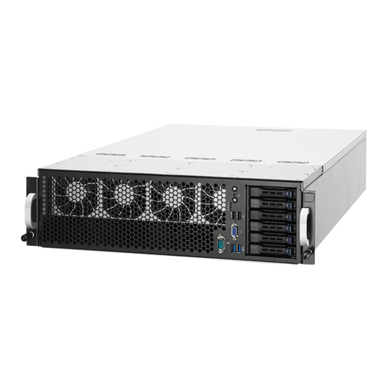
- Page 1 ESC8000 G3 3U Rackmount Server User Guide...
- Page 2 ASUSTeK COMPUTER INC. (“ASUS”). ASUS provides this manual “as is” without warranty of any kind, either express or implied, including but not limited to the implied warranties or conditions of merchantability or fitness for a particular purpose. In no...
-
Page 3: Table Of Contents
Contents Notices ........................viii Canadian Department of Communications Statement ........viii Australia statement notice ................viii Safety information ....................... x About this guide ......................xi Chapter 1: Product Introduction System package contents ................. 1-2 Serial number label ..................1-3 System specifications ................1-4 Front panel features ................... - Page 4 Onboard LEDs ..................4-18 Q-Code table ....................4-20 Chapter 5: BIOS setup Managing and updating your BIOS ............5-2 5.1.1 ASUS CrashFree BIOS 3 utility........... 5-2 5.1.2 ASUS EZ Flash Utility ..............5-3 5.1.3 BUPDATER utility ............... 5-4 BIOS setup program .................. 5-6 5.2.1...
- Page 5 Contents Advanced menu ..................5-10 5.4.1 ACPI Settings ................5-11 5.4.2 Smart Settings................5-11 5.4.3 NCT6779D Super IO Configuration .......... 5-12 5.4.4 Onboard LAN I210 Configuration ..........5-13 5.4.5 Serial Port Console Redirection ..........5-14 5.4.6 APM ..................5-17 5.4.7 Advanced Power Management Configuration ......
- Page 6 Contents Chapter 6: RAID Configuration Setting up RAID ..................6-2 6.1.1 RAID definitions ................6-2 6.1.2 Installing hard disk drives ............6-3 6.1.3 Setting the RAID item in BIOS ............ 6-3 6.1.4 RAID configuration utilities ............6-3 LSI Software RAID Configuration Utility ..........6-4 6.2.1 Creating a RAID set ..............
- Page 7 Running the Support DVD ..............7-13 ® Intel chipset device software installation ..........7-17 ® Installing the Intel I210 Gigabit Adapters driver ........7-19 VGA driver installation ................7-22 ® Intel Rapid Storage Technology enterprise 4.1 installation ....7-24 Appendix ASUS contact information ..................2...
-
Page 8: Notices
If you require assistance please call ASUS Customer Service 1300 2787 88 or visit us at https://www.asus.com/support/... - Page 9 ASUS REACH website at http://csr.asus.com/english/REACH.htm. ASUS Recycling/Takeback Services ASUS recycling and takeback programs come from our commitment to the highest standards for protecting our environment. We believe in providing solutions for you to be able to responsibly recycle our products, batteries, other components as well as the packaging materials.
-
Page 10: Safety Information
Safety information Electrical Safety • Before installing or removing signal cables, ensure that the power cables for the system unit and all attached devices are unplugged. • To prevent electrical shock hazard, disconnect the power cable from the electrical outlet before relocating the system. -
Page 11: About This Guide
About this guide Audience This user guide is intended for system integrators, and experienced users with at least basic knowledge of configuring a server. Contents This guide contains the following parts: Chapter 1: Product Introduction This chapter describes the general features of the server, including sections on front panel and rear panel specifications. - Page 12 Refer to the following sources for additional information, and for product and software updates. ASUS Server Web-based Management (ASWM) user guide This manual tells how to set up and use the proprietary ASUS server management utility. ASUS websites The ASUS websites worldwide provide updated information for all ASUS hardware and...
-
Page 13: Chapter 1: Product Introduction
Chapter 1: Product Introduction Product introduction This chapter describes the general features of the chassis kit. It includes sections on front panel and rear panel specifications. -
Page 14: System Package Contents
1.1 System package contents Check your system package for the following items. ESC8000 G3 Chassis ASUS 3U Rackmount Chassis Motherboard ASUS Z10PG-D24 Server Board 1 x MB Support DVD 1 x ASWM Enterprise DVD* 1 x ASMB8 SDVD 1 x Bag of Screws 3 x AC Power Cable 16 x GPU air ducts (8 for Intel Xeon PHi;... -
Page 15: Serial Number Label
1.2 Serial number label Before requesting support from the ASUS Technical Support team, you must take note of the product’s serial number containing 12 characters such as xxS0xxxxxxxx. See the figure below. With the correct serial number of the product, ASUS Technical Support team members can then offer a quicker and satisfying solution to your problems. -
Page 16: System Specifications
1.3 System specifications The ASUS ESC8000 G3 servers features the ASUS Z10PG-D24 Series server board that ® ® supports Intel LGA 2011-3 Xeon processor from the E5-2600 V3 product family. Model Name ESC8000 G3 2 x Socket R3 (LGA 2011-3) Processor / System Bus ® ®... - Page 17 Operating temperature: 10°C ~ 35°C Environment Non operating temperature: -40°C ~ 70°C Non operating humidity: 20% ~ 90% (Non-condensing) • Specifications are subject to change without notice. • Refer to www.asus.com for the latest OS AVL update. ASUS ESC8000 G3...
-
Page 18: Front Panel Features
Asset tag (hidden) Hot-swap 2.5-inch HDD Bays 1.5 Rear panel features The LAN ports and system power socket are located on the rear panel of the server. Power cord connector and Redundant power supply Full-length/Full-height expansion slots Half-length/Low-profile expansion slot The Dedicated Management LAN port is for the ASUS ASMB8-iKVM controller only. Chapter 1: Product Introduction... -
Page 19: Internal Features
A protection film is pre-attached to the front cover before shipping. Please remove the protection film before turning on the system for proper heat dissipation. WARNING HAZARDOUS MOVING PARTS KEEP FINGERS AND OTHER BODY PARTS AWAY ASUS ESC8000 G3... -
Page 20: Led Information
1.7 LED information 1.7.1 Front panel LEDs ESC8000 G3 Power button with LED RESET Location button with LED HDD Access LED Message LED LAN1 LED LAN2 LED RESET Display Icon Description status Power button with LED System power ON No activity HDD Access LED Blinking Read/write data into the HDD System is normal; no incoming event Message LED A hardware monitor event is indicated Normal status... -
Page 21: Lan (Rj-45) Leds
Linked ORANGE 100 Mbps connection BLINKING Data activity GREEN 1 Gbps connection Dedicated Management LAN (for ASMB8) ACT/LINK LED SPEED LED Status Description Status Description No link 10 Mbps connection ORANGE Linked ORANGE 100 Mbps connection BLINKING Data activity GREEN 1 Gbps connection ASUS ESC8000 G3... -
Page 22: Hdd Status Leds
1.7.3 HDD status LEDs ESC8000 G3 Power/Access LED Status LED RESET RESET HDD LED Description Green The installed HDD is in good condition HDD locate or HDD failure 1-10 Chapter 1: Product Introduction... -
Page 23: Chapter 2: Hardware Information
Chapter 2: Hardware Information Hardware Information This chapter lists the hardware setup procedures that you have to perform when installing or removing system components. -
Page 24: Chassis Covers
Chassis covers A protection film is pre-attached to the system cover before shipping. Remove the protection film before turning on the system for proper heat dissipation. To remove the rear chassis cover: Remove the two (A) thumbscrews on the rear then remove the four screws on the side (B). -
Page 25: Gpu Fan Air Duct
GPU fan air duct Use both of your hands in performing the steps. To remove the GPU fan airduct, remove the seven (7) screws on the GPU air duct then lift the airduct to remove it from the chassis. ASUS ESC8000 G3... - Page 26 To reinstall the GPU fan airduct. Align the rear corner edge of the GPU air duct inside the air tunnel on the mid board (A) then insert the front corner edge to the gap between the front system fans and the HDD casing (B).
-
Page 27: Central Processing Unit (Cpu)
Contact your retailer immediately if the PnP cap is missing, or if you see any damage to the PnP cap/socket contacts/motherboard components. ASUS shoulders the repair cost only if the damage is shipment/transit- related. - Page 28 Carefully lift the CPU air duct. Loosen the screws on the CPU heatsink. Chapter 2: Hardware Setup...
- Page 29 Lift and remove the CPU heatsink then set aside. Locate the CPU socket box in the motherboard. Align the system such that the socket box is facing toward you and the triangle mark is on your top-right position. Triangle mark ASUS ESC8000 G3...
- Page 30 Press down the load lever with your thumb (A), move it to the right until it is released from the retention tab (B), then gently lift the load lever (C). To prevent damage to the socket pins, do not remove the PnP cap unless you are installing a CPU.
- Page 31 Install the CPU into the slot. The CPU fits in only one correct orientation. DO NOT force the CPU into the socket to prevent bending the CPU pins on the socket. Triangle mark ASUS ESC8000 G3...
- Page 32 The PnP cap pops out of the load plate when the right load lever is inserted into the retention tab. Keep the PnP cap. ASUS will process Return Merchandise Authorization (RMA) requests only if the motherboard comes with the PnP cap on the LGA 2011-3 socket.
- Page 33 The Thermal Interface Material is toxic and inedible. DO NOT eat it. If it gets into your eyes or touches your skin, wash it off immediately and seek professional medical help. Repeat step 5 - 16 to install the other CPU. ASUS ESC8000 G3 2-11...
- Page 34 Align the CPU heatsink on top of the installed CPU ensuring that the screw holes on the CPU heatsink matches the screw holes on the socket box of the system. Tighten the four (4) screws on the CPU heatsink. 2-12 Chapter 2: Hardware Setup...
- Page 35 Replace the CPU air duct. Tighten the screws on the CPU air duct. ASUS ESC8000 G3 2-13...
-
Page 36: System Memory
System memory 2.4.1 Overview The motherboard comes with 24 Double Data Rate 4 (DDR4) Dual Inline Memory Modules (DIMM) sockets. The figure illustrates the location of the DDR4 DIMM sockets: 2-14 Chapter 2: Hardware Setup... -
Page 37: Memory Configurations
DIMMs. Doing so will prevent issues in installing the DIMMs next to the CPU. • Refer to ASUS Server AVL for the updated list of compatible DIMMs. • When installing only one DIMM in a single CPU configuration, install the DIMM on either A1 or B1. - Page 38 Dual CPU Configuration 2 CPU Configuration 2 DIMMs 4 DIMMs 8 DIMMs 12 DIMMs 16 DIMMs 20 DIMMs 24 DIMMs DIMM_A3 • • • • • • DIMM_A2 • • • • • • • DIMM_A1 DIMM_B3 • • DIMM_B2 •...
-
Page 39: Installing A Dimm On A Single Clip Dimm Socket
Press the retaining clip outward to unlock the DIMM. Remove the DIMM from the socket. Support the DIMM lightly with your fingers when pressing the retaining clips. The DIMM might get damaged when it flips out with extra force. ASUS ESC8000 G3 2-17... -
Page 40: Hard Disk Drives
Hard disk drives The ESC8000 G3 system supports hot-swap 2.5-inch SATA/SAS hard disk drives. The hard disk drive installed on the drive tray connects to the motherboard SATA/SAS ports via the SATA/SAS backplane. 2.5.1 Installing 2.5-inch SATA HDD/SAS HDD To install a 2.5-inch HDD: Press the spring lock to release the tray lever (A) and to partially eject the tray from the bay (B). - Page 41 Press the tray lever until it clicks in place. RESET Press the spring lock to secure the 2.5-inch SATA HDD/SAS HDD and drive tray assembly. RESET Repeat step 1-9 to install the other 2.5-inch SATA HDD/SAS HDDs. ASUS ESC8000 G3 2-19...
-
Page 42: Configuring An Expansion Card
2.5.2 Configuring an expansion card After installing the expansion card, configure it by adjusting the software settings. Turn on the system and change the necessary BIOS settings, if any. See Chapter 5 for information on BIOS setup. Assign an IRQ to the card. Refer to the Standard Interrupt assignments table for more information. -
Page 43: Cable Connections
Auxiliary Panel connector (from motherboard to front I/O board) Panel connector (from motherboard to front I/O board) System fan connectors (4-pin CPU_FAN1-4, FRNT_FAN1–8, HDD_FAN1-2 from motherboard to system fans) VGA_HDR1 connector (from motherboard to front I/O board) Serial port (COM port) ASUS ESC8000 G3 2-21... -
Page 44: Sata/Sas Backplane Cabling
SATA/SAS backplane cabling Front view Rear view HDD connectors 8-1 pin SMBUS1 connector ISAS2 connector 4-pin PWR1 connector ISAS1 connector 2-22 Chapter 2: Hardware Setup... -
Page 45: Installing M.2 Card
NGFF2 supports 2242 (22 x 42) M.2 cards. screw M.2 connector NGFF2 NGFF3 NGFF4 (default) stand screw Align and insert the M.2 card into the M.2 connector (NGFF1). Secure the M.2 card with the screw you removed in step 2. ASUS ESC8000 G3 2-23... -
Page 46: Installing Accelerators
Installing Accelerators • Use both of your hands in performing the following steps. • Read the documentation that comes with your GPU accelerator before installing them. • When installing more that one GPU accelerator, it is recommended to install the accelerator on PCIE9 slot first. - Page 47 For Nvidia 300W or above GPU cards, it is required to use the dedicated VGA power cables with black/white connector. The Nvidia 300W GPU card will not work, or may even cause damage to the system, if the wrong VGA power cable is used. ASUS ESC8000 G3 2-25...
- Page 48 Pass the VGA power cable inside the air duct as shown. • * Use the VGA power cable with red/white connector for general GPU/accelerators. • ** Use the VGA power cable with black/white connector for Nvidia 300W or above GPU card.
- Page 49 Insert the 6-pin power connector (white) of the VGA power cable to the insertion point nearest the power connector then connect it to the power connector on the power bar. insertion points for the 6-pin VGA power cable VGA power cables power connector ASUS ESC8000 G3 2-27...
- Page 50 Align and insert the golden fingers of the accelerator into the PCIE slot on the server system. Ensure the card is completely seated on the slot. Secure the GPU card to the chassis with one screw on the power bar and two screws on the rear bracket.
-
Page 51: Redundant Power Supply Units
Hold the PSU lever, press the PSU latch (A) then carefully pull the PSU out of the system chassis (B). Prepare the replacement PSU. Align and insert the replacement PSU into the empty PSU bay until it clicks into place. Replacement PSU ASUS ESC8000 G3 2-29... -
Page 52: Expansion Cards
2.11 Expansion cards The system supports half-height/half length and half-height/low-profile expansion cards such as the PIKE II series cards. Use both of your hands in performing the following steps. To install a half-height/half-length expansion card: Remove the screw on the rear and on the top of the metal casing as shown. Remove the metal casing. - Page 53 Align and insert the expansion card into the PCIE slot. Ensure that the card is seated firmly in place. Secure the expansion card with a screw. Half-height/Half-length expansion card Replace the metal casing. Replace the screw on the rear and on top of the metal casing. ASUS ESC8000 G3 2-31...
- Page 54 To install a PIKE II series card: Remove the screw on the rear and on the top of the metal casing as shown. Remove the metal casing. Remove the screw then remove the metal cover. metal cover 2-32 Chapter 2: Hardware Setup...
- Page 55 Remove the pre-installed cables connected to the ISAS1 and ISAS2 headers on the backplane. Connect the connectors of the mini-SAS HD to mini-SAS cable to the ISAS1 and ISAS2 connector on the backplane. mini-SAS HD to mini-SAS cable Latch of the cable ISAS1 ISAS2 backplane ASUS ESC8000 G3 2-33...
- Page 56 Align and insert the PIKE II series card into the PCIE slot. Ensure that the card is seated firmly in place. Secure the expansion card with a screw. Replace the metal casing. Replace the screw on the rear and on top of the metal casing. 2-34 Chapter 2: Hardware Setup...
-
Page 57: Chapter 3: Installation Options
Chapter 3: Installation options Installation options This chapter describes how to install the optional components and devices into the barebone server. -
Page 58: Friction Rail Kit
Friction Rail Kit The rail kit package includes: Friction rack rails Front end Rack rails Rear end 3.1.1 Attaching the rack rails To install the Friction Rail Kit: Select a 3U space on the rack where you want to install the rack rail. Place the appropriate rack rail (left and right) on opposite positions on the rack. - Page 59 Perform steps 3 to 5 for the other rack rail. Ensure that the installed rack rails (left and right) are aligned, secured, and stable in place. Lift the server chassis and insert into the rack rail. ASUS ESC8000 G3...
-
Page 60: Mounting The Server To The Rack
3.1.2 Mounting the server to the rack • Ensure that the rack rail cabinet and the rack posts are stable and standing firmly on a level surface. • We strongly recommend that at least two able-bodied persons perform the steps described in this guide. -
Page 61: Chapter 4: Motherboard Info
Chapter 4: Motherboard Info Motherboard Info This chapter gives information about the motherboard that comes with the server. This chapter includes the motherboard layout, jumper settings, and connector locations. -
Page 62: Z10Pg-D24 Motherboard Layout
Z10PG-D24 Motherboard layout Chapter 4: Motherboard Information... -
Page 63: Layout Contents
16. VGA connector (16-1 pin VGA_HDR1) 4-17 Onboard LEDs Page 1. Baseboard Management Controller LED (BMCLED1) 4-18 2. CPU warning LED (ERRCPU1/2) 4-18 3. CATT LED (CATTERR1) 4-19 4. Hard disk activity LED (HDLED1) 4-19 5. Q-Code LED (LED1) 4-20 ASUS ESC8000 G3... -
Page 64: Jumpers
Jumpers Clear RTC RAM (CLRTC1) This jumper allows you to clear the Real Time Clock (RTC) RAM in CMOS. You can clear the CMOS memory of date, time, and system setup parameters by erasing the CMOS RTC RAM data. The onboard button cell battery powers the RAM data in CMOS, which include system setup information such as system passwords. - Page 65 Rapid Storage Technology enterprise 4.0 RAID. Place the jumper caps over pins 1–2 if you want to use the LSI MegaRAID software RAID Utility ® (default). Otherwise, place the jumper caps to pins 2–3 to use the Intel Rapid Storage Technology Enterprise Option ROM Utility. ASUS ESC8000 G3...
- Page 66 ME firmware force recovery setting (3-pin ME_RCVR1) This jumper allows you to force Intel Management Engine (ME) boot from recovery mode when ME become corrupted. DDR4 thermal event setting (3-pin DIMMTRIP1) This jumper allows you to enable/disable DDR4 DIMM thermal sensing event pin. Chapter 4: Motherboard Information...
- Page 67 PMBus 1.2 PSU select jumper (3-pin SMART_PSU1) This jumper allows you to select PSU PMBus version. Set to pins 1-2 for PMBus, set to pins 2-3 for Others. ASUS ESC8000 G3...
-
Page 68: Internal Connectors
Internal connectors Serial ATA 6.0/3.0 Gb/s connectors (7-pin SATA5, SATA6) These connectors connect to Serial ATA 6.0 Gb/s or 3.0 Gb/s hard disk drives via Serial ATA 6.0Gb/s or 3.0 Gb/s signal cables. The actual data transfer rate depends on the speed of Serial ATA hard disks installed. ISATA and ISSATA connector (ISATA1, ISSATA1) The ISATA connector (AHCI) supports 4 SATA 6Gb/s ports and Intel RAID/LSI MegaRAID. - Page 69 These connectors are for USB 2.0 ports. Connect the USB module cable to connector USB56, then install the module to a slot opening at the back of the system chassis. These USB connectors comply with USB 2.0 specification that supports up to 480 Mbps connection speed. USB connector (USB1) This connectors provide the USB 2.0/3.0 signal on the front I/O board. ASUS ESC8000 G3...
- Page 70 • DO NOT forget to connect the fan cables to the fan connectors. Insufficient air flow inside the system may damage the motherboard components. • These are not jumpers! DO NOT place jumper caps on the fan connectors! All fans feature the ASUS Smart Fan technology. • FRNT_FAN2, FRNT_FAN4, FRNT_FAN6, and FRNT_FAN8 are backup fans only. • When FRNT_FAN1, FRNT_FAN3, FRNT_FAN5, and FRNT_FAN7 does not work, the system activates FRNT_FAN2, FRNT_FAN4, and FRNT_FAN6, and FRNT_FAN8.
- Page 71 CHASSIS# and the GND pin by a jumper cap to disable the function. Rear I/O connector (REARIO1/2) These connectors provide signal through the cable connected between this connector and CB-RIO-R30A so that LAN port 1 and 2 on the board can work. ASUS ESC8000 G3 4-11...
- Page 72 TPM connector (20-1 pin TPM1) This connector supports a Trusted Platform Module (TPM) system, which can securely store keys, digital certificates, passwords, and data. A TPM system also helps enhance network security, protects digital identities, and ensures platform integrity. Power Supply SMBus connector (12-1 pin PSUSMB1) This connector allows you to connect SMBus (System Management Bus) to the power supply unit to read PSU information.
- Page 73 These connectors are for power supply plugs. The power supply plugs are designed to fit these connectors in only one orientation. Find the proper orientation and push down firmly until the connectors completely fit. • DO NOT forget to connect the 20+8-pin power plugs; otherwise, the system will not boot up. • Use of a PSU with a higher power output is recommended when configuring a system with more power-consuming devices. The system may become unstable or may not boot up if the power is inadequate. • Ensure that your power supply unit (PSU) can provide at least the minimum power required by your system. ASUS ESC8000 G3 4-13...
- Page 74 System panel connector (20-pin PANEL1) This connector supports several chassis-mounted functions. System power LED (3-pin PLED) This 3-pin connector is for the system power LED. Connect the chassis power LED cable to this connector. The system power LED lights up when you turn on the system power, and blinks when the system is in sleep mode.
- Page 75 Locator LED cables to these 2-pin connector. The LEDs light up when the Locator button is pressed. Locator Button (2-pin LOCATORBTN#) These connectors are for the locator button on the front panel. This button queries the state of the system locator. ASUS ESC8000 G3 4-15...
- Page 76 LAN power connector (8-pin USB_LAN_PWR1) This connector provide the power for the +3V_AUX on the rear I/O board and the +5V on the front panel board. Dedicated LAN connector (DM_LAN1) This LAN connector provide the signal of the DM_LAN1 on the rear I/O board. Chapter 4: Motherboard Information 4-16...
- Page 77 HDD Access LED connector (8-1 pin HDD_BP1) This connector provide the signal to the HDD Access LED indicator and status of accessing the Safety Chip. VGA connector (16-1 pin VGA_HDR1) This connector supports the VGA High Dynamic-Range interface HDR1. ASUS ESC8000 G3 4-17...
-
Page 78: Onboard Leds
The BMC LED works with the ASUS ASMB8 management device and indicates its initiation status. When the PSU is plugged and the system is OFF, ASUS ASMB8 management device starts system initiation for about one (1) minute. The BMC LED blinks after system initiation finishes. - Page 79 This LED is for the storage add-on card cable connected to the SATA or SAS add-on card. The read or write activities of any device connected to the SATA or SAS add-on card causes the front panel LED to light up. ASUS ESC8000 G3 4-19...
-
Page 80: Q-Code Table
Q-Code LED (LED1) The Q-Code LED design provides you the 2-digit display, allowing you to know the system status. Refer to the Q-code table below for details. Q-Code table Code Description Not used Power on. Reset type detection (soft/hard). AP initialization before microcode loading System Agent initialization before microcode loading PCH initialization before microcode loading Microcode loading... - Page 81 Recovery PPI is not available Recovery capsule is not found Invalid recovery capsule Reserved for future AMI error codes FB – FF DXE Core is started NVRAM initialization Installation of the PCH Runtime Services (continued on the next page) ASUS ESC8000 G3 4-21...
- Page 82 Q-Code table Code Description CPU DXE initialization is started 63 – 67 PCI host bridge initialization System Agent DXE initialization is started System Agent DXE SMM initialization is started System Agent DXE initialization (System Agent module specific) 6B – 6F PCH DXE initialization is started PCH DXE SMM initialization is started PCH devices initialization PCH DXE Initialization (PCH module specific) 73 –...
- Page 83 System is waking up from the S4 sleep state 0x40 System has transitioned into ACPI mode. Interrupt controller is in PIC mode. 0xAC System has transitioned into ACPI mode. Interrupt controller is in APIC mode. 0xAA ASUS ESC8000 G3 4-23...
- Page 84 Chapter 4: Motherboard Information 4-24...
-
Page 85: Chapter 5: Bios Setup
Chapter 5: BIOS setup BIOS setup This chapter tells how to change system settings through the BIOS Setup menus and describes the BIOS parameters. -
Page 86: Managing And Updating Your Bios
BIOS in the future. Copy the original motherboard BIOS using the BUPDATER utility. 5.1.1 ASUS CrashFree BIOS 3 utility The ASUS CrashFree BIOS 3 is an auto recovery tool that allows you to restore the BIOS file when it fails or gets corrupted during the updating process. You can update a corrupted BIOS file using a USB flash drive that contains the updated BIOS file. -
Page 87: Asus Ez Flash Utility
5.1.2 ASUS EZ Flash Utility The ASUS EZ Flash Utility feature allows you to update the BIOS without having to use a DOS-based utility. Before you start using this utility, download the latest BIOS from the ASUS website at www.asus.com. To update the BIOS using EZ Flash Utility: Insert the USB flash disk that contains the latest BIOS file into the USB port. Enter the BIOS setup program. Go to the Tool menu then select ASUS EZ Flash Utility. -
Page 88: Bupdater Utility
The BUPDATER utility allows you to update the BIOS file in the DOS environment using a bootable USB flash disk drive with the updated BIOS file. Updating the BIOS file To update the BIOS file using the BUPDATER utility: Visit the ASUS website at www.asus.com and download the latest BIOS file for the motherboard. Save the BIOS file to a bootable USB flash disk drive. Copy the BUPDATER utility (BUPDATER.exe) from the ASUS support website at https://www.asus.com/support/ to the bootable USB flash disk drive you created earlier. Boot the system in DOS mode, then at the prompt, type: BUPDATER /i[filename].CAP where [filename] is the latest or the original BIOS file on the bootable USB flash disk drive, then press <Enter>. A:\>BUPDATER /i[file name].CAP... - Page 89 DO NOT shut down or reset the system while updating the BIOS to prevent system boot failure! The utility returns to the DOS prompt after the BIOS update process is completed. Reboot the system from the hard disk drive. The BIOS update is finished! Please restart your system. C:\> ASUS ESC8000 G3...
-
Page 90: Bios Setup Program
If the system becomes unstable after changing any BIOS settings, load the default settings to ensure system compatibility and stability. Press <F5> and select Yes to load the BIOS default settings. • The BIOS setup screens shown in this section are for reference purposes only, and may not exactly match what you see on your screen. • Visit the ASUS website at www.asus.com to download the latest BIOS file for this motherboard. Chapter 5: BIOS Setup... -
Page 91: Bios Menu Screen
Server Mgmt Event Logs For changing the event log settings Monitor F or displaying the system temperature, power status, and changing the fan settings Security For changing the security settings Boot For changing the system boot configuration Tool For configuring options for special functions Exit For selecting the exit options To select an item on the menu bar, press the right or left arrow key on the keyboard until the desired item is highlighted. ASUS ESC8000 G3... -
Page 92: Menu Items
5.2.3 Menu items The highlighted item on the menu bar displays the specific items for that menu. For example, selecting Main shows the Main menu items. The other items (Event Logs, Advanced, Monitor, Boot, Tool, and Exit) on the menu bar have their respective menu items. 5.2.4 Submenu items A solid triangle before each item on any menu screen means that the item has a submenu. To display the submenu, select the item then press <Enter>. 5.2.5 Navigation keys At the bottom right corner of a menu screen are the navigation keys for the BIOS setup program. Use the navigation keys to select items in the menu and change the settings. -
Page 93: Main Menu
Main menu When you enter the BIOS Setup program, the Main menu screen appears. The Main menu provides you an overview of the basic system information, and allows you to set the system date, time, language, and security settings. 5.3.1 System Date [Day xx/xx/xxxx] Allows you to set the system date. 5.3.2 System Time [xx:xx:xx] Allows you to set the system time. ASUS ESC8000 G3... -
Page 94: Advanced Menu
Advanced menu The Advanced menu items allow you to change the settings for the CPU and other system devices. Take caution when changing the settings of the Advanced menu items. Incorrect field values can cause the system to malfunction. Optimized Performance Settings [Default] This item shows the recommended BIOS settings that includes performance-realted BIOS options to optimize performmance. -
Page 95: Acpi Settings
Allows you to enable or disable the ability of the system to hibernate (OS/Sleep State). Configuration options: [Disabled] [Enabled] This option may be not effective with some OS. 5.4.2 Smart Settings SMART Self Test [Enabled] Allows you to run SMART Self Test on all HDDs during POST. Configuration options: [Disabled] [Enabled] ASUS ESC8000 G3 5-11... -
Page 96: Nct6779D Super Io Configuration
5.4.3 NCT6779D Super IO Configuration Serial Port 1 / Serial Port 2 Configuration Allows you to set the parameters of Serial Port 1/ Serial Port 2. Serial Port [Enabled] Allows you to enable or disable Serial Port. Configuration options: [Disabled] [Enabled] Change Settings [Auto] Allows you to choose the setting for Super IO device. -
Page 97: Onboard Lan I210 Configuration
5.4.4 Onboard LAN I210 Configuration Intel Lan1/2 Enable [Enabled] Allows you to enable or disable the Intel LAN. Configuration options: [Disabled] [Enabled] Intel LAN ROM Type [PXE] Allows you to select the Intel LAN ROM type. Configuration options: [Disabled] [PXE] [iSCSI] ASUS ESC8000 G3 5-13... -
Page 98: Serial Port Console Redirection
5.4.5 Serial Port Console Redirection COM1/COM2 Console Redirection [Disabled] Allows you to enable or disable the console redirection feature. Configuration options: [Disabled] [Enabled] The following item appears only when you set Console Redirection to [Enabled]. Console Redirection Settings This item becomes configurable only when you enable the Console Redirection item. The settings specify how the host computer and the remote computer (which the user is using) will exchange data. - Page 99 Putty Keypad [VT100] This allows you to select the FunctionKey and Keypad on Putty. Configuration options: [VT100] [LINUX] [XTERMR6] [SCO] [ESCN] [VT400] Redirection After BIOS POST [Always Enable] This setting allows you to specify if Bootloader is selected than Legacy console redirection. Configuration options: [Always Enable] [Bootloader] ASUS ESC8000 G3 5-15...
-
Page 100: Console Redirection Settings
Serial Port for Out-of-Band Management/Windows Emergency Management Services (EMS) Console Redirection [Disabled] Allows you to enable or disable the console redirection feature. Configuration options: [Disabled] [Enabled] The following item appears only when you set Console Redirection to [Enabled]. Console Redirection Settings Out-of-Band Mgmt Port [COM1] Microsoft Windows Emergency Management Services (EMS) allow for remote management of a Windows Server OS through a serial port. -
Page 101: Apm
Configuration options: [Power Off] [Power On] [Last State] Power On By PCIE [Disabled] [Disabled] Disables the PCIE devices to generate a wake event. [Enabled] Enables the PCIE devices to generate a wake event. Power On By Ring [Disabled] [Disabled] Disables the PCIE devices to generate a wake event. [Enabled] Enables the PCIE devices to generate a wake event. Power On By RTC [Disabled] [Disabled] Disables RTC to generate a wake event. [Enabled] When set to [Enabled], the items RTC Alarm Date (Days) and Hour/ Minute/Second will become user-configurable with set values. ASUS ESC8000 G3 5-17... -
Page 102: Advanced Power Management Configuration
5.4.7 Advanced Power Management Configuration Allows you to configure the system's ACPI parameters. Power Boost [Normal] This item increases extra power input to processor(s) and computing performance depending on applications. Make sure your thermal solution and power supply are able to handle this circumstances. Configuration options: [Normal] [High] [Extreme] Chapter 5: BIOS Setup 5-18... -
Page 103: Pci Subsystem Settings
Allows you to enable or disable 64-bit capable devices to be decoded in above 4G address space. It only works if the system supports 64-bit PCI decoding. Configuration options: [Disabled] [Enabled] SR-IOV Support [Disabled] This option enables or disables SIngle Root IO Virtualization Support if the system has SR- IOV capable PCIe devices. Configuration options: [Disabled] [Enabled] ASUS ESC8000 G3 5-19... -
Page 104: Network Stack Configuration
5.4.9 Network Stack Configuration Network stack [Disabled] Enables or disables the network stack feature. Configuration options: [Disabled] [Enabled] The following item appears only when Network stack is set to [Enabled]. Network Stack [Enabled] Enables or disables the UEFI Network Stack. Configuration options: [Disabled] [Enabled]. Ipv4 PXE Support [Enabled] Enables or disables the Ipv4 PXE Boot Support. If disabled, Ipv4 PXE boot option will not be created. Configuration options: [Disabled] [Enabled]. Ipv6 PXE Support [Enabled] Enables or disables the Ipv6 PXE Boot Support. If disabled, Ipv6 PXE boot option will not be created. Configuration options: [Disabled] [Enabled]. -
Page 105: Csm Configuration
This allows you to set the display mode for option ROM. Configuration options: [Force BIOS] [Keep Current] Boot Option filter [Legacy only] This option allows you to control the Legacy/UEFI ROMs priority. Configuration options: [UEFI and Legacy] [Legacy only] [UEFI only] Network / Storage / Video [Legacy] This option allows you to control the execution of UEFI and Legacy PXE/ Storage/ Video OpROM. Configuration options: [UEFI ] [Legacy] Other PCI devices [Legacy] This item determines the OpROM execution policy for devices other than Network, Storage, or Video. Configuration options: [UEFI ] [Legacy] ASUS ESC8000 G3 5-21... -
Page 106: Trusted Computing
5.4.11 Trusted Computing Configuration Security Device Support [Disabled] Allows you to enable or disable the BIOS support for security device. Configuration options: [Disabled] [Enabled] Chapter 5: BIOS Setup 5-22... -
Page 107: Usb Configuration
USB Mass Storage Driver Support [Enabled] Allows you to enable or disable the USB Mass Storage drvier support. Configuration options: [Disabled] [Enabled] Port 60/64 Emulation [Enabled] This allows you to enable the I/O port 60h/64h emulation support. This should be enabled for the complete USB keyboard legacy support for non-USB aware OSes. Configuration options: [Disabled] [Enabled] ASUS ESC8000 G3 5-23... -
Page 108: Iscsi Configuration
USB hardware delays and time-outs USB transfer time-out [20 sec] The time-out value for control, bulk, and interrupt transfer. Configuration options: [1 sec] [5 sec] [10 sec] [20 sec] Device reset time-out [20 sec] USB mass storage device start unit command time-out. Configuration options: [10 sec] [20 sec] [30 sec] [40 sec] Device power-up delay [Auto] This is the maximum time the device will take before it properly reports itself to the host controller. Configuration options: [Auto] [Manual] Mass Storage Devices AMI Virtual CDROM0 / Floppy0 / HDisk0 1.00 [Auto] Allows you to select the mass storage device emulation type. -
Page 109: Intelrcsetup Menu
IntelRCSetup menu The IntelRCSetup menu items allow you to change the processor and chipset settings. ASUS ESC8000 G3 5-25... -
Page 110: Processor Configuration
5.5.1 Processor Configuration Per Socket Configuration Allows you to set the number of cores to enable. 0 means all cores. Hyper Threading [Enabled] Allows you to enable or disable the Intel Hyper-Threading Technology function. When ® disabled, only one thread per activated core is enabled. Configuration options: [Disabled] [Enabled] Execute Disable Bit [Enabled] XD can prevent certain classes of malicious buffer overflow attacks when combined with a supporting OS (Windows Server 2003 SP1, Windows XP SP2, SuSE Linux 9.2, Redhat Enterprise 3 Update 3). - Page 111 This Item allows you to enable or disable the extended APIC support. Configuration options: [Disabled] [Enabled] AES-NI [Enabled] This Item allows you to enable or disable the AES-NI support. Configuration options: [Disabled] [Enabled] Down Stream PECI [Disabled] This Item allows you to enable the PCIe Down Stream PECI writer. Configuration options: [Disabled] [Enabled] ASUS ESC8000 G3 5-27...
-
Page 112: Advanced Power Management Configuration
5.5.2 Advanced Power Management Configuration Power Technology [Energy Efficient] This item allows you to enable power management features. Configuration options: [Disabled] [Energy Efficient] [Custom] The following only appears when you set Power Technology to [Custom]. CPU P State Control EIST (P-states) [Enabled] When enabled, OS sets CPU frequency according to the load. When Disabled, CPU frequency is set at max non-turbo. Configuration options: [Disabled] [Enabled] Turbo Mode [Enabled] Turbo Mode allows a CPU logical processor to execute a higher frequency when enough power is available and does not exceed CPU defined limits. - Page 113 This is used to control the effective window of the average for CO and PO time. PO TotalTimeThreshold Low [35] The HW switching mechanism disables the performance setting (0) when the total PO time is less than this threshold. PO TotalTimeThreshold High [58] The HW switching mechanism enables the performance setting (0) when the total PO time is greater than this threshold. Config TDP [Disabled] This item appears only when you set Power Technology to [Energy Efficient] or [Custom]. This item allows you to enable/disable the Config TDP. Configuration options: [Disabled] [Enabled] The following only appears when you set Config TDP to [Enabled]. Config TDP Level [Nominal] This item provides options that you can select to set the Config TDP level. Configuration options: [Nominal] [Level 1] [Level 2] ASUS ESC8000 G3 5-29...
-
Page 114: Common Refcode Configuration
5.5.3 Common RefCode Configuration Numa [Enabled] This item enables or disables the Non uniform Memory Access (NUMA). Configuration options: [Disabled] [Enabled] 5.5.4 QPI Configuration QPI General Configuration QPI Status This item displays information about the QPI status. Link Speed Mode [Fast] This item allows you to select the QPI link speed as either the fast mode or slow mode. Configuration options: [Slow] [Fast] Link Frequency Select [Auto] This item allows you to select the QPI link frequency. Configuration options: [Auto] [6.4 GT/s] [8.0 GT/s] [9.6 GT/s] Link L0p/L1 Enable [Enable] This item allows you to disable or enable Link L0p or Link L1. -
Page 115: Memory Configuration
Allows you to enable additional output in debug log for easier machine parsing. Configuration options: [Disabled] [Enabled] Data Scrambling [Auto] Allows you to enable/disable data scrambling. Configuration options: [Auto] [Disabled] [Enabled] Enable ADR [Disabled] Allows you to set the detecting and enabling of ADR. Configuration options: [Disabled] [Enabled] ASUS ESC8000 G3 5-31... -
Page 116: Memory Topology
C/A Parity Enable [Auto] Allows you to enable or disable the DDR4's command address parity. Configuration options: [Auto] [Disabled] [Enabled] Memory Topology Displays memory topology with DIMM population information. Memory Thermal Allows you to configure thermal settings. Set Throttling Mode [Disabled] Configuration options: [Disabled] [OLTT] [CLTT] OLLT Peak BW % [xxx] Allows you to set the peak allowed bandwidth for OLTT. This is in percentage and valid offset values is from 25-100. DIMM Temp Stat [xx] Allows you to select DIMMTEMPSTAT as temp_mid or tem_hi. Memory Power Savings Mode [Auto] Allows you to configure the CKE and other related Memory Power Savings features. - Page 117 Memory Rank Sparing [Disabled] Allows you to enable or disable Memory Rank Sparing. Configuration options: [Disabled] [Enabled] Correctable Error Threshold [32767] Allows you to set the Correctable Error Threshold used for sparing, tagging, and leaky bucket. The range is from 1 to 32767. Patrol Scrub [Enabled] Allows you to enable or disable Patrol Scrub. Configuration options: [Disabled] [Enabled] Demand Scrub [Enabled] Allows you to enable or disable Demand Scrub. Configuration options: [Disabled] [Enabled] ASUS ESC8000 G3 5-33...
-
Page 118: Iio Configuration
5.5.6 IIO Configuration EV DFX Features [Disabled] Set this option to allow DFX Lock Bits to remain clear. Configuration options: [Disabled] [Enabled] PCIE Slot Option Rom Configuration PCIE1-PCIE10 Option ROM [Enabled] Allows you to enable or disable the PCIE1 Option ROM. Configuration options: [Disabled] [Enabled] Intel VT for Directed I/O (VT-d) Intel VT for Directed I/O (VT-d) [Enabled] Allows you to enable or disable the Intel Virtualization Technology for Directed I/O. -
Page 119: Pch Configuration
Allows you to identify the SATA port is connected to Solid State Drive or Hard Disk Drive. Configuration options: [IDE] [AHCI] [RAID] Support Aggressive Link Power Management [Enabled] Allows you to enable or disable the Support Aggressive Link Power (SALP) Management. Configuration options: [Disabled] [Enabled] SATA Port 1 - 4 [Not Installed] Port 1/ Port 2/ Port 3/ Port 4 [Enabled] Allows you to enable or disable the SATA port Configuration options: [Disabled] [Enabled] ASUS ESC8000 G3 5-35... - Page 120 PCH SATA Configuration SATA Controller [Enabled] Allows you to enable or disable the SATA Controller. Configuration options: [Disabled] [Enabled] Configure SATA as [AHCI] Allows you to identify the SATA port is connected to Solid State Drive or Hard Disk Drive. Configuration options: [IDE] [AHCI] [RAID] Support Aggressive Link Power Management [Enabled] Allows you to enable or disable the Support Aggressive Link Power (SALP) Management. Configuration options: [Disabled] [Enabled] SATA Port 1- 6 [Not Installed] Port 1/ Port 2/ Port 3/ Port 4/ Port 5/ Port 6 [Enabled] Allows you to enable or disable the SATA port.
-
Page 121: Miscellaneous Configuration
5.5.8 Miscellaneous Configuration Miscellaneous Configuration Active Video [Offboard Device] Allows you to select the video type. Configuration options: [Onboard Device] [Offboard Device] ASUS ESC8000 G3 5-37... -
Page 122: Server Me Configuration
5.5.9 Server ME Configuration Displays the Server ME Technology parameters on your system. 5.5.10 Runtime Error Logging Support Runtime Error Logging S/W Error Injection Support [Disabled] This item, when enabled, is supported by unlocking MSR 0x790. Configuration options: [Disabled] [Enabled] Whea Settings Whea Support [Enabled] This item allows you to enable or disable the WHEA support. Configuration options: [Disabled] [Enabled] Memory Error Enabling Memory corrected Error enabling [Disabled] This item allows you to enable or disable the WHEA Memory corrected errors Configuration options: [Disabled] [Enabled] Chapter 5: BIOS Setup... -
Page 123: Server Mgmt Menu
This item allows you to start a BIOS timer which can only be shut off by Intel Management Software after the OS loads. Configuration options: [Disabled] [Enabled] The following items is configurable only when the OS Watchdog Timer is set to [Enabled]. OS Wtd Timer Timeout [10 minutes] Allows you to configure the length of the OS Boot Watchdog Timer. Configuration options: [5 minutes] [10 minutes] [15 minutes] [20 minutes] OS Wtd Timer Policy [Reset] This item allows you to configure the how the system should respond if the OS Boot Watch Timer expires. Configuration options: [Do Nothing] [Reset] [Power Down] [Power Cycle] Serial Mux [Disabled] This item allows you to enable or disable Serial Mux configuration. Configuration options: [Disabled] [Enabled] ASUS ESC8000 G3 5-39... -
Page 124: System Event Log
System Event Log Allows you to change the SEL event log configuration. SEL Components [Enabled] Allows you to enable or disable all features of system Event Logging during boot. Configuration options: [Disabled] [Enabled] • The following items appears only when you set SEL Components to [Enabled]. • All values changed here do not take effect until computer is restarted. Erase SEL [No] Allows you to choose options for erasing SEL. Configuration options: [No] [Yes, On next reset] [Yes, On every reset] When SEL is Full [Do Nothing] Allows you to choose options for reactions to a full SEL. - Page 125 Displays the full or brief IPv6 Formula. Configuration options: [Disable] [Enable] IPv6 Display Letter Case [Upper Case] Displays the uppercase or lowercase letters of the alphabet. Configuration options: [Lower Case] [Upper Case] IPv6 BMC DM_LAN1/ IPv6 BMC Shared Lan IPv6 BMC Lan IP Address Source [Unspecified] Select to configure LAN channel parameters statically or dynamically (by BIOS or BMC). Configuration options: [Unspecified] [Static] [Dynamic-Obtained by BMC running DHCP] ASUS ESC8000 G3 5-41...
- Page 126 The following items appear only when you set IPv6 BMC Lan IP Address Source to [Static]. IPv6 BMC LAN IP Address Allows you to input IPv6 BMC Lan IP address. IPv6 BMC LAN IP Prefix Length Allows you to input IPv6 BMC Lan IP Prefix Length. IPv6 BMC LAN Default Gateway Allows you to input IPv6 BMC Lan Default Gateway.
-
Page 127: Event Logs Menu
Choose options for erasing Smbios Event Log. Erasing is done prior to any logging activation during reset. Configuration options: [No] [Yes, Next reset] [Yes, Every reset] When Log is Full [Do Nothing] Allows you to choose options for reactions to a full Smbios Event Log. Configuration options: [Do Nothing] [Erase Immediately] Smbios Event Log Standard Settings Log System Boot Event [Disabled] Allows you to choose options to enable/disable logging of System boot event. Configuration options: [Enabled] [Disabled] View Smbios Event Log Press <Enter> to view all smbios event logs. ASUS ESC8000 G3 5-43... -
Page 128: Monitor Menu
CPU FAN1 & CPU FAN2 mode, CPU FAN3 & CPU FAN4 mode, HDD FAN1 & HDD FAN2 mode, FRNT FAN1 & FRNT FAN2 mode, FRNT FAN3 & FRNT FAN4 mode, FRNT FAN5 & FRNT FAN6 mode, FRNT FAN7 & FRNT FAN8 mode [Generic Speed] Allows you to configure the ASUS Smart Fan feature that smartly adjusts the fan speeds for more efficient system operation. Configuration options: [Generic Speed] [High Speed] [Full Speed] [Manual Mode] Chapter 5: BIOS Setup... -
Page 129: Security Menu
Administrator Password To set an administrator password: Select the Administrator Password item and press <Enter>. From the Create New Password box, key in a password, then press <Enter>. Confirm the password when prompted. To change an administrator password: Select the Administrator Password item and press <Enter>. From the Enter Current Password box, key in the current password, then press <Enter>. From the Create New Password box, key in a new password, then press <Enter>. Confirm the password when prompted. To clear the administrator password, follow the same steps as in changing an administrator password, but press <Enter> when prompted to create/confirm the password. ASUS ESC8000 G3 5-45... -
Page 130: User Password
User Password To set a user password: Select the User Password item and press <Enter>. From the Create New Password box, key in a password, then press <Enter>. Confirm the password when prompted. To change a user password: Select the User Password item and press <Enter>. From the Enter Current Password box, key in the current password, then press <Enter>. From the Create New Password box, key in a new password, then press <Enter>. Confirm the password when prompted. To clear a user password: Select the Clear User Password item and press <Enter>. Select Yes from the Warning message window then press <Enter>. - Page 131 Enroll All Factory Default Keys This item will ask you if you want to Install Factory Default secure keys. Select Yes if you want to load the default secure keys, otherwise select No. Save All Secure Boot Variables This item will ask you if you want to save all secure boot variables. Select Yes if you want to save all secure boot variables, otherwise select No. Platform Key (PK)/ Key Exchange Key (KEK)/ Authorized Signatures (DB)/ Authorized TimeStamps (DBT)/ Forbidden Signatures (DBX) Configuration options: [Delete] [Set New] [Append] Configuration options: [Set New] [Delete] [Append] ASUS ESC8000 G3 5-47...
-
Page 132: Boot Menu
5.10 Boot menu The Boot menu items allow you to change the system boot options. Bootup Configuration Setup Prompt Timeout [xx] Use the <+> and <-> keys to adjust the number of seconds to wait for setup activation key. Bootup NumLock State [On] Allows you to select the power-on state for the NumLock. Configuration options: [Off] [On] Boot Logo Display [Disabled] Allows you to enable or disable the full screen logo display feature. Configuration options: [Auto] [Full Screen] [Disabled] POST Report [5 sec] Allows you to set the desired POST Report waiting time from 1 to 10 seconds. -
Page 133: Tool Menu
Tool menu The Tool menu items allow you to configure options for special functions. Select an item then press <Enter> to display the submenu. ASUS EZ Flash Allows you to run ASUS EZ Flash BIOS ROM Utility when you press <Enter>. Refer to the ASUS EZ Flash Utility section for details. ASUS ESC8000 G3 5-49... -
Page 134: Exit Menu
5.12 Exit menu The Exit menu items allow you to save or discard your changes to the BIOS items. Pressing <Esc> does not immediately exit this menu. Select one of the options from this menu or <F10> from the legend bar to exit. Save Changes &... -
Page 135: Restore Defaults
Restore the User Defaults to all the setup options. Boot Override These items displays the available devices. The device items that appears on the screen depends on the number of devices installed in the system. Click an item to start booting from the selected device. Launch EFI Shell from filesystem device Attempts to launch EFI Shell application (shellx64.efi) from one of the available filesystem devices. ASUS ESC8000 G3 5-51... - Page 136 Chapter 5: BIOS Setup 5-52...
-
Page 137: Chapter 6: Raid Configuration
Chapter 6: RAID Configuration RAID Configuration This chapter tells how to change system settings through the BIOS Setup menus. Detailed descriptions of the BIOS parameters are also provided. -
Page 138: Setting Up Raid
Setting up RAID The motherboard supports the following SATA RAID solutions: • LSI MegaRAID software RAID Configuration Utility with RAID 0, RAID 1, and RAID 10 support (for both Linux and Windows OS). ® • Intel Rapid Storage Technology enterprise Option ROM Utility with RAID 0, RAID 1, RAID 10, and RAID 5 support (for Windows OS only). 6.1.1 RAID definitions RAID 0 (Data striping) optimizes two identical hard disk drives to read and write data in parallel, interleaved stacks. Two hard disks perform the same work as a single drive but at a sustained data transfer rate, double that of a single disk alone, thus improving data access and storage. Use of two new identical hard disk drives is required for this setup. RAID 1 (Data mirroring) copies and maintains an identical image of data from one drive to a second drive. If one drive fails, the disk array management software directs all applications to the surviving drive as it contains a complete copy of the data in the other drive. This RAID configuration provides data protection and increases fault tolerance to the entire system. Use two new drives or use an existing drive and a new drive for this setup. The new drive must be of the same size or larger than the existing drive. -
Page 139: Installing Hard Disk Drives
You must set the RAID item in the BIOS Setup before you can create a RAID set from SATA hard disk drives attached to the SATA connectors supported by ® Intel C610 chipset. To do this: Enter the BIOS Setup during POST. Go to the Advanced Menu > PCH SATA Configuration, then press <Enter>. Set SATA Mode to [RAID Mode] Press <F10> to save your changes and exit the BIOS Setup. Refer to Chapter 5 for details on entering and navigating through the BIOS Setup. 6.1.4 RAID configuration utilities Depending on the RAID connectors that you use, you can create a RAID set using the utilities embedded in each RAID controller. For example, use the LSI Logic Embedded SATA RAID ® Setup Utility or the Intel Rapid Storage Technology if you installed Serial ATA hard disk ® drives on the Serial ATA connectors supported by the Intel C610 chipset. Refer to the succeeding section for details on how to use the RAID configuration utility. ASUS ESC8000 G3... -
Page 140: Lsi Software Raid Configuration Utility
LSI Software RAID Configuration Utility The LSI MegaRAID software RAID configuration utility allows you to create RAID 0, RAID 1, or RAID 10 set(s) from SATA hard disk drives connected to the SATA connectors supported by the motherboard southbridge chip. To enter the LSI MegaRAID software RAID configuration utility: Turn on the system after installing all the SATA hard disk drives. During POST, the LSI MegaRAID software RAID configuration utility automatically detects the installed SATA hard disk drives and displays any existing RAID set(s). Press <Ctrl> + <M> to enter the utility. LSI MegaRAID Software RAID BIOS Version A.10 09231523R LSI SATA RAID Found at PCI Bus No:00 Dev No:1F Device present at Port 0 ST3160812AS 152114MB Device present at Port 1... -
Page 141: Creating A Raid Set
Configure View/Add Configuration Initialize Clear Configuration Objects Select Boot Drive Rebuild Check Consistency Defines Physical Arrays. An Array Will Automatically Become A VD Use Cursor Keys to Navigate Between Items And Press Enter To Select An Option ASUS ESC8000 G3... - Page 142 The ARRAY SELECTION MENU displays the available drives connected to the SATA ports. Use the up/down arrow keys to select the drives you want to include in the RAID set, and then press <Space>. When selected, the drive indicator changes from READY to ONLIN A[X]-[Y], where X is the array number, and Y is the drive number. LSI Software RAID Configuration Utility Ver C.05 Sep 17,2010 BIOS Version A.10.09231523R Easy Configuration - ARRAY SELECTION MENU Management Menu Configure PORT # Initialize ONLIN A00-00 Objects Rebuild ONLIN A00-01 Check Consistency READY READY Port # 2 DISK 74.74GB HDS728080PLA380 05.01C05 SPACE-Sel,ENTER-EndArray,F10-Configure,F2-Drive Info,F3-Virtual Drives,F4-HSP...
- Page 143 RAID = 1 READY RAID 1 Units= MB Size = 152146MB = OFF = On Accept SPAN = NO Choose RAID Level For This VD Use Cursor Keys To Navigate Between Items And Press Enter To Select An Option ASUS ESC8000 G3...
- Page 144 Select Units from the Virtual Drive sub-menu, and then press <Enter>. Select the units for virtual drive size from the menu, and then press <Enter>. LSI Software RAID Configuration Utility Ver C.05 Sep 17,2010 BIOS Version A.10.09231523R Virtual Drive(s) Configured Easy Configuration - ARRAY SELECTION MENU RAID Size #Stripes StripSz Status Management Menu Configure PORT # 148.580GB 64KB ONLINE Initialize ONLIN A00-00...
- Page 145 Initialize Select Boot Drive Objects Virtual Drive(s) Configured Rebuild Check Consistency RAID Size #Stripes StripSz Status 148.580GB 64KB ONLINE Select Yes Or No Use Cursor Keys To Navigate Between Items And Press Enter To Select An Option ASUS ESC8000 G3...
-
Page 146: Using New Configuration
Using New Configuration When a RAID set already exists, using the New Configuration command erases the existing RAID configuration data. If you do not want to delete the existing RAID set, use the View/ Add Configuration command to view or create another RAID configuration. To create a RAID set using the New Configuration option From the Management Menu, select Configure > New Configuration, and then press <Enter>. LSI Software RAID Configuration Utility Ver C.05 Sep 17,2010 BIOS Version A.10.09231523R Configuration Menu Easy Configuration Management Menu New Configuration Configure View/Add Configuration Initialize Clear Configuration Objects Select Boot Drive Rebuild Check Consistency Clear Existing Configuration And Start A New Configuration Use Cursor Keys To Navigate Between Items And Press Enter To Select An Option... -
Page 147: Adding Or Viewing A Raid Configuration
View/Add Configuration - ARRAY SELECTION MENU Management Menu Configure PORT # Initialize ONLIN A00-00 Objects Rebuild ONLIN A00-01 Check Consistency READY READY Port # 2 DISK 77247MB HDS72808PLA380 PF20A60A SPACE-Sel,ENTER-EndArray,F10-Configure,F2-Drive Info,F3-Virtual Drives,F4-HSP The information of the selected hard disk drive displays at the bottom of the screen. Follow step 3 to 12 of section 6.2.1 Creating a RAID set: Using Easy Configuration to add a new RAID set. ASUS ESC8000 G3 6-11... -
Page 148: Initializing The Virtual Drives
6.2.3 Initializing the virtual drives After creating the RAID set(s), you must initialize the virtual drives. You may initialize the virtual drives of a RAID set(s) using the Initialize or Objects command on the Management Menu. Using the Initialize command To initialize the virtual drive using the Initialize command From the Management Menu, select Initialize, and then press <Enter>. LSI Software RAID Configuration Utility Ver C.05 Sep 17,2010 BIOS Version A.10.09231523R Management Menu Configure Initialize Objects Rebuild Check Consistency Initialize VD(s) Use Cursor Keys to Navigate Between Items And Press Enter To Select An Option The screen displays the available RAID set(s) and prompts you to select the virtual drive to initialize. Use the arrow keys to select the virtual drive from the Virtual Drive selection, and then press <Space>. - Page 149 Size #Stripes StripSz Status Management Menu Configure Init of VD Is In Process 148.580GB 64KB ONLINE Initialize VD 0 Initialization Complete. Press Esc.. Objects Rebuild Check Consistency 100% Completed Virtual Drives Virtual Drive 0 SPACE-(De)Select, F10-Initialize ASUS ESC8000 G3 6-13...
- Page 150 Using the Objects command To initialize the virtual drives using the Objects command From the Management Menu, select Objects > Virtual Drive, and then press <Enter>. LSI Software RAID Configuration Utility Ver C.05 Sep 17,2010 BIOS Version A.10.09231523R Objects Management Menu Adapter Configure Virtual Drive Initialize Physical Drive Objects Rebuild Check Consistency Change VD Parameters Use Cursor Keys To Navigate Between Items And Press Enter To Select An Option Select the virtual drive to initialize from the Virtual Drives sub-menu, and then press <Enter>.
- Page 151 Physical Drive Objects Virtual Drive(0) Rebuild Initialize Check Consistency Initialize? Check Consistency View/Update Parameters Init Will Destroy Data On Selected VD(s) Use Cursor Keys To Navigate Between Items And Press Enter To Select An Option A progress bar appears on screen. If desired, press <Esc> to abort initialization. When initialization is completed, press <Esc>. ASUS ESC8000 G3 6-15...
-
Page 152: Rebuilding Failed Drives
6.2.4 Rebuilding failed drives You can manually rebuild failed hard disk drives using the Rebuild command in the Management Menu. To rebuild a failed hard disk drive From the Management Menu, select Rebuild, and then press <Enter>. LSI Software RAID Configuration Utility Ver C.05 Sep 17,2010 BIOS Version A.10.09231523R Management Menu Configure Initialize Objects Rebuild Check Consistency Rebuild VD(s) Use Cursor Keys to Navigate Between Items And Press Enter To Select An Option The PHYSICAL DRIVES SELECTION MENU displays the available drives connected to the SATA ports. Select the drive you want to rebuild, and then press <Space>. - Page 153 PORT # Initialize ONLIN A00-00 Objects Rebuild FAIL A00-01 Rebuilding of Drive Will Take A Few Minutes. Start Rebuilding Drive (Y/N)? Check Consistency Port # 1 DISK 77247MB HDS72808PLA380 PF20A60A SPACE-(De)Select,F10-Start Rebuild,F2-Drive Information,F3-View Virtual Drives When rebuild is complete, press any key to continue. ASUS ESC8000 G3 6-17...
-
Page 154: Checking The Drives For Data Consistency
6.2.5 Checking the drives for data consistency You can check and verify the accuracy of data redundancy in the selected virtual drive. The utility can automatically detect and/or detect and correct any differences in data redundancy depending on the selected option in the Objects > Adapter menu. The Check Consistency command is available only for virtual drives included in a RAID 1 or RAID 10 set. Using the Check Consistency Command To check data consistency using the Check Consistency command From the Management Menu, select Check Consistency, and then press <Enter>. LSI Software RAID Configuration Utility Ver C.05 Sep 17,2010 BIOS Version A.10.09231523R Management Menu Configure Initialize Objects Rebuild Check Consistency CC of VD(s) Use Cursor Keys to Navigate Between Items And Press Enter To Select An Option The screen displays the available RAID set(s) and prompts you to select the virtual drive to check. Press <Space> to select the virtual drive from the Virtual Drive sub-... - Page 155 Objects Rebuild 85% Completed Check Consistency Virtual Drives Virtual Drive 0 The Data On The Drives Is Inconsistency. Repair Done! SPACE-(De)Select, F10-Initialize While checking the disk consistency, press <Esc> to display the following options. • Stop Stops the consistency check. The utility stores the percentage of disk checked, and when you restart checking, it continues from the last percentage completed rather than from zero percent. • Continue Continues the consistency check. • Abort Aborts the consistency check. When you restart checking, it continues from zero percent. When checking is complete, press any key to continue. ASUS ESC8000 G3 6-19...
- Page 156 Using the Objects command To check data consistency using the Objects command: From the Management Menu, select Objects, and then select Virtual Drive from the sub-menu. Use the arrow keys to select the virtual drive you want to check, and then press <Enter>. Select Check Consistency from the pop-up menu, and then press <Enter>. When prompted, use the arrow keys to select Yes from the dialog box to check the drive. When checking is complete, press any key to continue. Chapter 6: RAID Configuration 6-20...
-
Page 157: Deleting A Raid Configuration
New Configuration Configure View/Add Configuration Initialize Clear Configuration? Clear Configuration Objects Select Boot Drive Rebuild Check Consistency Clear Existing Configuration Use Cursor Keys To Navigate Between Items And Press Enter To Select An Option The utility clears all the current array(s). Press any key to continue. ASUS ESC8000 G3 6-21... -
Page 158: Selecting The Boot Drive From A Raid Set
6.2.7 Selecting the boot drive from a RAID set You must have created a new RAID configuration before you can select the boot drive from a RAID set. Refer to the Creating a RAID set: Using New Configuration section for details. To select the boot drive from a RAID set: From the Management Menu, select Configure > Select Boot Drive, and then press <Enter>. -
Page 159: Enabling Writecache
= OPTIMAL Objects Spans Rebuild Disk WC = On Check Consistency Read Ahead = On Disk Write Cache Setting of VD Use Cursor Keys To Navigate Between Items And Press Enter To Select An Option When finished, press any key to continue. ASUS ESC8000 G3 6-23... -
Page 160: Intel ® Rapid Storage Technology Enterprise Scu/Sata Option Rom Utility
® Intel Rapid Storage Technology enterprise SCU/ SATA Option ROM Utility ® The Intel Rapid Storage Technology enterprise SCU / SATA Option ROM utility allows you to create RAID 0, RAID 1, RAID 10 (RAID 1+0), and RAID 5 set(s) from Serial ATA hard disk drives that are connected to the Serial ATA connectors supported by the Southbridge. You can create RAID mode by use of onboard AHCI SATA ports. Also, when installed optional ASRK module, you can use onboard scu SAS ports to create RAID mode. To use onboard SATA ports: 1. Install all the Serial ATA hard disk drives. 2. Turning on the system. During POST, press <Delete> to enter BIOS. Go to Advanced Menu > PCH SATA Configuration > SATA Mode, then press <Enter>. - Page 161 279.3GB Non-RAID Disk ST3300656SS 397600009846UEDY 279.3GB Non-RAID Disk ST3300656SS GWC50000991756G6 279.3GB Non-RAID Disk [↑↓]-Select [ESC]-Exit [ENTER]-Select Menu The navigation keys at the bottom of the screen allow you to move through the menus and select the menu options. • If you want to use SAS HDD for RAID create, be sure you’ve already correctly installed the optional ASRK module on the motherboard. • The RAID BIOS setup screens shown in this section are for reference only and may not exactly match the items on your screen. The utility supports maximum four hard disk drives for RAID configuration. ASUS ESC8000 G3 6-25...
-
Page 162: Creating A Raid Set
6.3.1 Creating a RAID set To create a RAID set: From the utility main menu, select 1. Create RAID Volume and press <Enter>. Key in a name for the RAID set and press <Enter>. Intel(R) Rapid Storage Technology enterprise - SATA Option ROM - 3.6.0.1023 Copyright(C) 2003-12 Intel Corporation. All Rights Reserved. CREATE VOLUME MENU Name: Volume0 RAID Level: RAID0(Strips) Disks: Select Disks Strip Size: 128KB Capacity:... -
Page 163: Creating A Recovery Set
RAID Level: RAID0(Stripe) Disks: Select Disks Strip Size: 128KB Capacity: 0.0 Sync: N/A Create Volume HELP Enter a unique volume name that has no special characters and is 16 characters or less. [↑↓]Change [TAB]-Next [ESC]-Previous Menu [ENTER]-Select ASUS ESC8000 G3 6-27... - Page 164 Enter a name for the recovery set and press <Enter>. When the RAID Level item is selected, press the up/down arrow keys to select Recovery, and then press <Enter>. When the Disks item is selected, press <Enter> to select the hard disk drives you want to include in the recovery set. The SELECT DISKS screen appears. [ SELECT DISKS ] Port Drive Model Serial # Size Status ST3300656SS HWAS0000991753TR 279.3GB Non-RAID Disk ST3300656SS 37VN00009846RAJ1 279.3GB Non-RAID Disk ST3300656SS 397600009846UEDY 279.3GB Non-RAID Disk ST3300656SS GWC50000991756G6 279.3GB Non-RAID Disk...
-
Page 165: Deleting A Raid Set
(This does not apply to Recovery volumes) ]-Select [ESC]-Previous Menu [DEL]-Delete Volume Press <Y> to confirm deletion of the selected RAID set and return to the utility main menu, or press <N> to return to the DELETE VOLUME menu. DELETE VOLUME VERIFICATION ALL DATA IN THE VOLUME WILL BE LOST! (This does not apply to Recovery volumes) Are you sure you want to delete volume “Volume0”? (Y/N): ASUS ESC8000 G3 6-29... -
Page 166: Resetting Disks To Non-Raid
6.3.4 Resetting disks to Non-RAID Take caution before you reset a RAID volume hard disk drive to non-RAID. Resetting a RAID volume hard disk drive deletes all internal RAID structure on the drive. To reset a RAID set: From the utility main menu, select 3. Reset Disks to Non-RAID and press <Enter>. Press the up/down arrow keys to select the drive(s) or disks of the RAID set you want to reset, then press <Space>. A small triangle before the Port number marks the selected drive. Press <Enter> when you are done. RESET RAID DATA Resetting RAID disk will remove its RAID structures and revert it to a non-RAID disk. WARNING: Resetting a disk causes all data on the disk to be lost. (This does not apply to Recovery volumes) Port Drive Model... -
Page 167: Exiting The Intel ® Rapid Storage Technology Enterprise
“Degraded” volume and disk available for rebuilding detected. Selectign a disk initiates a rebuild. Rebuild completes in the operating system. Select the port of destination disk for rebuilding (ESC to exit): Port Drive Model Serial # Size XXXXXXXXXXX XXXXXXXX XXX.GB ]-Previous/Next [ENTER]-Select [ESC]-Exit Select a destination disk with the same size as the original hard disk. ASUS ESC8000 G3 6-31... - Page 168 The utility immediately starts rebuilding after the disk is selected. When done, the status of the degraded RAID volume is changed to “Rebuild”. Intel(R) Rapid Storage Technology enterprise - SATA Option ROM - 3.6.0.1023 Copyright(C) 2003-12 Intel Corporation. All Rights Reserved. MAIN MENU 1. Create RAID Volume 3. Reset Disks to Non-RAID 2.
-
Page 169: Setting The Boot Array In The Bios Setup Utility
Setting the Boot array in the BIOS Setup Utility You can set the boot priority sequence in the BIOS for your RAID arrays when creating multi- ® RAID using the Intel Rapid Storage Technology enterprise SATA Option ROM utility. To set the boot array in the BIOS: Set at least one of the arrays bootable to boot from the hard disk. Reboot the system and press <Del> to enter the BIOS setup utility during POST. Go to the Boot menu and select the boot option priority. Use up/down arrow keys to select the boot priority and press <Enter>. See the Boot menu section of Chapter 4 for more details. From the Exit menu, select Save Changes & Exit, then press <Enter>. When the confirmation window appears, select Yes, then press <Enter>. ASUS ESC8000 G3 6-33... -
Page 170: Intel ® Rapid Storage Technology Enterprise (Windows)
® Intel Rapid Storage Technology enterprise (Windows) ® The Intel Rapid1 Storage Technology enterprise allows you to create RAID 0, RAID 1, RAID 10 (RAID 1+0), and RAID 5 set(s) from Serial ATA hard disk drives that are connected to the Serial ATA connectors supported by the Southbridge. ® You need to manually install the Intel Rapid Storage Technology enterprise utility on a ® Windows operating system. Please refer to the installation instructions in Chapter 6. ® To enter the Intel Rapid Storage Technology enterprise utility under Windows operating system: Turn on the system to windows desktop. -
Page 171: Creating A Raid Set
6.4.1 Creating a RAID set To create a RAID set: From the utility main menu, select Create Volume and select volume type. Click Next. Enter a name for the RAID set, then select the array disks. Select Volume Size tab, you can drag the bar to decide the volume size. Click Next. • If you do not want to keep the data on one of the selected disks, select NO when prompted. • If you want to Enable volume write-back cache or Initialize volume, click Advanced. ASUS ESC8000 G3 6-35... - Page 172 Confirm the volume creation, than click Create Volume to continue. This process could take a while depending on the number and size of the disks. You can continue using other applications during this time. 7. Wait until the process is completed, then click OK when prompted. You still need to partition your new volume using Windows Disk Management before adding any data. The RAID set is displayed in the Volumes list and you can change the settings in Volume Properties. Chapter 6: RAID Configuration 6-36...
-
Page 173: Changing A Volume Type
6.4.2 Changing a Volume Type To change the volume type in Volume Properties: Click the SATA array items you want to change in Volumes field. From the Volume Properties field, select Type:RAID 1 Change type. You can change the Name, Select the new volume type, and Select additional disks to include in the new volume if needed. Select the Data stripe size for the RAID array (for RAID 0, 10 and 5 only), and click OK. The available stripe size values range from 4 KB to 128 KB. The following are typical values: RAID 0: 128KB RAID 10: 64KB RAID 5: 64KB We recommend a lower stripe size for server systems, and a higher stripe size for multimedia computer systems used mainly for audio and video editing. ASUS ESC8000 G3 6-37... -
Page 174: Deleting A Volume
6.4.3 Deleting a volume Be cautious when deleting a volume. You will lose all data on the hard disk drives. Before you proceed, ensure that you back up all your important data from your hard drives. To delete a volume: From the utility main menu, select the volume (exp. Volume_0000) in Volumes field you want to delete. Select Delete volume in Volume Properties field. The following screen appears. Click Yes to delete the volume and return to the utility main menu, or click No to return to the main menu. Chapter 6: RAID Configuration 6-38... -
Page 175: Preferences
6.4.4 Preferences System Preferences Allow you to set to show the notification area icon and show system information, warning, or errors here. E-Mail Preferences Allow you to set to sent e-mail of the following events: • Storage system information • Storage system warnings • Storage system errors ASUS ESC8000 G3 6-39... - Page 176 Chapter 6: RAID Configuration 6-40...
-
Page 177: Chapter 7: Driver Installation
Chapter 7: Driver installation Driver installation This chapter provides instructions for installing the necessary drivers for different system components. -
Page 178: Raid Driver Installation
RAID driver installation After creating the RAID sets for your server system, you are now ready to install an operating system to the independent hard disk drive or bootable array. This part provides the instructions on how to install the RAID controller drivers during OS installation. 7.1.1 Creating a RAID driver disk The system does not include a floppy drive. -
Page 179: Installing The Raid Controller Driver
Boot the computer using the Windows Server 2008 R2 OS installation disc. Follow the ® screen instructions to start installing Windows Server 2008 R2. When prompted to choose a type of installation, click Custom (advanced). Click Load Driver. ASUS ESC8000 G3... - Page 180 A message appears, reminding you to insert the installation media containing the driver of the RAID controller driver. If you have only one optical drive installed in your system, eject the Windows OS installation disc and replace with the motherboard Support DVD into the optical drive.
- Page 181 Insert the Red Hat® Enterprise RAID driver disk to the USB floppy disk drive, select OK, then press <Enter>. Insert Driver Disk Insert your driver disk into /dev/fd0 and press “OK” to continue. Back The drivers for the RAID card are installed to the system. ASUS ESC8000 G3...
- Page 182 When asked if you will load additional RAID controller drivers, select No, then press <Enter>. More Driver Disks? Do you wish to load any more driver disks? Follow the onscreen instructions to finish the OS installation. When the installation is completed, DO NOT click Reboot. Press <Ctrl> + <Alt> + <F2>...
- Page 183 Boot the system from the Red Hat OS installation CD. Press <Tab> to edit options. While booting from DVD, press <ESC> to give the third party driver. Enter the following command at the boot: Linux dd blacklist=isci blacklist=ahci nodmraid, then press <ENTER>. ASUS ESC8000 G3...
- Page 184 Select Yes using the <Tab> key when asked if you have the driver disk, then press <Enter>. Main Menu Do you have a driver disk? You have multiple devices which could serve as source for a driver disk. Choose one you like to use and select OK, then press <Enter>.
- Page 185 The drivers for the RAID card are installed to the system. When asked if you will load additional RAID controller drivers, select No, then press <Enter>. More Driver Disks? Do you wish to load any more driver disks? Follow the onscreen instructions to finish the OS installation. ASUS ESC8000 G3...
- Page 186 Preparing the Linux Driver Ensure that there is another computer with a Linux-based OS to create the RAID driver. When creating the RAID driver, you may refer to the examples below which uses a 64bit SUSE Linux system to create a 64bit RAID driver for SUSE11 sp1. Copy the image file into the Linux system.
- Page 187 To install the LSI MegaRAID controller driver when installing SUSE Linux Enterprise Server OS: Boot the system from the SUSE OS installation CD. Use the arrow keys to select Installation from the Boot Options menu. Press <F6>, then select Yes from the menu. Press <Enter>. ASUS ESC8000 G3 7-11...
- Page 188 Use the USB drive to provide the third-party driver during the OS installation. Type the command brokenmodules=ahci in Boot Options field, and press <Enter>. When below screen appears, select the USB floppy disk drive (sda) as the driver update medium. Select OK, then press <Enter>. Please choose the Driver Update medium.
-
Page 189: Management Applications And Utilities Installation
• The contents of the support DVD are subject to change at any time without notice. Visit the ASUS website (www.asus.com) for the latest updates on software and utilities. • The support DVD is supported on Windows Server 2008 R2 and Windows ®... - Page 190 7.3.1 Drivers menu tab The Drivers Menu shows the available device drivers if the system detects installed devices. Install the necessary drivers to activate the devices. 7.3.2 Utilities menu tab The Utilities menu displays the software applications and utilities that the motherboard supports.
- Page 191 Broadcom NetXtreme II Network Adapter user guide. • You need an internet browser installed in your OS to view the User Guide. • Onscreen display and content vary depending on the motherboard and chipset. The screenshot is provided for reference only. ASUS ESC8000 G3 7-15...
- Page 192 7.3.5 Contact information menu The Contact menu displays the ASUS contact information, e-mail addresses, and useful links if you need more information or technical support for your motherboard. 7-16 Chapter 6: Driver Installation...
-
Page 193: Intel ® Chipset Device Software Installation
ASSETUP.EXE from the BIN folder. Double-click the ASSETUP.EXE to run the support DVD. Click the item Intel Chipset Device Software from the menu. From the Intel(R) Chipset Device Software window, click Next to start the installation. ASUS ESC8000 G3 7-17... - Page 194 From the License Agreement window, select Yes to accept the terms and continue the process. Read the Readme File Information then press Next. Wait for the installation of the driver to finish then click Next. When prompted, Toggle Yes, I want to restart the computer now then click Finish. 7-18 Chapter 6: Driver Installation...
-
Page 195: Installing The Intel ® I210 Gigabit Adapters Driver
ASSETUP.EXE from the BIN folder. Double-click the ASSETUP.EXE to run the support DVD. From the Drivers menu, click Intel I350-AM4/I350-AM2/I210/X540-BT2 Gigabit ® Adapters Drivers to start the installation. Click Install Drivers and Software option to begin installation. ASUS ESC8000 G3 7-19... - Page 196 From the Intel(R) Network Connections–InstallShield Wizard window, click Next. Tick I accept the terms in the license agreement and click Next to continue. From the Setup Options window, click Next to start the installation. By default, Intel(R) PROSet for Windows Device Manager and Windows PowerShell Module are ticked.
- Page 197 Click Install to start the installation. When the installation is done, click Finish to complete the installation. ASUS ESC8000 G3 7-21...
-
Page 198: Vga Driver Installation
VGA driver installation This section provides the instructions on how to install the ASPEED Video Graphics Adapter (VGA) driver. You need to manually install the ASPEED VGA driver on a Windows operating system. ® To install the ASPEED VGA driver: Restart the computer, and then log on with Administrator privileges. - Page 199 Click Install to proceed with the installation. Click Finish to complete the installation. ASUS ESC8000 G3 7-23...
-
Page 200: Intel ® Rapid Storage Technology Enterprise 4.1 Installation
® Intel Rapid Storage Technology enterprise 4.1 installation ® This section provides the instructions on how to install the Intel Rapid Storage Technology enterprise 4.1 on the system. ® You need to manually install the Intel Rapid Storage Technology enterprise 4.1 utility on a ®... - Page 201 Read the Warning message and click Next to continue. Read the License Agreement and click Yes to continue. Read the Readme File Information and click Next to continue. ASUS ESC8000 G3 7-25...
- Page 202 After completing the installation, click Next to complete the setup process. Select Yes, I want to restart my computer now and click Finish to restart your computer before using the program. 7-26 Chapter 6: Driver Installation...
-
Page 203: Appendix
Appendix Appendix This appendix includes additional information that you may refer to when configuring the motherboard. -
Page 204: Asus Contact Information
ASUS contact information ASUSTeK COMPUTER INC. Address 4F, No. 150, Li-Te Rd., Peitou, Taipei 112, Taiwan Telephone +886-2-2894-3447 +886-2-2890-7798 Web site http://www.asus.com Technical Support Telephone +86-21-38429911 +86-21-58668722 ext: 9101 Online Support http://support.asus.com/techserv/techserv.aspx ASUSTeK COMPUTER INC. (Taiwan) Address 4F, No. 150, Li-Te Rd., Peitou, Taipei 112, Taiwan... - Page 205 800 Corporate Way, Fremont, CA 94539, USA +1-510-608-4555 Web site http://usa.asus.com Technical Support Support fax +1-812-284-0883 General support +1-812-282-2787 Online support http://support.asus.com/techserv/techserv.aspx ASUS COMPUTER GmbH (Germany and Austria) Address Harkort Str. 21-23, D-40880 Ratingen, Germany +49-2102-959911 Web site http://www.asus.de Online contact http://www.asus.de/sales Technical Support Telephone +49-1805-010923...
- Page 206 Web site http://www.asus.com Technical Support Telephone +31-(0)591-5-70292 +31-(0)591-666853 E-mail advance.rma.eu@asus.com Online Support http://support.asus.com/techserv/techserv.aspx ASUS Polska Sp. z o.o. (Poland) Address Ul. Postępu 6, 02-676 Warszawa, Poland Web site http://pl.asus.com Technical Support Telephone +48-225718033 Online Support http://support.asus.com/techserv/techserv.aspx ASK-Service (Russia and CIS) г.Москва, ул.
Need help?
Do you have a question about the ESC8000 G3 and is the answer not in the manual?
Questions and answers