Table of Contents
Advertisement
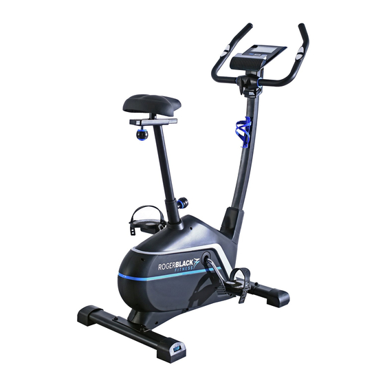
Roger Black Gold Bike
Assembly & User's Instructions-
Important –
Please read these instructions fully before assembly or use
These Instructions contain important information which will help you get best from your
equipment and ensure safe and correct assembly, use and maintenance.
If you need help or have damaged or missing parts, call the Customer Helpline: 0345 600 1714
Please Keep for future reference
402/6004
Issue 1 -4/18/14
Advertisement
Table of Contents

Subscribe to Our Youtube Channel
Related Manuals for Rogerblack Gold Bike


Summary of Contents for Rogerblack Gold Bike
- Page 1 Roger Black Gold Bike Assembly & User’s Instructions- Please Keep for future reference 402/6004 Important – Please read these instructions fully before assembly or use These Instructions contain important information which will help you get best from your equipment and ensure safe and correct assembly, use and maintenance.
-
Page 2: Table Of Contents
Contents Safety Information Components - Parts Components – Fixings Assembly Instructions 5-11 Computer Operation 12-19 Exercising Information 20-23 * Before Starting * Muscle Chart * Warming up and Cooling down 22-23 Care and Maintenance Exploded Parts Diagram Parts List Guarantee... -
Page 3: Safety Information
、 Safety Information Important – Please read fully before assembly or use To reduce the risk of serious injury, read the entire manual before you assemble or operate the Roger Black Bike. In particular, note the following safety precautions: • If the user experiences dizziness, nausea, chest Assembly pain, or other abnormal symptoms stop the workout and seek immediate medical attention. -
Page 4: Components - Parts
Components - Parts If you have damaged or missing parts, please call the Customer Helpline: 0345 600 1714. Please check you have all parts listed below Note: Some of the smaller components may be pre-fitted to larger components. Please check carefully before contacting Argos regarding any missing components. -
Page 5: Components - Fixings
Components - Fixings Please check you have all parts listing below Note: Please check carefully before contacting Argos regarding any missing fixings. × 10mm Spring Washer × × 10mm Washer M10x20mm Allen Bolt × 8mm Spring Washer × 2 × M8x15mm Allen Bolt 8mm Washer ×... -
Page 6: Assembly Instructions
Assembly Instructions Step 1 A. Attach Front Stabilizer (3) to Main Frame (1) using 2 x M10x20MM Allen bolts (17), 2 x10MM Spring Washers (18) and 2 x10MM Washers (19). B. Attach Rear Stabilizer (2) to Main Frame (1) using 2 x M10x20MM Allen bolts (17), 2 x10MM Spring Washers (18) and 2 x10MM Washers (19). - Page 7 Assembly Instructions Step 2 A. Place the Front Post (6) through the Front Post Cover (33). B. Bring the main Wire out from front tube of Main Frame (1) and connect it with the Wire from the bottom of the Front Post (6). C.
- Page 8 Assembly Instructions Step 3 A. Thread the two cables from the computer (13) into the top of the Front Post (6); connect the Wire from Computer (13) to the Wire from Front Post (6). B. Attach the Computer (13) to the Front Post (6) using 4 x M5x8MM Dome Head Philips Bolt (71). Note: Part (71) is pre-assembled.
-
Page 9: St4.2X15Mm Philips Screw
Assembly Instructions Step 4 A. Attach the Handle (7) to the bracket on the Front Post (6), and secure with M10 Lock knob (10). Note: To adjust the position of the handle, turn the lock knob (10) anti clockwise to loose the handle (7) as shown in the diagram, and adjust the handle (7) to your required position, then secure the lock knob (10). - Page 10 Assembly Instructions Step 5 A. Fix the Saddle (11) to the Seat Adjustment Bracket (5) using 3 x 8MM Washers (21) and 3 x 8MM Aircraft Nuts (20). The washers and nuts are pre-assembled on the saddle. B. Attach the Seat Adjustment Bracket (5) to the top of the Seat Post (4) using M10 Lock Knob (9). Note: Move the Saddle (11) forward or backward to a suitable position then tighten M10 Lock Knob (9).
- Page 11 Assembly Instructions Insert the power Charger (68) into the hole on the Main Frame (1) as shown in the diagram. Hold the handle to move the bike as shown in the diagram.
- Page 12 Free area and training area The free area must be at least 0.6m greater than the training area in the directions from which the equipment is accessed. The free area is a place should you need to dismount in an emergency. Where two pieces of equipment are positioned adjacent to each other the value of the free area may be shared.
-
Page 13: Computer Operation
Computer Operation Functions and Operations Display Recovery Mode Enter Start/Stop Key Functions RECOVERY Key: + Key: The recovery function will test your fitness Increases value of selected workout ● ● recovery. To do this, hold the hand pulse parameter. During the workout pressing + will sensors for one minute after which a fitness increase the resistance load. - Page 14 Computer Operation Computer display and specifications 2. SLEEP Mode: After 4 minutes of inactivity, the COMPUTER DISPLAY . computer will enter Sleep Mode. This is an LCD display showing TIME, 3. WAKE UP Mode: Pedal the machine, or press SPEED, DISTANCE, CALORIE, AGE and any key to starter-start the machine.
- Page 15 Computer Operation Choosing your workout program “PROGRAM 1” will be the default display. By pressing the + or - button to scroll, you can scroll through the workout programmes in the following order: PROGRAM 1→ P2→P3→P4→P5→P6→P7→P8→P9→P10→P11→P12→P13(U1) 1. Manual (PROGRAM 1) And 6 Fixed Programmes(P2-P7): ●...
- Page 16 ● Press START/STOP button to begin the body fat test. This requires you to hold the hand pulse sensors continuously until a result is given. Failure to hold the hand pulse sensors throughout the measurement will result in “E4” Error. ●Your results should appear as follows: ●...
- Page 17 ●If your pulse deviates ±5from the set TARGET H.R. then the computer will adjust the resistance automatically to help you workout within your target zone. It will re-check your pulse every 20 seconds and adjust your resistance accordingly. (Note: Each resistance load represents 2 levels of loading) Once one of the target workout parameters reaches zero, the product will beep and you will have reached the end of your workout.
- Page 18 Computer Operation 6. RECOVERY TEST: ● Hold the handle grip sensors with your hands until the pulse window displays pulse value, then press the RECOVERY button within 5 seconds and hold the handle grip sensors with your hands again, after 59 seconds the result will be shown in the following format: Display Figure...
- Page 19 Computer Operation Pre-defined program profile 1. Program 1(MANUAL) 2. Program 2 3. Program 3 4. Program 4 5. Program 5 6. Program 6 7. Program 7 8. Program 8...
-
Page 20: Computer Operation
Computer Operation Pre-defined program profile 9. Program 9 10. Program 10 11. Program 11 12. Program 12 13. Program 13... -
Page 21: Exercising Information
Exercising Information Before starting your exercise How you begin your exercise program depends on your physical condition. If you have been inactive for several years, or are overweight, you must start slowly and increase your time on the equipment; a few minutes per workout increase is advisable. Initially, you may be able to exercise only for a few minutes in your target zone, however, your aerobic fitness will improve over the next six to eight weeks. -
Page 22: Muscle Chart
Exercising Information Muscle Chart Aerobic Exercise Aerobic exercise improves the fitness of your lungs and heart - your body’s most important muscle. Aerobic exercise fitness is promoted by any activity that uses your large muscles (arms, legs, or buttock, for example). Your heart beats quickly and you breathe deeply. -
Page 23: Warming Up And Cooling Down
Exercising Information Warming up and Cooling down exercises Each workout should include the following three parts: 1. A warm-up, consisting of 5 to 10 minutes of stretching and light exercise. A proper warm-up increases your body temperature, heart rate, and circulation in preparation for exercise. 2. -
Page 24: Exercising Information
Exercising Information Calf/Achilles stretch With one leg in front of the other, reach forward and place your hands against a wall. Keep your back leg straight and your back foot flat on the floor. Bend your front leg, lean forward and move your hips toward the wall. -
Page 25: Care And Maintenance
Care and Maintenance Examine the equipment Inspect and tighten all parts Do not attempt to repair periodically in order to detect before using the equipment, this equipment yourself. any damage or wear. Replace defective Should you have any difficulty The safety level of the components immediately and with assembly, operation or equipment can be maintained... -
Page 26: Exploded Parts Diagram
Exploded Parts Diagram... -
Page 27: Parts List
Exploded Parts List Part Description Part Description Main Frame 40 Belt Pulley Rear Stabilizer 41 Crank Front Stabilizer 42 Lock Nut Seat Post 43 C-Shaped Lock Ring Seat Adjustment Bracket 44 Alex Sleeve Front Post 45 Bearing Handle 46 Bearing Chamber M16 Lock Knob 47 Lock Washer M10 Lock Knob... -
Page 28: Guarantee
Guarantee Product Guarantee This product is guaranteed against manufacturing defects from a period of Year This product is guaranteed for twelve months from the date of original purchase. Any defect that arises due to faulty materials or workmanship will either be replaced, refunded or repaired free of charge where possible during this period by the dealer from whom you purchased the unit.
Need help?
Do you have a question about the Gold Bike and is the answer not in the manual?
Questions and answers
Not sure how to plug the adapter in?
Insert the power charger (68) into the hole on the Main Frame (1) as shown in the diagram.
This answer is automatically generated
Can I change from kph to mph on the display screen.