Table of Contents
Advertisement
Available languages
Available languages
ATTACH YOUR RECEIPT HERE
Serial Number _______________ Purchase Date ______________
Questions, problems, missing parts? Before returning to your retailer, call our customer
service department at 1-866-994-4148, 8 a.m. - 6 p.m., EST, Monday - Thursday,
8 a.m. - 5 p.m., EST, Friday.
AB13858
TM
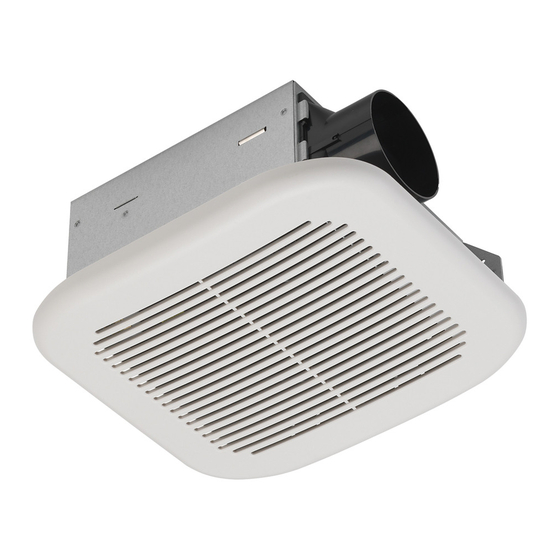
STANDARD
VENTILATION FAN
MODEL #7111-04-L
ITEM #0553457
Français p. 14
Español p. 27
Lowes.com
Advertisement
Chapters
Table of Contents

Related Manuals for Utilitech 7111-04-L


Summary of Contents for Utilitech 7111-04-L
- Page 1 ITEM #0553457 STANDARD VENTILATION FAN MODEL #7111-04-L Français p. 14 Español p. 27 ATTACH YOUR RECEIPT HERE Serial Number _______________ Purchase Date ______________ Questions, problems, missing parts? Before returning to your retailer, call our customer service department at 1-866-994-4148, 8 a.m. - 6 p.m., EST, Monday - Thursday, 8 a.m.
-
Page 2: Table Of Contents
TABLE OF CONTENTS Product Specifications ........................2 Package Contents ..........................3 Safety Information ..........................4 Preparation ............................5 New Construction Assembly Instructions ...................6 Existing Construction Assembly Instructions ..................10 Care and Maintenance ........................11 Troubleshooting ..........................12 Warranty ............................13 PRODUCT SPECIFICATIONS SPECIFICATIONS SPECIFICATIONS Airflow: 70 CFM Power consumption: 13.1 W 120 V, 60 Hz Exhaust fan speed: 1,239 RPM... -
Page 3: Package Contents
PACKAGE CONTENTS PART DESCRIPTION QUANTITY Fan body Grille Duct connector HARDWARE CONTENTS (shown actual size) Short Machine Screw Qty. 3 Lowes.com... -
Page 4: Safety Information
SAFETY INFORMATION Please read and understand this entire manual before attempting to assemble, operate or install the product. Always disconnect the power supply prior to servicing the fan, motor or junction box. Installation work must be carried out by a qualified person(s) in accordance to all local and safety codes including the rules for fire-rated construction. -
Page 5: Preparation
PREPARATION Before beginning assembly of product, make sure all parts are present. Compare parts with package contents list and hardware contents. If any part is missing or damaged, do not attempt to assemble the product. Estimated Assembly Time: 30 minutes Tools Required for Assembly (not included): Hammer, Drill Bits, Flathead Screwdriver, Wire Nuts, Nails, Duct Tape, Phillips Head Screwdriver, Utility Knife Helpful Tools (not included): Electric Drill, Wood Screws... -
Page 6: New Construction Assembly Instructions
NEW CONSTRUCTION ASSEMBLY INSTRUCTIONS CAUTION: MAKE SURE POWER IS SWITCHED OFF AT SERVICE PANEL BEFORE STARTING INSTALLATION. NOTE: UNIT CAN BE MOUNTED IN A CEILING OR WALL. Unplug the fan power unit (1.1). Remove three screws (1.2) that hold the fan motor assembly (1.3) 1. - Page 7 NEW CONSTRUCTION ASSEMBLY INSTRUCTIONS Place the fan housing next to a ceiling joist or wall stud. The fan housing should be level and perpendicular to the joist or stud. Joist or wall stud Mount fan housing to the joist or stud by nailing where Joist or indicated by arrows inside fan housing (4.1).
- Page 8 NEW CONSTRUCTION ASSEMBLY INSTRUCTIONS Install a circular 3 in. duct (not included) and secure it with duct tape or clamps (neither included). Finish ceiling work. Ceiling hole should be aligned with edge of housing of fan (A). 3 in. duct Ceiling Duct tape or clamp...
- Page 9 EXISTING CONSTRUCTION ASSEMBLY INSTRUCTIONS Turn off electricity at breaker box before beginning installation. Remove old fan. 1. 1 Unplug the fan power unit (1.1). Remove three screws (1.2) that hold the fan motor assembly (1.3) in place. Remove fan motor assembly (1.3) from fan housing (1.4).
-
Page 10: Existing Construction Assembly Instructions
EXISTING CONSTRUCTION ASSEMBLY INSTRUCTIONS Install a circular 3 in. duct (not included) and secure it with duct tape or clamps (neither included). 3 in. duct Ceiling Duct tape or clamp Insert fan housing through existing hole in ceiling. The fan housing should be level and perpendicular to the joist or stud. - Page 11 EXISTING CONSTRUCTION ASSEMBLY INSTRUCTIONS Plug back in the power unit (7.1). Replace motor assembly (7.2) using the three screws (7.3) 7. 1 removed in step 1. Pinch mounting springs (8.1) on grille (8.2) and insert into narrow rectangular slots (8.3) inside the fan (A).
-
Page 12: Care And Maintenance
CARE AND MAINTENANCE WARNING: Disconnect power supply before servicing. See SAFETY INFORMATION before proceeding. Routine maintenance should be done at least once a year. • Never use solvents, thinner or harsh chemicals for cleaning the fan. • Do not allow water to enter the motor. •... -
Page 13: Warranty
Inquiries regarding warranty claims can be directed to 1-866-994-4148, 8 a.m. - 6 p.m., EST, Monday - Thursday, 8 a.m. - 5 p.m., EST, Friday. Printed in China Utilitech & UT Design ® is a registered trademark of LF, LLC. All rights reserved. - Page 14 ARTICLE #0553457 VENTILATEUR STANDARD MODÈLE #7111-04-L Des questions, des problèmes, des pièces manquantes? Avant de retourner l’article au détaillant, appelez notre service à la clientèle au 1 866 994-4148, entre 8 h et 18 h (HNE) du lundi au jeudi, ou entre 8 h et 17 h (HNE).
-
Page 15: Caractéristiques Du Produit
TABLE DES MATIÈRES Caractéristiques du produit ......................15 Contenu de l'emballage ........................16 Quincaillerie incluse..........................16 Consignes de sécurité ........................17 Préparation ............................18 Instructions pour l’assemblage dans une nouvelle construction .............19 Instructions pour l’assemblage dans une construction existante ............22 Entretien ............................25 Dépannage ............................25 Garantie ............................26 CARACTÉRISTIQUES DU PRODUIT CARACTÉRISTIQUES CARACTÉRISTIQUES... -
Page 16: Contenu De L'emballage
CONTENU DE L’EMBALLAGE PIÈCE DESCRIPTION QUANTITÉ Corps du ventilateur Grille Raccord pour conduit QUINCAILLERIE INCLUSE (grandeur réelle) Vis à métaux courte Qté. 3 Lowes.com... -
Page 17: Consignes De Sécurité
CONSIGNES DE SÉCURITÉ Assurez-vous de lire et de comprendre l’intégralité du présent manuel avant de tenter d’assembler, d’utiliser ou d’installer l’article. Fermez toujours l’alimentation électrique avant d’effectuer l’entretien du ventilateur, du moteur ou de la boîte de jonction. Les travaux d’installation doivent être effectués par une personne qualifiée, conformément aux codes locaux et de sécurité, y compris les règlements relatifs aux installations pare-feu. -
Page 18: Préparation
PRÉPARATION Avant de commencer l’assemblage du produit, assurez-vous d’avoir toutes les pièces. Comparez le contenu de l’emballage avec la liste des pièces et celle de la quincaillerie incluse. S’il y a des pièces manquantes ou endommagées, ne tentez pas d’assembler l’article. Temps d’assemblage approximatif : 60 minutes. -
Page 19: Instructions Pour L'assemblage Dans Une Nouvelle Construction
INSTRUCTIONS POUR L’ASSEMBLAGE AVANT L’INSTALLATION: Coupez l’alimentation électrique. Consultez toutes les mesures de sécurité. REMARQUE: L’APPAREIL PEUT ÊTRE INSTALLÉ AU PLAFOND OU AU MUR. Débranchez le bloc d’alimentation (1.1) du ventilateur. Retirez les trois vis (1.2) qui retiennent 1. 1 l’ensemble moteur du ventilateur (1.3) en place. - Page 20 INSTRUCTIONS POUR L’ASSEMBLAGE Placez le boîtier du ventilateur près d’une solive de plafond ou d’un montant de cloison. Le boîtier du ventilateur doit être de niveau et perpendiculaire à Solive ou la solive ou au montant. Installez le boîtier de ventilateur sur la solive ou le montant en le clouant aux endroits indiqués par des Solive ou flèches à...
- Page 21 INSTRUCTIONS POUR L’ASSEMBLAGE Installez un conduit circulaire de 3 po (non inclus) et fixez-le à l’aide de ruban à conduits ou d’un collier de serrage (non inclus). Conduit Terminez les travaux au plafond. Vous devez aligner le de 3 po trou du plafond au bord du boîtier de ventilateur (A).
-
Page 22: Instructions Pour L'assemblage Dans Une Construction Existante
CONSTRUCTION EXISTANTE – ACCESSIBLE PAR LE HAUT Avant de commencer l’installation, coupez l’électricité à partir du disjoncteur. Retirez l’ancien ventilateur. 1. 1 Débranchez le bloc d’alimentation (1.1) du ventilateur. Retirez les trois vis (1.2) qui retiennent l’ensemble moteur du ventilateur (1.3) en place. Retirez l’ensemble moteur du ventilateur (1.3) du boîtier du ventilateur (1.4). - Page 23 CONSTRUCTION EXISTANTE – ACCESSIBLE PAR LE HAUT Installez un conduit circulaire de 3 po (non inclus) et fixez-le à l’aide de ruban à conduits ou d’un collier de serrage (non inclus). Conduit de 3 po Ceiling Plafond Ruban adhésif ou pince Insérez le boîtier du ventilateur dans le trou qui se trouve déjà...
- Page 24 CONSTRUCTION EXISTANTE – ACCESSIBLE PAR LE HAUT Rebranchez l’appareil dans le bloc d’alimentation (7.1). Replacez l’ensemble moteur 7. 1 (7.2) à l’aide des trois vis (7.3) retirées à l’étape 1. Pincez les ressorts de fixation (8.1) sur la grille et insérez-les dans les étroites fentes rectangulai- res (8.3) à...
-
Page 25: Entretien
ENTRETIEN AVERTISSEMENT : Coupez l’alimentation électrique avant d’effectuer l’entretien. Lisez les CONSIGNES DE SÉCURITÉ avant de commencer. Vous devez procéder à un entretien au moins une fois par année. • N’utilisez jamais de solvants, ni de diluants, ni tout autre produit chimique fort pour nettoyer le ventilateur. •... -
Page 26: Garantie
Toute réclamation au titre de la garantie peut être faite en téléphonant au 1 866 994-4148, entre 8 h et 18 h (HNE) du lundi au jeudi, ou entre 8 h et 17 h (HNE) le vendredi. Imprimé en Chine Utilitech et le motif UT® sont des marques de commerce déposées de LF, LLC. Tous droits réservés. Lowes.com... - Page 27 ARTÍCULO #0553457 VENTILADOR ESTÁNDAR MODELO #7111-04-L ¿Preguntas, problemas, piezas faltantes? Antes de volver a la tienda, llame a nuestro Departamento de Servicio al Cliente al 1-866-994-4148, de lunes a jueves de 8 a.m. a 6 p.m., y los viernes de 8 a.m. a 5 p.m., hora estándar del Este.
-
Page 28: Especificaciones Del Producto
ÍNDICE Especificaciones del producto ......................28 Contenido del paquete ........................29 Aditamentos............................29 Información de seguridad .........................30 Preparación ............................31 Instrucciones de ensamblaje para una construcción nueva ............32 Instrucciones de ensamblaje para una construcción existente ............35 Cuidado y mantenimiento .........................38 Solución de problemas ........................38 Garantía............................39 ESPECIFICACIONES DEL PRODUCTO ESPECIFICACIONES... -
Page 29: Contenido Del Paquete
CONTENIDO DEL PAQUETE PIEZA DESCRIPCIÓN CANTIDAD Cuerpo del ventilador Rejilla Conector del conducto ADITAMENTOS (se muestran en tamaño real) Tornillo para metal corto Cant. 3 Lowes.com... -
Page 30: Información De Seguridad
INFORMACIÓN DE SEGURIDAD Lea y comprenda completamente este manual antes de intentar ensamblar, usar o instalar el producto. Desconecte siempre el suministro de electricidad antes de realizar tareas de mantenimiento en el ventilador, el motor o la caja de unión. El trabajo de instalación debe estar a cargo de personas calificadas, de acuerdo con todos los códi- gos locales y de seguridad, incluidas las normas para construcción con resistencia al fuego. -
Page 31: Preparación
PREPARACIÓN Antes de comenzar a ensamblar el producto, asegúrese de tener todas las piezas. Compare las piezas con la lista del contenido del paquete y la lista de aditamentos. No intente ensamblar el producto si falta alguna pieza o si estas están dañadas. Tiempo estimado de ensamblaje: 60 minutos Herramientas necesarias para el ensamblaje (no se incluyen): Martillo, destornillador de cabeza plana, empalmes plásticos, clavos, cinta aislante, destornillador Phillips, cuchillo para uso general... -
Page 32: Instrucciones De Ensamblaje Para Una Construcción Nueva
INSTRUCCIONES DE ENSAMBLAJE PARA UNA CONSTRUCCIÓN NUEVA ANTES DE LA INSTALACIÓN: Apague la fuente de alimentación. Revise todas las precauciones de seguridad. NOTA: LA UNIDAD SE PUEDE INSTALAR EN UN TECHO O PARED. Desenchufe la unidad de tomacorriente del ventilador (1.1). - Page 33 INSTRUCCIONES DE ENSAMBLAJE PARA UNA CONSTRUCCIÓN NUEVA Coloque la carcasa del ventilador junto a una vigueta de techo o un montante de pared. La carcasa del ventilador debe estar al nivel de la vigueta o del montante y ser Viga o viga perpendicular a estos.
- Page 34 INSTRUCCIONES DE ENSAMBLAJE PARA UNA CONSTRUCCIÓN NUEVA Instale un conducto circular de 7,62 cm (no incluido) y fíjelo con cinta aislante o abrazaderas (tampoco incluidas). 7,62 cm Finalice el trabajo en el techo. El orificio en el techo conducto debe estar alineado con el borde de la carcasa del ventilador (A).
-
Page 35: Instrucciones De Ensamblaje Para Una Construcción Existente
INSTRUCCIONES DE ENSAMBLAJE PARA UNA CONSTRUCCIÓN EXISTENTE Desconecte la electricidad en la caja del interruptor de circuito antes de comenzar la instalación. Retire el venti- 1. 1 lador antiguo. Desenchufe la unidad de tomacorriente del ventila- dor (1.1). Retire los tres tornillos (1.2) que sostienen el ensamble del motor del ventilador (1.3) en su lugar. - Page 36 INSTRUCCIONES DE ENSAMBLAJE PARA UNA CONSTRUCCIÓN EXISTENTE Instale un conducto circular de 7,62 cm (no incluido) y fíjelo con cinta aislante o abrazaderas (tampoco incluidas). 7,62 cm conducto Ceiling Techo Cinta adhesiva o abrazadera Inserte la carcasa del ventilador (A) a través del orificio existente en el techo.
- Page 37 INSTRUCCIONES DE ENSAMBLAJE PARA UNA CONSTRUCCIÓN EXISTENTE Enchufe nuevamente en la unidad de tomacorriente (7.1). Vuelva a colocar el ensamble del motor (7.2) 7. 1 utilizando los tres tornillos (7.3) retirados en el paso Apriete los resortes de montaje (8.1) en la rejilla (8.2) e inserte en las ranuras rectangulares estre- chas (8.3) al interior del ventilador (A).
-
Page 38: Cuidado Y Mantenimiento
CUIDADO Y MANTENIMIENTO ADVERTENCIA: Desconecte el suministro de electricidad antes de realizar tareas de mantenimiento. Vea la INFORMACIÓN DE SEGURIDAD antes de proceder. Se deber realizar mantenimiento de rutina al menos una vez al año. • Nunca use solventes, disolventes o químicos agresivos para limpiar el ventilador. •... -
Page 39: Garantía
Las preguntas relacionadas con reclamaciones de garantía pueden realizarse al 1-866-994-4148, de lunes a jueves de 8 a.m. a 6 p.m., y los viernes de 8 a.m. a 5 p.m., hora estándar del Este. Impreso en China Utilitech & UT Design ® es una marca registrada de LF, LLC.
Need help?
Do you have a question about the 7111-04-L and is the answer not in the manual?
Questions and answers