Table of Contents
Advertisement
Available languages
Available languages
ATTACH YOUR RECEIPT HERE
Serial Number ___________________________ Purchase Date ___________________________
Questions, problems, missing parts? Before returning to your retailer, call our customer
service department at 1-866-994-4148, 8 a.m. - 8 p.m., EST, Monday - Sunday. You could
also contact us at partsplus@lowes.com or visit www.lowespartsplus.com.
AB1740
TM
READ AND SAVE THESE INSTRUCTIONS
ITEM # 0831383, # 2758193, # 13687108
EASY FIT INSTALL
VENTILATION FAN
WITH LED LIGHT
MODEL 7115-02, 7115-02-BN, 7115-02-CH
Español p. 14
Advertisement
Chapters
Table of Contents

Related Manuals for Utilitech 7115-02-BN


Summary of Contents for Utilitech 7115-02-BN
- Page 1 ITEM # 0831383, # 2758193, # 13687108 EASY FIT INSTALL VENTILATION FAN WITH LED LIGHT MODEL 7115-02, 7115-02-BN, 7115-02-CH Español p. 14 ATTACH YOUR RECEIPT HERE Serial Number ___________________________ Purchase Date ___________________________ Questions, problems, missing parts? Before returning to your retailer, call our customer service department at 1-866-994-4148, 8 a.m.
-
Page 2: Table Of Contents
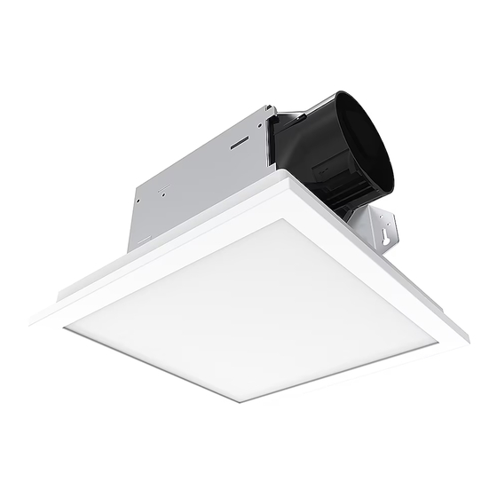
TABLE OF CONTENTS Product Specifications ........................2 Package Contents ..........................3 Safety Information ..........................3 Preparation ............................4 New Construction Installation Instructions..................6 Existing Construction Installation Instructions ..................8 Care and Cleaning..........................12 Troubleshooting ..........................12 Warranty ............................13 PRODUCT SPECIFICATIONS Airflow: 100 CFM Weight: 8.2 lbs. 120 V, 60 Hz LED light color (CCT): 3000K soft white Duct diameter: 4 in. -
Page 3: Package Contents
SAFETY INFORMATION Please read and understand this entire manual before attempting to assemble, operate or install the product. • Always disconnect the power supply prior to servicing the fan, WARNING: To reduce the risk of fire, electric shock, motor or junction box. or injury to persons, observe the following: •... - Page 4 PREPARATION (Continued) Check area above installation location to be sure that wiring can run to the planned location and that duct work can be run and the area is sufficient for proper ventilation. Inspect duct work and wiring before proceeding with installation. Before installation, provide inspection and future maintenance access at a location that will not interfere with installation work.
-
Page 5: New Construction Installation Instructions
NEW CONSTRUCTION INSTALLATION INSTRUCTIONS BEFORE INSTALLATION WARNING: RISK OF ELECTRIC SHOCK! Ensure the electricity to the wires you are working on is shut off. Either remove the fuse or turn off the circuit breaker before removing the existing bath fan or installing the new one. - Page 6 NEW CONSTRUCTION INSTALLATION INSTRUCTIONS (Continued) Mount the fan housing (A) to the joist by inserting wood screws (4.1) (not included) into the holes indicated on the metal tabs of the fan housing (A). Tighten the wood screws (4.1) until the fan housing (A) is firmly secured to the joist.
-
Page 7: Existing Construction Installation Instructions
NEW CONSTRUCTION INSTALLATION INSTRUCTIONS (Continued) Join the connectors for the LED light from the fan housing (A) to the grille (B). The grille (B) must be connected before turning on power to the fan. Attach grille (B) by pinching the mounting springs and inserting them into the narrow rectangular slots in the fan housing (A). - Page 8 EXISTING CONSTRUCTION INSTALLATION INSTRUCTIONS (Continued) Remove existing fan. Measure the opening to ensure it is large enough to accommodate the 7-1/2 in. x 7-1/4 in. dimensions of the new fan housing (A). If this fan is not replacing an old fan, be sure to cut a 7-3/4 in.
- Page 9 EXISTING CONSTRUCTION INSTALLATION INSTRUCTIONS (Continued) Attach the duct connector (C) to the fan housing (A). Remove the three screws (5.1) on the side of the fan housing (A) that hold the fan motor (5.2) in place. With the screws removed, unplug the fan motor (5.2) and pull the fan motor out of the fan housing (A).
- Page 10 EXISTING CONSTRUCTION INSTALLATION INSTRUCTIONS (Continued) Pull the house wires through the hole in the wiring box cover. Using the quick connectors, connect the house wiring from the wall switch to the fan housing Quick connector (A). 14 AWG is the smallest conductor that should be used for branch-circuit wiring.
- Page 11 EXISTING CONSTRUCTION INSTALLATION INSTRUCTIONS (Continued) 10. Mount the fan housing (A) to the joist with three wood screws (10.1) (not included) through the holes in the side of the fan housing (A). Ceiling Joist The fan housing (A) must be installed flush with the ceiling board or the grille mounting springs will not be long enough to insert into the slots inside the fan housing (A).
-
Page 12: Care And Cleaning
EXISTING CONSTRUCTION INSTALLATION INSTRUCTIONS (Continued) 13. Attach grille (B) by pinching the mounting springs and inserting them into the narrow rectangular slots in the fan housing (A). Turn on power source. Test the unit. CARE AND CLEANING CAUTION: Before attempting to clean the fixture, disconnect the power to the fixture by turning the breaker off or removing the fuse from the fuse box. -
Page 13: Warranty
TROUBLESHOOTING (Continued) PROBLEM POSSIBLE CAUSE SOLUTION There is insufficient airflow intake Be sure a door or window is slightly ajar in the room. or open to allow airflow. The fan is not able to draw air out of the room without enough airflow. - Page 14 ARTÍCULO # 0831383, # 2758193, # 13687108 VENTILADOR DE INSTALACIÓN FÁCIL CON LUZ LED MODELO 7115-02, 7115-02-BN, 7115-02-CH ADJUNTE SU RECIBO AQUÍ Número de serie __________________________ Fecha de compra _______________________ ¿Preguntas, problemas, piezas faltantes? Antes de volver a la tienda, llame a nuestro Departamento de Servicio al Cliente al 1-866-994-4148, de lunes a domingos de 8 a.m.
- Page 15 TABLA DE CONTENIDO Especificaciones del producto ......................16 Contenido del paquete ........................15 Información de seguridad .........................16 Preparación............................17 Instrucciones de installación de nueva construcción ...............18 Instrucciones de installación de construcción existentes ..............20 Cuidado y limpieza ...........................25 Solución de problemas ........................25 Garantía............................26 ESPECIFICACIONES DEL PRODUCTO Flujo de aire: 100 CFM Peso: 3,71 kg.
-
Page 16: Preparación
INFORMACIÓN SOBRE SEGURIDAD Por favor, lea y comprenda este manual en su totalidad antes de intentar de ensamblar, operar o instalar el producto. • Siempre desconecte la fuente de alimentación antes de darle ADVERTENCIA: Para reducir el riesgo de incendio, servicio al ventilador, motor o caja eléctrica. - Page 17 PREPARACIÓN (Continuación) Antes de la instalación, proporcione acceso para la inspección y el mantenimiento en un lugar que no interfiera con el trabajo de instalación. La instalacion puede variar dependiendo de cómo se instaló el ventilador anterior. Los suministros necesarios para la instalación de su ventilador de baño no están todos incluidos;...
-
Page 18: Instrucciones De Installación De Nueva Construcción
INSTRUCCIONES DE INSTALACIÓN DE NUEVA CONSTRUCCIÓN PREVIO A LA INSTALACIÓN ADVERTENCIA: ¡RIESGO DE DESCARGA ELECTRICA! Asegurese de cortar el suministro electrico en los cables con los que trabajara. Extraiga los fusibles o apague el cortacircuitos antes de quitar el ventilador de baño existente o instalar uno nuevo. - Page 19 INSTRUCCIONES DE INSTALACIÓN DE NUEVA CONSTRUCCIÓN (Continuación) Fije la caja del ventilador (A) en la viga insertando tornillos para madera (4.1) (no incluido) en los orificios indicados en las pestañas metálicas de la caja del ventilador (A). Apriete los tornillos para madera (4.1) hasta que la caja del ventilador (A) esté...
-
Page 20: Instrucciones De Installación De Construcción Existentes
INSTRUCCIONES DE INSTALACIÓN DE NUEVA CONSTRUCCIÓN (Continuación) Una los conectores para la luz LED de la caja del ventilador (A) a la rejilla (B). La rejilla (B) debe estar conectada antes de encender el ventilador. Fije la rejilla (B) apretando los resortes de montaje e insertándolos en las ranuras rectangulares estrechas en la caja del ventilador (A). - Page 21 INSTRUCCIONES DE INSTALACIÓN DE CONSTRUCCIÓN EXISTENTE (Continuación) Retire el ventilador existente. Mida la abertura para asegurarse de que sea lo suficientemente grande para acomodar las dimensiones de 19,1 cm x 18,4 cm. de la caja del nuevo ventilador (A). Si este ventilador no reemplaza a uno viejo, asegúrese de cortar una abertura de 19,7 cm x 19,1 cm.
- Page 22 INSTRUCCIONES DE INSTALACIÓN DE CONSTRUCCIÓN EXISTENTE (Continuación) Acople el conector del conducto (C) a la caja del ventilador (A). Quite los tres tornillos (5.1) en el lado de la caja del ventilador (A) que hace un agujero al conjunto del motor del ventilador (5.2).
- Page 23 INSTRUCCIONES DE INSTALACIÓN DE CONSTRUCCIÓN EXISTENTE (Continuación) Jale los cables de la casa a través de la tapa la cubierta de la caja de cableado. Usando los conectores rápidos, conecte el cableado de la casa desde el interruptor Conector de pared a la caja del ventilador (A). 14 AWG es el rápido Tapa de la conductor más pequeño que se debe utilizar para el...
- Page 24 INSTRUCCIONES DE INSTALACIÓN DE CONSTRUCCIÓN EXISTENTE (Continuación) 10. Monte la caja del ventilador (A) en la viga con tres tornillos para madera (10.1) (no incluido) a través de los agujeros en el costado de la caja del ventilador (A). La caja del ventilador (A) debe instalarse al ras de la placa del techo o los resortes de montaje de la rejilla no serán lo suficientemente largos como para insertarse en las ranuras dentro de la caja del ventilador (A).
-
Page 25: Cuidado Y Limpieza
INSTRUCCIONES DE INSTALACIÓN DE CONSTRUCCIÓN EXISTENTE (Continuación) 13. Fije la rejilla (B) apretando los resortes de montaje e insertándolos en las ranuras rectangulares estrechas en la caja del ventilador (A). Encienda la fuente de alimentación. Pruebe el ventilador. CUIDADO Y LIMPIEZA PRECAUCIÓN: Antes de limpiar el aparato, desconecte el suministro electrico hacia este apagando el cortacircuitos o extrayendo el fusible de la caja de fusibles. -
Page 26: Garantía
GARANTÍA LIMITADA DE 5 AÑOS Si el ventilador falla debido a un defecto en el material o la mano de obra en cualquier momento durante los primeros CINCO años de poseerlo, elfabricante lo reemplazará sin cargos y con el franqueo pagado a su discreción.
Need help?
Do you have a question about the 7115-02-BN and is the answer not in the manual?
Questions and answers
I bought and installed one of these vents and looking in the website it describes the light as dimmable, how can I dim the light?
The Utilitech 7115-02-BN ventilation fan has a dimmable LED light with a brightness of 1000 lumens. To dim the light, use a compatible dimmer switch. Ensure the switch supports dimmable LED lights for proper functionality.
This answer is automatically generated