Table of Contents

Related Manuals for Hioki SS7012


Summary of Contents for Hioki SS7012
- Page 1 SS7012 Instruction Manual DC SIGNAL SOURCE 99 Washington Street Melrose, MA 02176 Phone 781-665-1400 Toll Free 1-800-517-8431 Visit us at www.TestEquipmentDepot.com Mar. 2015 Revised edition 8 SS7012A981-08 15-03H * 6 0 0 2 8 7 5 1 8 *...
-
Page 2: Table Of Contents
Contents Introduction ................1 Confirming Package Contents ..........2 Safety Information ..............3 Operating Precautions ............7 Chapter 1 Overview Product Overview ..........13 Features ............14 Names and Functions of Parts ......15 Sourcing and Measurement Flowchart ..... 23 Chapter 2 Sourcing, Measurement and Loop test Preparation Supplying Power .......... - Page 3 Scan sourcing ............61 Initializing setting values ........63 When setting value is flashing ......65 Chapter 4 Measurement Measurement Example ........67 Voltage Measurement and Current Measurement ........68 Temperature Measurement .......71 Chapter 5 Loop Test Loop Test Overview ...........75 Testing a Distributor (4-20 mA) ......76 Testing a two-wire transmitter ......79 Chapter 6 Other Function USB Communication Function ......81...
-
Page 4: Introduction
Introduction Introduction Thank you for purchasing the HIOKI Model SS7012 DC Signal Source. To obtain maximum performance from the instrument, please read this manual first, and keep it handy for future refer- ence. -
Page 5: Confirming Package Contents
Hioki representative. Confirm that these contents are provided. SS7012 DC Signal Source (1) 9168 Input Cord (1 set) L9170-10 Test lead (1 set) ... -
Page 6: Safety Information
Safety Information Options 9184 Temperature Probe (reference junction compensation) 9380 Carrying Case (Holds main unit only, soft case) 9782 Carrying Case (Holds options, hard case) 9445-02 AC Adapter (For Japan, US, and Canada) 9445-03 AC Adapter (For EU) ... - Page 7 Safety Information This manual contains information and warnings essential for safe operation of the instrument and for maintaining it in safe operating condition. Before using it, be sure to carefully read the following safety precautions. Safety Symbols In the manual, the symbol indicates particularly important information that the user should read before using the instrument.
- Page 8 Safety Information Symbols for Various Standards WEEE marking: This symbol indicates that the electrical and electronic appliance is put on the EU market after August 13, 2005, and producers of the Member States are required to display it on the appliance under Article 11.2 of Directive 2002/ 96/EC (WEEE).
- Page 9 Safety Information Measurement categories To ensure safe operation of measurement instruments IEC 61010 establishes safety standards for various electrical envi- ronments, categorized as CAT II to CAT IV, and called measure- ment categories. Primary electrical circuits in equipment connected to an AC electrical outlet by a power cord (portable tools, household CAT II appliances, etc.)
-
Page 10: Operating Precautions
Preliminary Checks Before using the instrument for the first time, verify that it oper- ates normally to ensure that no damage occurred during storage or shipping. If you find any damage, contact your dealer or Hioki representative. Instrument Installation Operating temperature and humidity: 0 to 40°C at 80%RH or... - Page 11 Operating Precautions Handling the Instrument The maximum rated voltage between input terminals and ground is 30 VAC/ 60 VDC. Attempting to measure voltages exceeding 30 VAC/ 60 VDC with respect to ground could damage the instrument and result in personal injury. •...
- Page 12 Operating Precautions • When the power is turned off, do not apply voltage to the volt- age input terminals. Doing so may damage the instrument. • To avoid damage to the instrument, protect it from physical shock when transporting and handling. Be especially careful to avoid physical shock from dropping.
- Page 13 Using the instrument in such conditions could cause an electric shock, so contact your dealer or Hioki representative for repair. • Use the 9168 Input Cord with DC 28 V or less.
- Page 14 Operating Precautions Handling the AC Adapter and the Nickel Hydride Batteries • Turn the instrument off before connecting the AC adapter to the instrument and to AC power. • Use only the supplied Model 9445-02 AC Adapter or Model 9445-03 AC Adapter. AC adapter input voltage range is 100 to 240 VAC (with ±10% stability) at 50/60 Hz.
-
Page 15: Chapter 1 Overview
1.1 Product Overview Overview Chapter 1 1.1 Product Overview This instrument is a compact DC signal source (calibrator). It can perform maintenance or loop tests of instrumentation sys- tems and can be operated from a computer via a USB cable. Furthermore, it can calibrate thermometers and measure DC voltage and DC current. -
Page 16: Features
1.2 Features 1.2 Features Source function (p.39) (p.43) Sourcing DC voltage from -25.000 V to +25.000 V (minimum resolution 100 μV), and DC current from -25.000 mA to 25.000 mA (minimum resolution 1 μA). Sourcing thermoelec- tromotive force by setting temperature (thermocouples: K, E, J, T, R, S, B, N;... -
Page 17: Names And Functions Of Parts
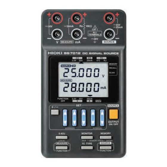
1.3 Names and Functions of Parts 1.3 Names and Functions of Parts Front panel Terminals (p.18) Display (p.19) Operation Keys (p.21) -
Page 18: Power Switch
Turns the power for the instru- ment on or off. (p.33) : Power switch OFF : Power switch ON USB port The SS7012 can communicate with a computer via a USB cable. (p.81) RJ sensor terminal Connect the optional Model 9184 Temperature Probe (reference junction compensation). - Page 19 1.3 Names and Functions of Parts Rear panel Battery cover Open this battery cover to install the LR6 alkaline batteries or the nickel hydride bat- teries. (p.25)
- Page 20 Current input terminal/ Terminal for the standard resistor Current input Inputs current for current measurement function. The SS7012 has built-in input protection fuse. The input resistance of current detection and input protection fuse is about 30 Ω. Standard resistor When current measurement function is off, a 100 Ω...
- Page 21 When this indicator starts flashing, either exchange the batteries or connect the AC adapter. When this indicator is flashing, output cannot be set to ON. (If the SS7012 is outputting when the indica- tor starts flashing, output continues until the output is set to OFF.
- Page 22 1.3 Names and Functions of Parts Indicates that the SS7012 is in remote control mode. The instrument cannot be operated by the keys. Use the LOCAL key to enable key operation. If the USB cable is removed when the is dis- played, the indicator does not turn off.
- Page 23 1.3 Names and Functions of Parts Operation Keys Selects the polarity of the output setting value. 1. Possible to return the display to "00000" in voltage measurement func- tion ([V:2.5V], [V:25V]), or current mea- 0 ADJ/ surement function ([A: 25mA]). LOCAL 2.
- Page 24 1.3 Names and Functions of Parts Sets the thermocouple type in the thermo- TC TYPE electromotive force source function ([TC:0°C], [TC:RJ]). SOURCE Sets the source function for the instru- FUNCTION ment. Switches the output on or off in the source OUTPUT function.
-
Page 25: Sourcing And Measurement Flowchart
1.4 Sourcing and Measurement Flowchart 1.4 Sourcing and Measurement Flowchart 1. Inspections before switching on the power and using the instrument Connecting the AC Adapter (p.27) Installing the Batteries (p.25) Turning the Power On (p.33) Pre-Operation Inspection (p.34) 2. Sourcing Constant voltage (p.39) Constant current (p.39) Thermoelectromotive force (p.43) -
Page 26: Chapter 2 Sourcing, Measurement And Loop Test Preparation
2.1 Supplying Power Sourcing, Measurement and Loop test Preparation Chapter 2 2.1 Supplying Power Installing or Replacing the Batteries • Use the common LR6 alkaline batteries or the common nickel hydride batteries. • To avoid electric shock, turn off the power switch and dis- connect the test leads or input cords from the target device before replacing the batteries. - Page 27 2.1 Supplying Power • Do not use the LR6 alkaline batteries together with the nickel hydride batteries. • To avoid corrosion and damage to this instrument from battery leakage, remove the batteries from the instrument if it is to be stored for a long time.
-
Page 28: Connecting The Ac Adapter (Option)
2.1 Supplying Power Connecting the AC Adapter (Option) • Turn the instrument off before connecting the AC adapter to the instrument and to AC power. • Use only the supplied Model 9445-02 AC Adapter or Model 9445-03 AC Adapter. AC adapter input voltage range is 100 to 240 VAC (with ±10% stability) at 50/60 Hz. -
Page 29: Connecting The Input Cord And The Test Lead
2.2 Connecting the Input Cord and the Test Lead 2.2 Connecting the Input Cord and the Test Lead The SS7012 has voltage input terminal, current input terminal (terminal for the standard resistor) and output terminal. In addition, RJ sensor terminal is provided for temperature mea- surement. - Page 30 2.2 Connecting the Input Cord and the Test Lead Connecting Method Voltage measurement Connect the L9170-10 Test lead to the voltage input ter- minal. Connect the red and black connectors to the + and - input terminals, respectively. Input only voltage to the voltage input terminal. L9170-10 Test lead (red) (black)
- Page 31 2.2 Connecting the Input Cord and the Test Lead Sourcing With the output off, connect the 9168 Input Cord to the output terminal. Connect the red and black connectors to the + and - output terminals, respectively. 9168 Input Cord (red) (black) 0°C check for the 100 Ω...
- Page 32 2.2 Connecting the Input Cord and the Test Lead • This instrument is designed for safe operation only at low voltage. Ensure that no more than 60 V is present between any terminal and ground, and that the potential difference between any two terminals does not exceed 60 V.
- Page 33 2.2 Connecting the Input Cord and the Test Lead • When switching the power on and off, remove the target device from all terminals. Furthermore, always set the output to OFF when connecting or disconnecting the output terminal and target device. In either of these cases, failure to heed this caution may result in damage to the instrument or to the target device.
-
Page 34: Turning The Power On And Off
2.3 Turning the Power On and Off 2.3 Turning the Power On and Off Before turning the instrument on, make sure the supply voltage matches that indicated on the AC adapter. Connec- tion to an improper supply voltage may damage the instru- ment or AC adapter and present an electrical hazard. -
Page 35: Pre-Operation Inspection
2.4 Pre-Operation Inspection Turning Power On Set the power switch to the " " position. When the power switch is on, all settings except memory are initialized to appear initial (ON) screen after LCD display indications are all lit. Turning Power Off Set the power switch to the "... - Page 36 2.4 Pre-Operation Inspection Inspection at power on < When using batteries > When power The batteries may have switched on, does the run out. Replace the bat- screen come on? teries with new ones and then check again. An error is displayed An error is displayed Inspection...
-
Page 37: Chapter 3 Sourcing
Sourcing Chapter 3 Always inspect the instrument before sourcing. See: "2.4 Pre-Operation Inspection" (p.34) Always set the output to OFF when connecting or disconnecting the output terminal and target device. • If the display shows all zeros or is out of the setting range while using the keys, polarity changing is disabled. -
Page 38: Sourcing Example
3.1 Sourcing Example 3.1 Sourcing Example The SS7012 can source constant voltage, constant current, and standard register. Instead of the thermocouple, a voltage corresponding to a spec- ified temperature can be sourced. Constant voltage (CV) (p.39) In [CV:2.5V], constant voltage can be sourced from -2.5 to +2.5 V with the resolution of 100 µV. -
Page 39: Sourcing Constant Voltage And Constant Current
3.2 Sourcing Constant Voltage and Constant Current 3.2 Sourcing Constant Voltage and Constant Current Source DC voltage and DC current. Turn the power switch on. Press the SOURCE FUNCTION the required number of times to set the constant voltage source function ([CV:2.5V], [CV:25V]) or constant cur- rent source function ([CC:25mA]). - Page 40 If the target device has a power source, switch it off and then con- nect the target device to the output terminal of the SS7012. If necessary, switch the power of the target device back on. If the target device doesn’t have a...
- Page 41 3.2 Sourcing Constant Voltage and Constant Current Press the OUTPUT ON/OFF key. is displayed on the screen and the set- ting value is output. However, if the load gets excessive and the setting value cannot be output, the setting val- ue flashes.
- Page 42 3.2 Sourcing Constant Voltage and Constant Current Press the OUTPUT ON/OFF key. is displayed on the screen and the out- put changes to OFF. Never connect this instrument to any voltage sources when sourcing constant voltage. Furthermore, never connect this instrument to an electric current source when sourcing constant current.
-
Page 43: Sourcing Thermoelectromotive Force
3.3 Sourcing Thermoelectromotive Force 3.3 Sourcing Thermoelectromotive Force Outputs voltage according to the setting temperature instead of thermocouples. Thermometers using thermocouples can be calibrated. There are 2 types of thermoelectromotive force source func- tions. The temperature of voltage input terminal (reference junction) of the thermometer can be set to either 0°C or room temperature. - Page 44 3.3 Sourcing Thermoelectromotive Force [TC:RJ] Use when calibrating a thermometer that can com- pensate the temperature of voltage input terminal (reference junction) of the thermometer. As shown in the diagram below, use the [TC:RJ] setting when calibrating a thermometer that compensates the thermoelectromotive force of thermocouples at the reference junction temperature.
- Page 45 3.3 Sourcing Thermoelectromotive Force Press the TC TYPE key to set ther- mocouple ([K], [E], [J], [T], [R], [S], or [N]). Use the keys and key to set the value. The ranges within which the values can be set are as follows: : -174.0°C to 1372.0°C : -220.0°C to 839.0°C : -208.0°C to 1108.0°C...
- Page 46 3.3 Sourcing Thermoelectromotive Force Connect the thermometer to the out- put terminal. The connection methods for [TC:0°C] [TC:RJ] differ. [TC:0°C]: Connect it as indicated in Figure 1. The optional 9184 Temperature Probe may be connected to the RJ sensor terminal or not, without ef- fect.
- Page 47 SS7012 as indicated Figure 3, when using a thermocouple the same type as the thermometer or compensated con- ductors.
- Page 48 3.3 Sourcing Thermoelectromotive Force Press the OUTPUT ON/OFF key. is displayed on the screen and the set- ting value is output. However, if the load gets excessive and the setting value cannot be output, the setting val- ue flashes. If the setting value starts flashing, press the OUTPUT ON/OFF key to set the...
- Page 49 3.3 Sourcing Thermoelectromotive Force • When output in the thermoelectromotive force source function ([TC:RJ]) is on, reference junction compensa- tion will be performed about every 5 seconds, and the output value compensated. • In the thermoelectromotive force source function ([TC:RJ]), when the detected temperature of the optional 9184 Temperature Probe is outside the -25°C to 80°C range, or if connection is incorrect, the mes- sages "rJErr"...
-
Page 50: C Check Of The 100 Ω Resistance Thermometer
3.4 0°C Check of the 100 Ω Resistance Thermometer 3.4 0°C Check of the 100 Ω Resistance Thermometer 100 Ω reference resistor is connected between reference resis- tor terminals, which are the same terminals as the current input terminals. This resistor is for 0°C check of the 100 Ω standard resistance thermometer. -
Page 51: Output Monitor Function
If the target device has a power source, switch it off and then con- nect the target device to the output terminal of the SS7012. If necessary, switch the power of the target device back on. - Page 52 3.5 Output Monitor Function Press the OUTPUT ON/OFF key. is displayed on the screen and the set- ting value is output. However, if the load gets excessive and the setting value cannot be output, the setting val- ue flashes. If the setting value starts flashing, press the OUTPUT ON/OFF key to set the...
- Page 53 3.5 Output Monitor Function Monitor ranges are shown below: [CV:2.5V] Load current : -28.00 mA to 28.00 mA [CV:25V] Load current : -28.00 mA to 28.00 mA [CC:25mA] Load voltage : -28.00 V to 28.00 V [TC:0°C] Reference junction temperature: 0°C [TC:RJ] Reference junction temperature : -25.0°C to 80.0°C...
-
Page 54: Memory Source Function
3.6 Memory Source Function 3.6 Memory Source Function This function records sourcing values and then later recalls them for sourcing. For each source function, up to 20 values can be recorded. In [TC:0°C] and [TC:RJ], the thermocouple type can also be recorded. -
Page 55: Saving Setting Value To Memory
3.6 Memory Source Function Saving setting value to memory Turn the power switch on. Press the SOURCE FUNCTION key to set the source function. Confirm that a does not appear near [MEMORY] the upper right of the screen (normal source mode). If a is displayed, press the MEMORY... - Page 56 3.6 Memory Source Function Use the keys and key to set the value to be sourced. E J T R S B N SOURCE ON MEASURE MONIT OR The five keys correspond to the five columns of the setting. MEASURE MONIT OR Press the ENTER key.
- Page 57 3.6 Memory Source Function If you do not want to save a setting value to the address, press the SKIP key. (Skip setting) "- - - - -" flashes and then the instrument ad- vances automatically to the next address. E J T R S B N SOURCE ON MEASURE MONIT OR...
- Page 58 3.6 Memory Source Function Never switch off the power in memory write mode. It may dam- age the SS7012. • Addresses with skip settings cannot be called by the memory source function. • If the setting value or " " is flashing, the setting - - - - - value or skip setting is being written to memory.
-
Page 59: Recall Sourcing
3.6 Memory Source Function Recall sourcing Press the SOURCE FUNCTION key to set the memory sourcing function. Press the MEMORY key once to set to the recall source mode ([RECALL]). Use the ADDRESS keys (the 2 left- side keys) to set the address to be sourced. - Page 60 3.6 Memory Source Function Press the OUTPUT ON/OFF key. is displayed on the screen and the out- put changes to OFF. Repeat steps Press the MEMORY key twice. Exit recall source mode. • In recall source mode, the output setting value cannot be changed.
-
Page 61: Scan Sourcing
3.6 Memory Source Function Scan sourcing Press the SOURCE FUNCTION key to set the memory sourcing function. Press the MEMORY key twice to set to the scan source mode ([SCAN]). Use the ADDRESS keys (the 2 left- side keys) to set the address to be sourced. - Page 62 3.6 Memory Source Function Press the OUTPUT ON/OFF key. is displayed on the screen and output starts. The setting switches by the specified time in- terval. Press the OUTPUT ON/OFF key. is displayed on the screen and the out- put changes to OFF. Scan sourcing also stops.
-
Page 63: Initializing Setting Values
3.6 Memory Source Function Initializing setting values • Initialize setting values saved to memory. Initialization by source function is possible. Furthermore, all functions can be initialized at same time. • This feature is useful when re-saving settings to memory or when batch initializing the contents of functions that are no longer used. - Page 64 3.6 Memory Source Function Press the SOURCE FUNCTION key to select the function for which settings are to be initialized. After selecting the thermoelectromotive force source function, all functions will be selected: ([CV:2.5V] [CV:25V] [CC:25mA] → → → [TC:0°C], [TC:RJ] →...
-
Page 65: When Setting Value Is Flashing
(Overload) Press the OUTPUT to set the output to OFF. Check the connection of the SS7012 and the target device. If there are unexpected shorts or contact failures, eliminate them. If the setting value is still flashing even after setting output to ON, the performance level of the SS7012 is being exceeded. -
Page 66: Chapter 4 Measurement
"2.4 Pre-Operation Inspection" (p.34) 4.1 Measurement Example The following are the voltages, currents, and temperatures that the SS7012 can measure. Voltage (V) (p.68) In [V:2.5V], measurement is possible from -2.8 to +2.8 V with the res- olution of 100 µV. -
Page 67: Voltage Measurement And Current Measurement
4.2 Voltage Measurement and Current Measurement 4.2 Voltage Measurement and Current Measurement Measure DC voltage or DC current as following procedure. Turn the power switch on. Press the MEASURE FUNCTION the required number of times to set voltage measure function ([V:2.5V], [V:25V]) or current measure function ([A:25mA]). - Page 68 4.2 Voltage Measurement and Current Measurement <For voltage measurement> Connect the test leads to the voltage input terminals for the instrument and short out the ends of the test leads. <For current measurement> Connect the test leads to the current input terminals for the instrument and open the ends of the test leads.
- Page 69 4.2 Voltage Measurement and Current Measurement • f the input is outside the measurement range, the dis- play will indicate "oF". E J T R S B N SOURCE ON OFF MEASURE MONIT OR • The zero adjustment function works only when the measurement value is within ±100 counts.
-
Page 70: Temperature Measurement
4.3 Temperature Measurement 4.3 Temperature Measurement Temperature measurement is possible with the optional 9184 Temperature Probe. Connect the optional 9184 Tempera- ture Probe to the instrument. 9184 Temperature Probe Turn the power switch on. - Page 71 4.3 Temperature Measurement Press the MEASURE FUNCTION 4 times to set the temperature mea- sure function ([TEMP]). At power on, [FUNCTION OFF] is set. Press- ing the MEASURE FUNCTION key changes the setting in the lower shown sequence. [V:2.5V] [V:25V] [A:25mA] →...
- Page 72 4.3 Temperature Measurement • If the temperature measurement function is selected without the optional 9184 Temperature Probe being connected, the message "rJErr" will be displayed. When a Temperature Probe is connected, the error disappears and temperature measurement starts. E J T R S B N SOURCE ON MEASURE MONIT OR...
-
Page 73: Chapter 5 Loop Test
Loop Test Chapter 5 5.1 Loop Test Overview Loop tests can be performed with the SS7012. The loop tests are for systems that include two-wire transmitters and distributors. (See the diagram below). Two-wire transmitters and distributors can be tested using the SS7012. -
Page 74: Testing A Distributor (4-20 Ma)
5.2 Testing a Distributor (4-20 mA) The 4-20 mA current flow of the distributor can be tested by using the SS7012 to sink the 4-20 mA current (a two-wire trans- mitter simulation). For the distributor test, setting values of the source current are minus because the SS7012 sinks current. - Page 75 MEASURE FUNCTION key to set the mea- sure function to [V:25V]. Connect the voltage input terminal of the SS7012 and the input terminal of the instrumentation. Read the voltage of the distributor input terminals and check which terminal has the higher potential.
- Page 76 5.2 Testing a Distributor (4-20 mA) 3. Connect the SS7012 and the distributor and then test. Connect the output terminal of the SS7012 and the input terminal of the distributor as shown in the fig- ure. Be careful of the connection direction. Connect...
-
Page 77: Testing A Two-Wire Transmitter
The two-wire transmitter can be tested by sourcing voltage (volt- age of the power for the transmitter of the distributor) from the SS7012 and monitoring the output current. In this case, it is assumed that the power voltage of the two-wire transmitter is 24 V. - Page 78 5.3 Testing a two-wire transmitter Insert a suitable input into the two-wire transmitter (pressure, temperature, etc.). Read and check the current value from the SS7012 at this time. (Do this for all the inputs that required for testing. The display example is as follows.)
-
Page 79: Chapter 6 Other Function
6.1 USB Communication Function The SS7012 can communicate with a computer. (Remote con- trol) The communication function can set the SS7012, as well as record and save settings and measurements on the computer. To use this function, the optional SS9000 Communica- tion Package is required. -
Page 80: Chapter 7 Specifications
7.1 General Specifications Specifications Chapter 7 7.1 General Specifications Operating Indoors, Pollution degree 2, up to 2000 m (6562-ft.) environment Storage -20 to 50°C (-4 to 122°F) 80%RH or less temperature (non-condensating) and humidity Operating 0 to 40°C (32 to 104°F) 80%RH or less temperature (non-condensating) and humidity... - Page 81 7.1 General Specifications 9445-02 AC Adapter 9445-03 AC Adapter 9 V, 1 A Rated supply voltage: 100 to 240 VAC (Voltage fluctuations of ±10% from the rated supply voltage are taken into account.) Rated supply frequency: 50/60 Hz Power supply Anticipated transient overvoltage: 2500 V Maximum rated power:...
- Page 82 7.1 General Specifications Warm-up time 5 minutes (Battery low warning indicator) Battery voltage When flashing, accuracy cannot be guaranteed. Period of guaranteed 1 year accuracy Source output Bipolar sink-source system method DC constant voltage [CV:2.5V] [CV:25V] Source DC constant current [CC:25mA] functions Thermoelectromotive force...
-
Page 83: Accuracy
7.2 Accuracy 7.2 Accuracy Sourcing Reso- Function Accuracy Remarks lution Constant voltage Maximum output ±0.03% of setting [CV:2.5V] 100 μV ±25 mA or more ±300 μV 0 to ±2.5000 V (sink-source) When shorted, 50 Constant voltage mA or less. ±0.03% of setting [CV:25V] 1 mV Load regulation... - Page 84 7.2 Accuracy Reso- Function Accuracy Remarks lution Thermoelectromo- tive force [TC:RJ] ±0.05% of setting 0.1°C -174.0 to 1372.0°C ±1.0°C ±0.05% of setting Using 9184 0.1°C -220.0 to 839.0°C ±1.0°C Temperature Probe The accuracies list- ±0.05% of setting 0.1°C ed to the left are -208.0 to 1108.0°C ±1.0°C when the monitor...
- Page 85 7.2 Accuracy Measurement % rdg. is the % of the reading Sampling rate: Approx. 1.67 times/s Reso- Function Accuracy Remarks lution Voltage [V:2.5V] 100 μV ±0.03% rdg.±300 μV 0 to ±2.8000 V Voltage [V:25V] After executing a 1 mV ±0.03% rdg.±3 mV 0 to ±28.000 V zero adjustment Current...
-
Page 86: Temperature Coefficient
7.2 Accuracy Temperature coefficient For temperatures other than 23°C±5°C, the following is added. Sourcing [CV:2.5V] : ±0.005% ±30 mV/°C of setting [CV:25V] : ±0.005% ±0.2 mV/°C of setting [CC:25mA] : ±0.005% ±0.2 mA/°C of setting [TC:0°C] ([K], [E], [J], [T], [N]) : ±0.005% ±0.05°C/°C of setting... -
Page 87: Chapter 8 Maintenance And Service
When sending the instrument for repair, remove the batteries and pack carefully to prevent damage in transit. Include cushion- ing material so the instrument cannot move within the package. Be sure to include details of the problem. Hioki cannot be responsible for damage that occurs during shipment. - Page 88 8.1 Troubleshooting Replaceable Parts and Operating Lifetimes Useful life depends on the operating environment and frequency of use. Operation cannot be guaranteed beyond the following periods. For replacement parts, contact your dealer or Hioki rep- resentative. Part Life Electrolytic Capacitors Approx.
- Page 89 8.1 Troubleshooting Before returning for repair Symptom Cause Remedy • Are the batteries cor- Insert the new batteries. See: rectly inserted? "Installing or Replac- Although • Is the useful battery Batteries" have turned on life at an end? (p.25) power •...
-
Page 90: Replacing The Circuit Protection Fuse
Fuse type: 250VF50mAH (φ5.2 × 20 mm) The fuses are fitted on the PCB where the lower case is removed. • The SS7012 has three fuses: two of them are for source func- tion, one for measure function. Fuses are common for all the function. - Page 91 8.2 Replacing the Circuit Protection Fuse Turn off the power switch. Remove the AC adapter, if the AC adapter or some- thing is connected to the AC adapter terminal. Remove the battery cover and then remove all LR6 alkaline batteries or nickel hydride batteries.
-
Page 92: Cleaning
8.3 Cleaning Connect the connector cable to (1). Hook the back of the case into the tracks in the front of the case. Do not allow the connector cable to be pinched by the case. Retighten the two screws removed in step Install the batteries and mount the battery cover. -
Page 93: Error Indication
8.4 Error Indication 8.4 Error Indication Error indication Description Remedial Action Poor temperature Connect the temperature probe connection probe correctly. measurement E J T R S B SOURCE ON OFF temperature at ther- Set the measurement tem- mocouple perature between 0°C and [TC:RJ] is a minus 80°C. -
Page 94: When Calibrating The Instrument
When calibrating the instrument, please ensure that the follow- ing conditions are met. Environment Temperature 23±5°C SS7012 Warm-up time 10 minutes or more To calibrate the instrument, the following devices are necessary. Voltmeter, ammeter, voltage/current generator, insulator and resistor with a sufficient accuracy to... -
Page 95: Index Index
Index Index Numerics 0 ADJ key ......21 Initializing Memory ... 63 0°C Check ......50 INTERVAL keys ....61 24 V Loop Power ....79 Load Current ....53 A:25mA ......68 Load Voltage ....53 AC Adapter Terminal ..16 LOCAL key ....... 21 ADDRESS keys ..59, 61 Loop Test ...... - Page 96 Index Testing a Two-wire Transmitter ..79 Recall Sourcing ....59 Thermocouple ....43 Reference Junction ..43 Thermometer Calibration ..43 Remote Control ....81 Two-wire Transmitter Replacing the Batteries ..25 Simulation ......76 Replacing the Fuse ..94 Resistance Thermometer 50 RJ Sensor Terminal ..
- Page 97 Test Equipment Depot - 800.517.8431 - 99 Washington Street Melrose, MA 02176 TestEquipmentDepot.com...
Need help?
Do you have a question about the SS7012 and is the answer not in the manual?
Questions and answers