
Related Manuals for Hioki 3272


Summary of Contents for Hioki 3272
- Page 1 Instruction Manual 3272 POWER SUPPLY December 2014 Revised edition 12 3272A981-12 14-12H GlobalTestSupply www. .com Find Quality Products Online at: sales@GlobalTestSupply.com...
-
Page 2: Table Of Contents
Contents Introduction Inspection Notes on Safety Precautions Chapter 1 Overview 1.1 Product Overview 1.2 Names of Parts Chapter 2 Specifications 2.1 Product Specifications 2.2 Standards Applying Chapter 3 Measurement Procedure 3.1 Preparations 3.2 Measurement Procedure Chapter 4 Description of Parts 4.1 Power Supply Receptacle 4.2 How to Change the Power Supply Fuse and Change the Power Supply Voltage... - Page 3 ――――――――――――――――――――――――――― Introduction Thank you for purchasing the HIOKI "Model 3272 POWER SUPPLY." To obtain maximum performance from the product, please read this manual first, and keep it handy for future reference. Inspection When you receive the product, inspect it carefully to ensure that no damage occurred during shipping.
-
Page 4: Notes On Safety
――――――――――――――――――――――――――― Notes on Safety WARNING This product is designed to comply with IEC 61010 Safety Standards, and has been thoroughly tested for safety prior to shipment. However, mishandling during use could result in injury or death, as well as damage to the product. Using the product in a way not described in this manual may negate the provided safety features. - Page 5 ――――――――――――――――――――――――――― Safety Symbols This manual contains information and warnings essential for safe operation of the product and for maintaining it in safe operating condition. Before using it, be sure to carefully read the following safety precautions. symbol printed on the product indicates that the user should refer to a corresponding topic in the manual (marked with the...
- Page 6 ――――――――――――――――――――――――――― The following symbols are used in this Instruction Manual to indicate the relative importance of cautions and warnings. Indicates that incorrect operation presents an extreme hazard that could DANGER result in serious injury or death to the user. Indicates that incorrect operation presents a significant hazard that could WARNING result in serious injury or death to the...
- Page 7 ――――――――――――――――――――――――――― Measurement categories To ensure safe operation of measurement products, IEC 61010 establishes safety standards for various electrical environments, categorized as CAT II to CAT IV, and called measurement categories. CAT II : Primary electrical circuits in equipment connected to an AC electrical outlet by a power cord (portable tools, household appliances, etc.) CAT II covers directly measuring electrical outlet receptacles.
-
Page 8: Precautions
Preliminary Check Before using the product for the first time, verify that it operates normally to ensure that no damage occurred during storage or shipping. If you find any damage, contact your dealer or Hioki representative. ―――――――――――――――――――――――― Precautions GlobalTestSupply www. - Page 9 ――――――――――――――――――――――――――― DANGER To avoid accidents, when using other measurementdevices with this one, observe the usage precautions described for each device. When using a measurement instrument that does not provide isolation between its input terminals and chassis or other input terminals, please pay attention to the following points.
- Page 10 viii ――――――――――――――――――――――――――― WARNING To avoid electrical accidents and to maintain the safety specifications of this instrument, connect the power cord only to a 3-contact (two-conductor + ground) outlet. CAUTION To avoid damage to the product, protect it from physical shock when transporting and handling. Be especially careful to avoid physical shock from dropping.
- Page 11 When sending the product for repair, pack carefully to prevent damage in transit. Include cushioning material so the instrument cannot move within the package. Be sure to include details of the problem. Hioki cannot be responsible for damage that occurs during shipment. ―――――――――――――――――――――――― Precautions GlobalTestSupply www.
-
Page 12: Chapter 1 Overview
――――――――――――――――――――――――――― Chapter 1 Overview 1.1 Product Overview This unit is the power supply dedicated to Models 3273-50, 3273, 3274, 3275, and 3276 Clamp on Probe (hereafter referred to as the current probe ), as well as Models CT6700 and CT6701 Current Probe. -
Page 13: Names Of Parts
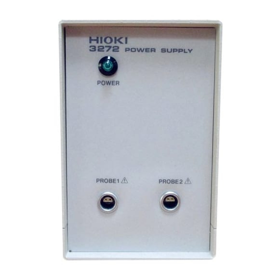
――――――――――――――――――――――――――― 1.2 Names of Parts External view Power indicator Power supply receptacles Front view ―――――――――――――――――――――――― Chapter 1 Overview GlobalTestSupply www. .com Find Quality Products Online at: sales@GlobalTestSupply.com... - Page 14 ――――――――――――――――――――――――――― Power supply connector Fuse holder Power switch Voltage window Grounding terminal Rear view ―――――――――――――――――――――――― Chapter 1 Overview GlobalTestSupply www. .com Find Quality Products Online at: sales@GlobalTestSupply.com...
-
Page 15: Chapter 2 Specifications
――――――――――――――――――――――――――― Chapter 2 Specifications 2.1 Product Specifications Compatible 3273-50, 3273, 3274, 3275, 3276 Clamp sensors On Probe and CT6700, CT6701 Current Probe Number of power supply connectors Output voltage 12 V 0.5 V Rated output 600 mA (sum total of all channels and current all output voltages) Ripple voltage... -
Page 16: Standards Applying
――――――――――――――――――――――――――― Storage 10 to 50 (14 to 122 ), 80% RH or temperature and less (no condensation) humidity range Location for use Indoor,altitude up to 2000 m (6562 feet) Rated supply 100 V AC (120, 220, and 240 V require voltage specification) (Voltage fluctuation of 10% from the rated supply voltage are... - Page 17 ――――――――――――――――――――――――――― 3.1 Preparations DANGER To avoid accidents, when using other measurementdevices with this one, observe the usage precautions described for each device. When using a measurement instrument that does not provide isolation between its input terminals and chassis or other input terminals, please pay attention to the following points.
-
Page 18: Chapter 3 Measurement Procedure
(2) Connect the power plug of the sensor to be used to the power receptacle of the 3272. Turn the 3272 power switch on, and check that the front panel power indicator lights. 3.2 Measurement Procedure See the 3273-50, 3273, 3274, 3275, 3276, CT6700 or CT6701 instruction manual. - Page 19 ――――――――――――――――――――――――――― AC(f=50Hz) (1) 3273-50 current (A) AC(f=50Hz) (2) 3274 current (A) AC(f=50Hz) 100 200 300 400 500 600 700 (3) 3275 current (A) ―――――――――――――――――――――――― Chapter 3 Measurement Procedure GlobalTestSupply www. .com Find Quality Products Online at: sales@GlobalTestSupply.com...
- Page 20 ――――――――――――――――――――――――――― AC(f=50Hz) (4) 3276 current (A) AC(f=50Hz) (5) 3273 current (A) ―――――――――――――――――――――――― Chapter 3 Measurement Procedure GlobalTestSupply www. .com Find Quality Products Online at: sales@GlobalTestSupply.com...
- Page 21 ――――――――――――――――――――――――――― (6) CT6700, CT6701 current (A) Fig.1 Current consumption* vs. current to be measured(typical) *The sum total of a positive and negative current consumption ―――――――――――――――――――――――― Chapter 3 Measurement Procedure GlobalTestSupply www. .com Find Quality Products Online at: sales@GlobalTestSupply.com...
-
Page 22: Chapter 4 Description Of Parts
4.2 How to Change the Power Supply Fuse and Change the Power Supply Voltage The power supply fuse for the 3272 unit, and the power supply voltage selector, are housed in the power input socket on the rear panel. ――――――――――――――――――――――――... - Page 23 ――――――――――――――――――――――――――― WARNING To avoid electric shock, turn off the power switch and disconnect the current probe before replacing the fuse. Replace the fuse only with one of the specified characteristics and voltage and current ratings. Never use unspecified fuses and never use the product after the fuse holder has shorted.
- Page 24 ――――――――――――――――――――――――――― setting appears in the voltage window as shown in the figure. Then recheck the setting value shown in the voltage window. (The voltage display is upside down and backwards.). (2) Change the power supply fuse for a new one whose rating and specification are appropriate for the new power supply setting.
- Page 25 ――――――――――――――――――――――――――― When altering the power supply voltage setting: Fuse holder Voltage selector Remove the voltage selector, rotate it so that the figures which will appear in the voltage window represent the voltage of the power supply which will now be used, and then replace When changing the power supply fuse:...
- Page 26 2. Malfunctions that are detennined by Hioki to have occurred under one or more of the following conditions are considered to be outside the scope of warranty coverage, even if the event in question occurs during the warranty period: a.
Need help?
Do you have a question about the 3272 and is the answer not in the manual?
Questions and answers