
Related Manuals for red lion TCU


Summary of Contents for red lion TCU
- Page 1 THE TEMPERATURE CONTROLLER MODEL TCU INSTRUCTION MANUAL Phone: 800.894.0412 - Fax: 888.723.4773 - Web: www.clrwtr.com - Email: info@clrwtr.com...
- Page 2 The TCU unit, which you have purchased, has the same high quality workmanship and advanced technological capabilities that have made Red Lion Controls the leader in today’s industrial market.
-
Page 3: Table Of Contents
Table of Contents GENERAL DESCRIPTION · · · · · · · · · · · · · · · · · · · · · · · · · · · · · · · · · · · · · · · · · · · · · · · · · · · · · · · 1 SAFETY SUMMARY ·... - Page 4 Configuration Of Parameters · · · · · · · · · · · · · · · · · · · · · · · · · · · · · · · · · · · · · · · · · · · · · · · · · · 15 Parameter Entry ·...
- Page 5 Lower Display Lockouts (SP, OP, HCur, IN-2, dEv, UdSP) · · · · · · · · · · · · · · · · · · · · · · · · · 28 Protected Mode Lockouts (Code, PID, PID2, rtbS & AL) · · · · · · · · · · · · · · · · · · · · · · · · · · · 28 Hidden Mode Lockouts (ALrS, trnF, tUNE and SPSL) ·...
- Page 6 Valve Position Deadband (VPdb) (Position Mode) · · · · · · · · · · · · · · · · · · · · · · · · · · · · · · · · 39 Valve Fail Time Alarm (VFAL) (Position Mode) · · · · · · · · · · · · · · · · · · · · · · · · · · · · · · · · · · 39 Valve Motor Open Time And Valve Motor Close Time (VOPt, VCLt) (Velocity mode) ·...
- Page 7 External Cascade Control · · · · · · · · · · · · · · · · · · · · · · · · · · · · · · · · · · · · · · · · · · · · · · · · · · 61 Internal Cascade Control ·...
- Page 8 Calibration · · · · · · · · · · · · · · · · · · · · · · · · · · · · · · · · · · · · · · · · · · · · · · · · · · · · · · · · · · · · · · · · 84 Configure Step 9 - Factory Service Operations (9-Fs) ·...
-
Page 9: General Description
GENERAL DESCRIPTION The TCU Controller accepts signals from a variety of temperature sensors The optional Heater Current Monitor serves as a digital ammeter for heater (thermocouple or RTD elements), precisely displays the process temperature, current monitoring. Used with current transformer accessory (CT005001), and provides an accurate output control signal (time proportional, linear, or this display is integrated within the controller. -
Page 10: Safety Summary
Rate, etc. can be interrogated or changed, by sending the proper command Do not use the TCU to directly command motors, valves, or other actuators code via serial communications. Alarm output(s) may also be reset via the not equipped with safeguards. -
Page 11: Installation & Connections
NEMA 4X/IP65 Unit Installation The unit should be installed in a location that does not exceed the maximum The optional NEMA 4X/IP65 TCU Controller is designed to provide a operating temperature and provides good air circulation. Placing the unit near watertight seal in panels with a minimum thickness of 1/8 inch. - Page 12 Figure 1, Panel Installation & Removal Phone: 800.894.0412 - Fax: 888.723.4773 - Web: www.clrwtr.com - Email: info@clrwtr.com...
-
Page 13: Unit Removal Procedure
Unit Removal Procedure To remove a NEMA 4X/IP65 or standard unit from the panel, first unscrew and remove the panel latch screws. Insert flat blade screwdrivers between the latch and the case on the top and bottom of the unit, so that the latches disengage from the grooves in the case. -
Page 14: Output Modules
Output Modules Typical Connections The main control, optional Alarm, optional Cooling output and optional Valve Position control output sockets must be fitted with the appropriate output module. Output modules are shipped separately and must be installed by the user. Output Module Restrictions Figure 3, Relay Module With some models, the Alarm outputs and Valve Position outputs share the same common terminal. -
Page 15: Select Input Sensor Type
Figure 5, Triac Module Triac: Type: Isolated, Zero Crossing Detection. Rating: Voltage: 120/240 VAC. Max. Load Current: 1 amp @ 35°C 0.75 amp @ 50°C Min. Load Current: 10 mA Off State Leakage Current: 7 mA maximum @ 60 Hz Operating Frequency: 20 to 400 Hz Protection:... -
Page 16: Emc Installation Guidelines
EMC INSTALLATION GUIDELINES 5. In extremely high EMI environments, the use of external EMI suppression devices, such as ferrite suppression cores, is effective. Install them on Although this unit is designed with a high degree of immunity to Signal and Control cables as close to the unit as possible. Loop the cable ElectroMagnetic Interference (EMI), proper installation and wiring methods through the core several times or use multiple cores on each cable for must be followed to ensure compatibility in each application. -
Page 17: Signal Wiring
Signal Wiring When connecting the thermocouple or RTD leads, be certain that the connections are clean and tight, refer to Figures 7 and 8 for terminal connections. If the thermocouple probe cannot be connected directly to the controller, thermocouple wire or thermocouple extension-grade wire must be used to extend the connection points (copper wire does not work). -
Page 18: Valve Positioner Wiring
For Velocity mode valve control the slidewire feedback inputs are not necessary. In some cases, it may be desirable to have an independent valve position indicator. Red Lion Controls Model IMD1 can be wired in parallel with the slidewire input’s Wiper and Comm. -
Page 19: Heater Current Monitor Wiring
Heater Current Monitor Wiring AC Power Wiring Units with Heater Current Monitor option have two input terminals to Primary AC power is connected to the separate two position terminal block receive the output directly from a 100 mA current transformer. labeled AC. -
Page 20: Front Panel Description
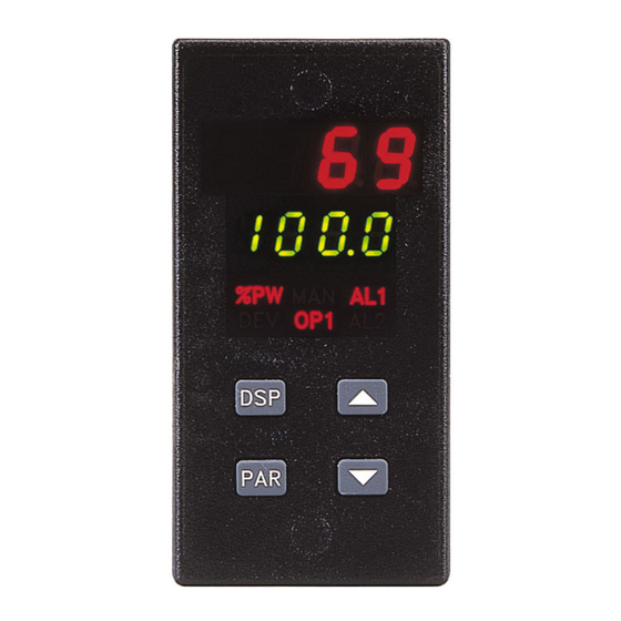
FRONT PANEL DESCRIPTION The front panel bezel material is flame and scratch resistant, tinted plastic. An optional NEMA 4X/IP65 bezel version is available that meets NEMA 4 X/IP65 requirements, when properly installed. There are two 4-digit LED displays, a red upper Main Display and a lower green Secondary Display. -
Page 21: Operation Overview
OPERATION OVERVIEW Controller Power-up D) Use values based on control loop experience, calculated values or values Upon applying power, the controller delays control action and temperature from a similar process. indication for five seconds to perform several self-diagnostic tests and If the controller is a replacement, the PID settings from the unit being display basic controller information. -
Page 22: Remote And Local Setpoint Operation
Remote And Local Setpoint Operation The controller setpoint mode can be switched between Local Setpoint operation and Remote Setpoint operation. In the Hidden Function Mode, the “SPSL” parameter allows the operator to select the desired setpoint operating mode. To allow front panel switching between setpoint modes, program the setpoint select parameter (SPSL) to “Enbl”... -
Page 23: Configuration Of Parameters
Configuration Of Parameters Operation and configuration of the controller is divided into five distinct operational/programming modes to simplify the operation of the controller: As supplied from the factory, the controller parameters have been Normal Display Mode, Unprotected Parameter Mode, Protected Parameter programmed to the values listed in the Programming Quick Reference Mode, Hidden Function Mode, and Configuration Parameter Modules. -
Page 24: Parameter Entry
Parameter Entry Normal Display Mode The PAR button is used to select the desired parameter. To modify the In the normal display mode, the process temperature is always displayed in parameter setting use the UP and DOWN buttons. Press PAR to enter the new the main display. -
Page 25: Unprotected Parameter Mode
UNPROTECTED PARAMETER MODE Unprotected Parameter Mode Reference Table The Unprotected Parameter Mode is accessed by pressing the PAR button from the normal display mode with program disable inactive. In this mode, Range and Description/ the operator has access to the list of the most commonly modified controller Display Parameter Units (Factory... - Page 26 Range and Description/ Display Parameter Units (Factory Comments Setting Value) dt-2 Derivative 0 to 9999 sec. 0 is off. This parameter does not Time #2 appear if proportional band #2 = (Secondary) 0.0%. Second Analog Input models only. SP-2 Internal -999 to 9999 Second Analog Input models Cascade...
-
Page 27: Protected Parameter Mode Reference Table
PROTECTED PARAMETER MODE The Protected Parameter Mode is accessed from the normal display mode module, access to the unprotected parameter mode and hence, the by pressing the PAR button with program disable active. In this mode, the configuration parameter modules is possible. The controller returns to the operator has access to the list of the most commonly modified controller normal display mode if the unprotected mode and configuration modules parameters that have been “unlocked”... -
Page 28: Front Panel Program Disable
Front Panel Program Disable Models With Program Disable There are several ways to limit the programming of parameters from the front panel buttons. The settings of the parameters in the Lockout Module, the Program Disable Code Number Description code number entered, and the state and/or function programmed for the User Inactive Full access to all modes and Input (Terminal #7) affect front panel access. -
Page 29: Hidden Function Mode
HIDDEN FUNCTION MODE Hidden Function Mode Reference Table The Hidden Function Mode is only accessible from the normal display mode by pressing and holding the PAR button for three seconds. These Range and Units Description/ Display Parameter functions must be unlocked in Configuration Module #3. Factory settings are (Factory Setting Value) Comments locked. -
Page 30: Configuration Parameter Modules
CONFIGURATION PARAMETER MODULES Accessible from the unprotected parameter mode, the configuration Temperature Scale (SCAL) parameter modules allow the operator access to the controller’s fundamental Select either degrees Fahrenheit (F) or degrees Celsius (C). If changed, be set-up parameters. There are nine possible configuration stages that can be sure to check All parameters. -
Page 31: Input Sensor Correction Constants (Span & Shft)
Input Sensor Correction Constants (SPAN & SHFt) Setpoint Ramp Rate (SPrP) If the controller temperature disagrees with a reference temperature The setpoint can be programmed to ramp independent of the controller’s instrument or if the temperature sensor has a known calibration, the controller display resolution. -
Page 32: User Input
On models equipped with Second Analog Input, configured as Remote SPSL - Select Local or Remote Setpoint. On models equipped with Second Setpoint, this parameter may be used to establish a maximum rate of change of Analog Input, configured as Remote Setpoint, a negative transition the Remote Setpoint reading. -
Page 33: Output Module (2-Op)
Output Module (2-OP) Output Power Limits (OPLO & OPHI) Enter the safe output power limits for the process. These parameters may The controller has parameters that affect how the main control output also be used to limit the minimum and maximum controller power due to (OP1) responds to temperature changes and sensor failures. -
Page 34: Output Power Dampening (Opdp)
Output Power Dampening (OPdP) Auto-Tune Dampening Code (tcod) The output power calculated by the PID controller can be dampened Prior to invoking Auto-Tune, the dampening code should be set to achieve (filtered) to reduce the controller output activity. Those processes with high the desired dampening level under PID control. -
Page 35: Linear Dc Analog Output (Anas, Anlo, Anhi, Andb, Anut) (Optional)
Linear DC Analog Output (ANAS, ANLO, ANHI, ANdb, ANUt) Example: Chart Record Process Display Value (0 to 10 VDC): (Optional) The process range is 300-700. Programming 300 for ANLO (0 VDC The Linear DC output can be programmed to transmit one of the following value) and 700 for ANHI (10 VDC value) yields full scale deflection for a controller parameters: chart recorder (0 to 10 VDC). -
Page 36: Phone: 800.894.0412 - Fax: 888.723.4773 - Web: Www.clrwtr.com - Email: Info@Clrwtr.com Lockouts Module (3-Lc)
Lockouts Module (3-LC) The code number allows access to the unprotected mode. To enter the unprotected mode from the protected mode, the code number entered must The controller can be programmed to limit operator access to various Front Panel Program Disable, match the code number entered here. -
Page 37: Alarm Module (4-Al) (Optional)
2. The main control output (OP1) is “OFF” and the heater current reading is recommended. Red Lion Controls model IMT (thermocouple) or model IMR above 10% of the alarm value. (RTD) units may be used for this purpose. The indicators should have input This alarm action indicates a current leakage through the final actuator. - Page 38 The alarm triggers under the two following conditions: 1. The valve slidewire feedback position does not match the controller output power (within the valve position deadband) after the valve fail time has expired. The alarm indicates that the valve cannot be properly positioned due to a malfunction of the valve or valve positioner.
- Page 39 Phone: 800.894.0412 - Fax: 888.723.4773 - Web: www.clrwtr.com - Email: info@clrwtr.com...
- Page 40 Phone: 800.894.0412 - Fax: 888.723.4773 - Web: www.clrwtr.com - Email: info@clrwtr.com...
-
Page 41: Alarm Reset (Rst1, Rst2)
Alarm Reset (rSt1, rSt2) Alarm Standby Delay (Stb1, Stb2) Each alarm reset action may be independently configured. The alarm(s) may be independently configured to exhibit a power-on, LAtC - Latching standby delay which suppresses the alarm output from turning “ON” until the Auto - Automatic temperature first stabilizes outside the alarm region. -
Page 42: Alarm Hysteresis (Ahys)
Alarm Hysteresis (AHYS) Heat-Cool Overlap/Deadband (db-2) The alarm(s) values have a programmable hysteresis band to prevent alarm This parameter defines the area in which both heating and cooling are output chatter near the alarm trigger temperature. The hysteresis value should active (negative value) or the deadband area between the bands (positive be set to eliminate this effect. -
Page 43: Serial Communications Module (6-Sc) (Optional)
Serial Communications Module (6-SC) (Optional) When communicating with a TCU unit via the serial port, the data formats of both units must be identical. A print operation occurs when the user input, programmed for the print request function is activated, when a “P” command is sent via the serial communications port, or after the time expires for the automatic print rate, if enabled. -
Page 44: Print Options (Popt)
Print Options (PoPt) Operation mode (OPEr) Selecting YES for the print options allows the operator to scroll through The Second Analog Input must be configured for either Remote Setpoint the available options using the PAR button. The up and down arrow keys Operation or Internal Cascade Operation (single controller cascade). -
Page 45: Decimal Point Position (Dpt2)
Square Root Linearization (root) (Cont’d) Before programming the indicator, organize all the data for the As a result of the scaling and square root linearization, the following programming steps to avoid confusion. represents the readings at various inputs: To scale the indicator, two signal values and two display values that correspond to the signal values must be known. -
Page 46: Local/Remote Setpoint Transfer Modes (Sptr)
Local/Remote Setpoint Transfer Modes (SPtr) Valve Positioner Module (8-VP) When switching from/to Local or Remote Setpoint, the response of the The Valve Positioner controller must be configured to operate in either controller can be programmed to act in a variety of ways. Position Mode or Velocity Mode. -
Page 47: Valve Update Time (Vudt) (Position And Velocity Mode)
Valve Position 1 And Valve Position 2 (VPS1, VPS2) (Cont’d) Valve Motor Open Time And Valve Motor Close Time (VOPt, VCLt) (Velocity mode) 3) Measure the resistance of the open and closed positions and divide by the total slidewire resistance to yield percentage values. Directly key-in the For velocity mode control, the valve motor open transit time (VOPt) and percentage values. -
Page 48: Reference Table: Configuration Parameter Module
Reference Table: Configuration Parameter Module Configure Module 1 - Input Parameters (1-IN) Range and Units Range and Units Description/ Description/ Display Parameter (Factory Setting Display Parameter (Factory Setting Comments Comments Value) Value) SPHI Upper limit -999 to 9999 Set high limit above tYPE Input type tc-t - Type T TC... -
Page 49: Configure Module 2 - Output Parameters (2-Op)
Configure Module 2 - Output Parameters (2-OP) Range and Units Range and Units Description/ Description/ Display Parameter (Factory Setting Display Parameter (Factory Setting Comments Comments Value) Value) ANAS Linear DC output OP -% output This parameter CYCt Cycle time 0 to 250 seconds 0 turns OP1 off. -
Page 50: Configure Module 3 - Lockout Parameters (3-Lc)
Configure Module 3 - Lockout Parameters (3-LC) Range and Units Range and Units Description/ Description/ Display Parameter (Factory Setting Display Parameter (Factory Setting Comments Comments Value) Value) rtbS Remote Setpoint LOC - lockout Remote Setpoint Ratio Setpoint access LOC - lockout Determines access to Ratio &... -
Page 51: Configure Module 4 - Alarms (4-Al)
Configure Module 4 - Alarms (4-AL) Unit returns to configuration access point if alarm(s) are not installed. Range and Units Range and Units Description/ Description/ Display Parameter (Factory Setting Display Parameter (Factory Setting Comments Comments Value) Value) Act2 Alarm 2 operation A-HI - absolute high If changed, check Act1... -
Page 52: Configure Module 5 - Cooling Parameters (5-O2)
Configure Module 5 - Cooling Parameters (5-O2) Unit returns to configuration access point if cooling option is not installed. Range and Units Description/ Display Parameter (Factory Setting Comments Value) CYC2 Cooling output cycle 0 to 250 sec 0 turns OP2 off. time GAN2 Relative cooling... -
Page 53: Configure Module 6 - Serial Communications (6-Sc)
Configure Module 6 - Serial Communications (6-SC) Unit returns to configuration access point if RS485 serial option is not installed. Range and Units Range and Units Description/ Description/ Display Parameter (Factory Setting Display Parameter (Factory Setting Comments Comments Value) Value) bAUd Baud rate 300 to 9600... -
Page 54: Configure Module 7 - Second Analog Input (7-2N)
Configure Module 7 - Second Analog Input (7-2N) Configure Module 8 - Valve Positioner (8-VP) Unit returns to configuration access point if Second Analog Input option is Unit returns to configuration access point if Valve Positioner option is not not installed. installed. -
Page 55: Configure Module 9 - Factory Service Operations (9-Fs)
Configure Module 9 - Factory Service Operations (9-FS) Range and Units Description/ Display Parameter (Factory Setting Comments Value) Code Enter factory service 48 - Calibrate Refer to Calibration function code. instrument Section for details. 66 - Reset parameters to factory settings Phone: 800.894.0412 - Fax: 888.723.4773 - Web: www.clrwtr.com - Email: info@clrwtr.com... -
Page 56: Rs485 Serial Communications Interface
When used with a location. Typical devices that are connected to a TCU unit are a printer, a terminal or host computer and only one unit is employed, an address of zero terminal, a programmable controller, or a host computer. -
Page 57: Output Status
2 - Manual front panel. The TCU accepts the decimal point, however it does not (User) interpret them in any way. Leading zeros can be eliminated, but all trailing... - Page 58 It is recommended that a “Transmit Value” command follow a “Change Value” Command. If this is done, the reception of the data can provide a If illegal commands or characters are sent to the TCU, the string must be timing reference for sending another command and insures that the change re-transmitted.
-
Page 59: Receiving Data
Mnemonics Sent 1 SET 525F<CR><LF>100 - 200 msec Data is transmitted from the TCU when a “T” Transmit Value or a “P” 1 PWR 20%<SP><CR><LF><SP><CR><LF>100 - 200 msec Transmit Print Options command is sent to the unit via the serial port. Data is also transmitted when the User Input, programmed for the Print Request -673.5<CR><LF>100 - 200 msec... - Page 60 A print-out from a TCU unit with an address of 1 and all print options selected is shown below: 1 TMP 500F 1 SET 525F 1 PWR 20.0% 1 PBD 4.0% 1 INT 120S 1 DER 30S 1 AL1 600F...
-
Page 61: Terminal Emulation Program For Ibm Pc
PC BASIC. The program may need to be modified if using a 110 IF LOC(1) = 0 THEN 110 different BASIC interpreter. Set up the TCU for a baud rate of 9600. When the 120 B$ = INPUT$(1, #1) program is running, commands can be typed in from the keyboard as shown in 130 IF B$ = CHR$(10) THEN 160"... -
Page 62: Serial Connections
The signal ground is required if the equipment does not have internal bias resistors connected to the RS485 transceiver lines. The signal ground is connected at the RS485 common of only one TCU unit to the RS485 equipment. If necessary, the shield can be used as the signal ground. - Page 63 When more than one controller is on the line, each TX EN terminal is connected to the transmit disable pin of the GCM422 module. Only one TCU can have the print function activated at a time, otherwise line collision will occur resulting in a garbled print-out.
-
Page 64: Connecting To A Host Terminal
Connecting To A Host Terminal Troubleshooting Serial Communications Six TCU units are used to control a process in a plant. The TCU units are If problems are encountered when interfacing the TCU(s) and host device located at the proper location to optimize the process. A communication line or printer, the following check list can be used to help find a solution. -
Page 65: Heater Current Monitor Option
HEATER CURRENT MONITOR OPTION This option allows monitoring of heater element current controlled by the TCU via the main output OP1. The actual heater current is viewed in the lower display. This is useful in determining how much the heater element has aged, if the element open circuited or if the element has a ground fault. -
Page 66: Valve Position Option
In Position mode valve control, the slidewire resistance, representing the mode valve control parameters of the TCU: valve position, is measured by the TCU and scaled internally to equal 0% to 100%. The scaled valve position is compared with the output power to VPS1 20.0... -
Page 67: Velocity Mode Valve Control
TCU with Valve Positioner option. The TCU maintains the output power directly, as in Position mode. Subsequently, as long as there constant hot water temperature by controlling the position of the valve. No is process error, the controller activates the motor control outputs slidewire feedback is used. -
Page 68: Second Analog Input Option
The temperature of the reacting agent is manually controlled, and the setpoint of the adhesive must track that of the reacting agent. A TCU with Remote Setpoint with a Ratio value of 1.500 (rtio) is used to regulate the adhesive temperature. A temperature transmitter from the blending agent vat is used to generate the Remote Setpoint signal. -
Page 69: External Cascade Control
Parameter response time of the Primary process. Additionally, Setpoint Limit Low and Example: A TCU (temperature input) and PCU (process input) are used in an Setpoint Limit High parameters (SPLO, SPHI) may be used to constrain the External Cascade arrangement to regulate the temperature of a large dye vat. -
Page 70: Internal Cascade Control
Internal Cascade Control Example: A TCU with Second Analog Input is used in an Internal Cascade The Internal Cascade control mode of the TCU embodies the function of arrangement to regulate the temperature of a large dye vat. The Second two Cascade controllers into a single unit. -
Page 71: Pid Control
PID CONTROL Proportional Band Integral Time Proportional band is defined as the “band” of temperature the process Integral time is defined as the time, in seconds, in which the output due to changes to cause the percent output power to change from 0% to 100%. The integral action alone equals the output due to proportional action with a band may or may not be centered about the setpoint value depending upon the constant process error. -
Page 72: Derivative Time
Derivative Time Output Power Offset (Manual Reset) Derivative time is defined as the time, in seconds, in which the output due If the integral time is set to zero (automatic reset is off), it may be necessary to proportional action alone equals the output due to derivative action with a to modify the output power to eliminate errors in the steady state. - Page 73 PID Adjustments (Cont’d) Figure 35, Process Response Extremes Phone: 800.894.0412 - Fax: 888.723.4773 - Web: www.clrwtr.com - Email: info@clrwtr.com...
-
Page 74: On/Off Control
ON/OFF CONTROL The controller operates in the ON/OFF control mode by setting the proportional band = 0.0%. The ON/OFF control hysteresis band (CHYS) parameter eliminates output chatter around setpoint. For heat/cool systems, the cooling output can also be used in the ON/OFF control by setting the relative gain = 0.0 (GAN2). - Page 75 ON/OFF and PID control can be used for the heat and cool outputs in several combinations. The following lists the valid control modes: OP1 & OP2 VALID CONTROL MODES MANUAL MODE OUTPUT POWER MODE MODE STATE STATE RANGE — 0% to +100% OP1-TP —...
-
Page 76: Auto-Tune
AUTO-TUNE Auto-Tune is a user initiated function in which the controller automatically determines the PID settings based upon the process characteristics. During Auto-tune, the controller temporarily causes the system to oscillate by cycling the output power from 0 to 100%. The nature of these oscillations determines the settings of the controller’s parameters. -
Page 77: Initiate Auto-Tune
As shown in the Auto-Tune Operation Figure 40, Auto-Tune cycles the Auto-Tune Of Heat/Cool Systems process at a control point 3/4 of the distance between the current process During Auto-Tune of heat/cool systems, the controller switches the temperature (at the instant Auto-Tune is started) and the temperature cooling output (OP2) in addition to the heat output (OP1). -
Page 78: Auto-Tune Of External Cascade Systems (Remote Setpoint)
The following additional parameters are calculated and set as a result of Auto-Tune Of External Cascade Systems (Remote Setpoint) Auto-Tuning of the secondary: External Cascade systems involve the use of two controllers, the Primary Secondary Proportional Band (Pb-2) and the Secondary, that have a Remote Setpoint Input. In such a system, the Secondary Integral Time (It-2) Secondary controller is normally tuned first followed by tuning of the Secondary Derivative Time (dt-2) -
Page 79: Appendix "A" - Application Examples
Each TCU controls a heating element and a cooling water solenoid to maintain each extruder zone at the desired temperature. The heater current monitor of the TCU is used for early detection of heater element failure. The linear DC output is used to retransmit the process temperature to a control computer for data logging purposes. -
Page 80: Temperature Control Programming Example
Temperature Control Programming Example A TCU is used to control the temperature of cooking kettles at a food processing facility. The 4-20 mA linear DC output is used to control a steam valve which provides the heat to the kettles. The following is a list of the process requirements and the subsequent parameter values keyed-in to the controller. -
Page 81: Appendix "B" - Specifications And Dimensions
APPENDIX “B” - SPECIFICATIONS AND DIMENSIONS 1. DISPLAY: Dual 4-digit 2. POWER: Switch selectable 115/230 VAC (+10%, -15%) no observable Upper Temperature Display: 0.4" (10.2 mm) high red LED line variation effect, 48-62 Hz, 10 VA. Lower Auxiliary Display: 0.3" (7.6 mm) high green LED Display Messages (Model dependent): “OLOL”... - Page 82 3. ANNUNCIATORS: Protection: Input overload 120 VAC for 30 seconds. LED Backlight Status Indicators (Model dependent): 6. THERMOCOUPLE: Types: T, E, J, K, R, S, B, N, Linear mV Lower auxiliary display shows power output in (%). Input Impedance: 20 MW all types Lower auxiliary display shows deviation from (error)
- Page 83 OUTPUT MODULES [Optional] (For All Output Channels): 4 to 20 mA: Relay: Resolution: 1 part in 3500 typ. ± (0.1% of reading + 25 mA) Type: Form-C (Form-A with some models. See Ordering Information) Accuracy: (500W max. loop impedance) Rating: 5 Amps @ 120/240 VAC or 28 VDC (resistive load), 1/8 HP @ Compliance: 10 V...
- Page 84 Valve fail time: Off to 9999 seconds ALARMS (Optional): Alarm mode: Dual acting; loss of slidewire feedback signal and valve Hardware: Plug-in, replaceable output module fail detection Modes: Absolute high acting SECOND ANALOG INPUT: Absolute low acting Range: 0-20 mA (Isolated from main input) Deviation high acting Overload: 100 mA (steady state) Deviation low acting...
- Page 85 CERTIFICATIONS AND COMPLIANCES: 22. CONNECTION: Jaw-type terminal block SAFETY Wire Range: 12-30 AWG copper wire UL Listed, File #E137808, UL508, CSA C22.2 No. 14-M95 Torque: 5-7 inch-lbs (56-79 N-cm) LISTED by Und. Lab. Inc. to U.S. and Canadian safety standards 23.
-
Page 86: Appendix "C" - Troubleshooting
APPENDIX “C” - TROUBLESHOOTING The majority of problems can be traced to improper connections or incorrect set-up parameters. Be sure all connections are clean and tight, that the correct output module is fitted, and that the set-up parameters are correct. For further technical assistance, contact technical support at the numbers listed on the back cover of the instruction manual. - Page 87 Problems Possible Cause Remedies “OLOL” IN DISPLAY 1. Temperature exceeds range of input probe. 1. Change to input sensor with a higher temperature range. 2. Excessive positive probe temperature. 2. Reduce temperature. 3. Loss of set-up parameters. 3. Check set-up. “ULUL”...
-
Page 88: Output Leakage Current
The network will have a small amount of AC leakage current even when the TCU’s Relay Module is “off”. The leakage current is 2.1 mA nominal at a line voltage of 120 VAC, and 4.3 mA nominal at 240 VAC respectively. -
Page 89: Appendix "D" - Manual Tuning
APPENDIX “D” - MANUAL TUNING Open Loop Step Response Method The Open Loop Step Response Method is a tuning procedure that does not Fast Damped Slow Parameter induce process oscillations. This method involves making a step change to Response Response Response the process and observing the process reaction. -
Page 90: Closed Loop Cycling Method
Closed Loop Cycling Method An alternative to auto-tuning is manual tuning. This tuning method induces oscillations into the process in the same way as the controller’s auto-tune function. If oscillations are not acceptable, the open-loop tuning method can be used. The following is a manual tuning procedure for determination of the PID control constants. -
Page 91: Appendix "E" - Calibration
APPENDIX “E” - CALIBRATION Calibration Check RTD Ohms Reading The instrument has been fully calibrated at the factory for all thermocouple 1. Place the input sensor jumper in the RTD position. and RTD types. If the unit appears to be indicating or controlling incorrectly, 2. -
Page 92: Second Input Check
Second Input Check Configure Step 9 - Factory Service Operations (9-Fs) The Second Input Check applies to those models that have the Second Display Parameter Description/Comments Analog Input (Remote Setpoint), Heater Current Monitor and Valve Code Enter factor service Calibrate instrument Positioner options. -
Page 93: Millivolt Calibration (Cal)
Connect 0.0 ohms resistance (jumper T, E, J, K, and N only). Select the probe type used in Configure Module 1. wire), wait ten seconds, press PAR. 3. Connect a reference temperature probe to the measuring end of the TCU Rtd2 277.0 ohms step Connect 277.0 ohm resistance, wait ten... -
Page 94: Second Analog Input Calibration (2Cal)
Analog Output Calibration (ANCL) (Cont’d) Heater Current Monitor 0 to 10 VDC Connect precision AC milliampere source (0.1% accuracy) to rear Press PAR until ANCL appears in the display. Connect a precision terminals labeled Second Analog Input, CT+ And CT-. voltmeter (0.1% accuracy) to rear terminals (+) #11 and (-) #12. -
Page 95: Appendix "F"- User Parameter Value Chart
APPENDIX “F”- USER PARAMETER VALUE CHART UNIT NUMBER CONFIGURE OUTPUT MNEMONIC PARAMETER USER SETTING MNEMONIC PARAMETER USER SETTING CYCt Cycle Time Temperature Setpoint OPAC Control Action OPOF Output Power Offset OPLO Output Power Lower Limit Output Power Range ProP Proportional Band OPHI Output Power Upper Limit Intt... - Page 96 CONFIGURE LOCKOUTS CONFIGURE SERIAL COMMUNICATIONS MNEMONIC PARAMETER USER SETTING MNEMONIC PARAMETER USER SETTING Access Setpoint bAUd Baud Rate Access Output Power PArb Parity Bit Access Deviation Display Addr Unit Address HCur Access Heater Current Display Abrv Abbrev. or Full Transmission IN-2 Access Second Analog Input PrAt...
- Page 97 CONFIGURE SECOND ANALOG INPUT CONTROLLER OPERATING MODE MNEMONIC PARAMETER USER SETTING Local or Remote Setpoint OPEr Second Input Operating Mode Automatic or Manual root Second Input Square Root Auto-tune Invoked at Linearization dPt2 Second Input Decimal Point Position dSP1 Second Input, Display Scale Point 1 INP1 Second Input, Input Scale Point...
-
Page 98: Appendix "G" Ordering Information
APPENDIX “G” ORDERING INFORMATION MODELS WITHOUT SECOND INPUT OPTIONS (STANDARD) NEMA 4 to 20 mA 0 to 10 VDC ALARM COOLING RS485 PART NUMBER 4X/IP65 ANALOG ANALOG OUTPUTS OUTPUT 115/230 VAC BEZEL OUTPUT OUTPUT TCU00000 TCU00001 TCU00002 TCU01001 TCU01004 TCU01005 TCU10000 TCU10001 TCU10002... - Page 99 SECOND ANALOG INPUT MODELS NEMA 4 to 20 mA 0 to 10 VDC ALARM COOLING RS485 PART NUMBER 4X/IP65 ANALOG ANALOG OUTPUTS OUTPUT 115/230 VAC BEZEL OUTPUT OUTPUT TCU10104 TCU11108 TCU12108 These models have dual alarm outputs, or single alarm with cooling outputs, with shared common terminals (Form A Type).
- Page 100 This page is intentionally left blank. Phone: 800.894.0412 - Fax: 888.723.4773 - Web: www.clrwtr.com - Email: info@clrwtr.com...
- Page 101 This page is intentionally left blank. Phone: 800.894.0412 - Fax: 888.723.4773 - Web: www.clrwtr.com - Email: info@clrwtr.com...
- Page 102 This page is intentionally left blank. Phone: 800.894.0412 - Fax: 888.723.4773 - Web: www.clrwtr.com - Email: info@clrwtr.com...
-
Page 103: Limited Warranty
The customer agrees to hold Red Lion Controls harmless from, defend, and indemnify RLC against damages, claims, and expenses arising out of subsequent sales of RLC products or products containing...
Need help?
Do you have a question about the TCU and is the answer not in the manual?
Questions and answers