Sign In
Upload
Manuals
Brands
red lion Manuals
Temperature Controller
TCU
red lion TCU Manuals
Manuals and User Guides for red lion TCU. We have
2
red lion TCU manuals available for free PDF download: Instruction Manual, Product Manual
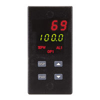
red lion TCU Instruction Manual (103 pages)
Brand:
red lion
| Category:
Temperature Controller
| Size: 1 MB
Table of Contents
Table of Contents
3
General Description
9
Safety Summary
10
Installation & Connections
11
Installation Environment
11
Standard Unit Installation
11
NEMA 4X/IP65 Unit Installation
11
Unit Removal Procedure
13
Removing Bezel Assembly
13
Installing Bezel Assembly
13
Output Modules
14
Output Module Restrictions
14
Installing Output Modules
14
Typical Connections
14
Select Input Sensor Type
15
Select AC Power (115/230 VAC)
15
Emc Installation Guidelines
16
Wiring Connections
16
Signal Wiring
17
Valve Positioner Wiring
18
Linear DC Output Wiring
18
Second Analog Input Wiring
18
Heater Current Monitor Wiring
19
Program Disable or User Input Wiring
19
AC Power Wiring
19
Front Panel Description
20
Button Functions
20
Operation Overview
21
Controller Power-Up
21
Controller Power down
21
Process Start-Up
21
Manual (User) & Automatic Operation
21
Remote and Local Setpoint Operation
22
Configuration of Parameters
23
Parameter Entry
24
Normal Display Mode
24
Modifying a Secondary Display Parameter from the Front Panel
24
Unprotected Parameter Mode
25
Unprotected Parameter Mode Reference Table
25
Protected Parameter Mode Reference Table
27
Protected Parameter Mode
27
Front Panel Program Disable
28
Models with User Input
28
Models with Program Disable
28
Hidden Function Mode
29
Hidden Function Mode Reference Table
29
Configuration Parameter Modules
30
Input Module (1- In)
30
Input Type (Type)
30
Temperature Scale (SCAL)
30
Temperature Resolution (Dcpt)
30
Input Signal Filter and Display Update Rate (Fltr)
30
Input Sensor Correction Constants (SPAN & Shft)
31
Setpoint Limit Values (SPLO & SPHI)
31
Setpoint Ramp Rate (Sprp)
31
User Input
32
Heater Current Monitor Scaling (Hcur) (Optional)
32
Output Module (2-OP)
33
Time Proportioning Cycle Time (Cyct)
33
Output Control Action (OPAC)
33
Output Power Limits (OPLO & OPHI)
33
Sensor Fail Preset Power (OPFL)
33
Output Power Dampening (Opdp)
34
ON/OFF Control Hysteresis Band (CHYS)
34
Auto-Tune Dampening Code (Tcod)
34
Linear DC Analog Output (ANAS, ANLO, ANHI, Andb, Anut) (Optional)
35
Phone: 800.894.0412 - Fax: 888.723.4773 - Web: Www.clrwtr.com - Email: Info@Clrwtr.com Lockouts Module (3-LC)
36
Lower Display Lockouts (SP, OP, Hcur, IN-2, Dev, Udsp)
36
Protected Mode Lockouts (Code, PID, PID2, Rtbs & AL)
36
Hidden Mode Lockouts (Alrs, Trnf, Tune and SPSL)
36
Alarm Module (4-AL) (Optional)
37
Alarm Action (Act1, Act2)
37
Second Analog Input Alarm
37
Heater Break Alarm (Hcur)
37
Valve Fail Alarm (VFAL)
37
Alarm Reset (Rst1, Rst2)
41
Alarm Standby Delay (Stb1, Stb2)
41
Alarm Value (AL-1, AL-2)
41
Alarm Hysteresis (AHYS)
42
Cooling Output Module (5-02) (Optional)
42
Cooling Cycle Time (CYC2)
42
Cooling Relative Gain (GAN2)
42
Heat-Cool Overlap/Deadband (Db-2)
42
Serial Communications Module (6-SC) (Optional)
43
Baud Rate (Baud)
43
Parity Bit (Parb)
43
Address Number (Addr)
43
Abbreviated or Full Transmission (Abrv)
43
Print Rate (Prat)
43
Print Options (Popt)
44
Second Analog Input Module (7-2N) (Optional)
44
Operation Mode (Oper)
44
Square Root Linearization (Root)
44
Decimal Point Position (Dpt2)
45
Second Analog Input Scaling Points (Dsp1, INP1, Dsp2, INP2)
45
Signal Input Values (INP1 & INP2)
45
Local/Remote Setpoint Transfer Modes (Sptr)
46
Secondary Output Power Dampening (Opd2)
46
Valve Positioner Module (8-VP)
46
Valve Position 1 and Valve Position 2 (VPS1, VPS2)
46
Valve Update Time (Vudt) (Position and Velocity Mode)
47
Valve Position Deadband (Vpdb) (Position Mode)
47
Valve Fail Time Alarm (VFAL) (Position Mode)
47
Valve Motor Open Time and Valve Motor Close Time (Vopt, Vclt) (Velocity Mode)
47
Valve Minimum on Time (Vont)(Velocity Mode)
47
Factory Service Operations Module (9-FS)
47
Reference Table: Configuration Parameter Module
48
Configure Module 1 - Input Parameters (1-IN)
48
Configure Module 2 - Output Parameters (2-OP)
49
Configure Module 3 - Lockout Parameters (3-LC)
50
Configure Module 4 - Alarms (4-AL)
51
Configure Module 5 - Cooling Parameters (5-O2)
52
Configure Module 6 - Serial Communications (6-SC)
53
Configure Module 7 - Second Analog Input (7-2N)
54
Configure Module 8 - Valve Positioner (8-VP)
54
Configure Module 9 - Factory Service Operations (9-FS)
55
Rs485 Serial Communications Interface
56
Communication Format
56
Sending Commands and Data
56
Output Status
57
Receiving Data
59
Terminal Emulation Program for IBM PC
61
Serial Connections
62
Terminal Descriptions
62
Connecting to a Host Terminal
64
Troubleshooting Serial Communications
64
Heater Current Monitor Option
65
Valve Position Option
66
Position Mode Valve Control
66
Velocity Mode Valve Control
67
Second Analog Input Option
68
Remote Setpoint
68
Temperature Ratio Control
68
Temperature Remote Setpoint Slave Control
68
Phone: 800.894.0412 - Fax: 888.723.4773 - Web: Www.clrwtr.com - Email: Info@Clrwtr.com Cascade Control
68
External Cascade Control
69
Internal Cascade Control
70
Pid Control
71
Proportional Band
71
Integral Time
71
Derivative Time
72
Output Power Offset (Manual Reset)
72
PID Adjustments
72
On/Off Control
74
Auto-Tune
76
Initiate Auto-Tune
77
Auto-Tune of Heat/Cool Systems
77
Auto-Tune of Internal Cascade Controllers
77
Auto-Tune of External Cascade Systems (Remote Setpoint)
78
APPENDIX“A”-Applicationexamples ··········································· 71
79
APPENDIX "A" - Application Examples
79
Plastics Extruder Application
79
Temperature Control Programming Example
80
Appendix "B" - Specifications and Dimensions
81
Appendix "C" - Troubleshooting
86
Appendix“C”-Troubleshooting ············································ 78
88
Appendix “B” - Specifications and Dimensions ·······························73
88
Output Leakage Current
88
Appendix“D”-Manualtuning ··············································· 81
89
Appendix "D" - Manual Tuning
89
Open Loop Step Response Method
89
Closed Loop Cycling Method
90
Appendix“E”-Calibration·················································· 83
91
Appendix "E" - Calibration
91
Calibration Check
91
MV Reading Check
91
Thermocouple Cold Junction Temperature Check
91
RTD Ohms Reading
91
Linear DC Output Check
91
Second Input Check
92
Heater Current Monitor Check
92
Second Analog Input Check
92
Valve Positioner Check
92
Calibration
92
Configure Step 9 - Factory Service Operations (9-Fs)
92
Millivolt Calibration (Cal)
93
Thermocouple Cold Junction Calibration (CJC)
93
RTD Ohms Calibration (Rtd)
93
Analog Output Calibration (ANCL)
93
Second Analog Input Calibration (2CAL)
94
Second Analog Input (Remote Setpoint)
94
Heater Current Monitor
94
Motorized Valve Positioner
94
Appendix "F"- User Parameter Value Chart
95
Appendix "G" Ordering Information
98
Limited Warranty
103
Advertisement
red lion TCU Product Manual (11 pages)
Temperature Control Unit
Brand:
red lion
| Category:
Temperature Controller
| Size: 1 MB
Table of Contents
Safety Summary
2
Specifications
2
Serial Communication
3
Environmental Conditions
3
Controller Programming
6
Hidden Function Mode
7
Output Modules
8
Typical Connections
8
Ordering Information
9
Limited Warranty
10
Advertisement
Related Products
red lion TCU10000
red lion T16
red lion T4811000
red lion T4811104
red lion T4820000
red lion T4821100
red lion T4821104
red lion T481011A
red lion T4810115
red lion T4811102
red lion Categories
Measuring Instruments
Water Pump
Controller
Cash Counter
Switch
More red lion Manuals
Login
Sign In
OR
Sign in with Facebook
Sign in with Google
Upload manual
Upload from disk
Upload from URL