Table of Contents
Advertisement
Advertisement
Table of Contents

Related Manuals for ELNA easy cover


Summary of Contents for ELNA easy cover
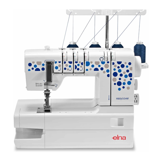
- Page 1 SERVICE MANUAL MODEL: easy cover...
-
Page 2: Table Of Contents
Table of Contents Replacing the External Parts 1. Belt Cover ..................1 2. Looper Cover ................... 2 3. Rear Cover ..................3 4. Front Cover ..................4 5. Free Arm Cover ................5 Mechanical Adjustment 1. Presser Bar Height ................6 2. -
Page 3: Replacing The External Parts
Replacing the External Parts 1. Belt Cover To remove: z Remove the setscrews q and remove the belt cover w. To attach: x Follow the above procedures in reverse. -
Page 4: Looper Cover
2. Looper Cover To remove: z Remove the setscrews q and remove the looper cover w (with a hinge attached). To attach: x Follow the above procedures in reverse. -
Page 5: Rear Cover
3. Rear Cover To remove: z Raise the handle q and remove the setscrews w, e and r. Remove the rear cover t. To attach: x Follow the above procedures in reverse. -
Page 6: Front Cover
4. Front Cover To remove: z Remove the face plate, belt cover, looper cover and rear cover. x Remove the setscrews q, w, e and r. Remove the front cover t. To attach: c Follow the above procedures in reverse. -
Page 7: Free Arm Cover
5. Free Arm Cover To remove: z Remove the setscrews q and the free arm cover w. To attach: x Follow the above procedures in reverse. -
Page 8: Mechanical Adjustment
Mechanical Adjustment 1. Presser Bar Height The distance between the bottom of the presser foot in up position and the needle plate should be 4.7–5.3 mm. z Remove the face plate and front cover. x Remove the setscrews q, and lamp set plate w. c Raise the presser foot and loosen the setscrew e. -
Page 9: Foot Pressure
2. Foot Pressure The pressure adjusting screw should protrude 10 mm from the top of the machine. 10 mm z Turn the adjusting screw q to set its height at 10 mm. -
Page 10: Needle Bar Height
3. Needle Bar Height The distance between the point of the left needle (Schmetz ELx705, size 80/12) and the upper surface of the needle plate should be 7.8–8.2 mm when the needle bar is at the highest position. z Remove the face plate and front cover. x Remove the setscrews q and lamp set plate w. -
Page 11: Feed Dog Height
4. Feed Dog Height Turn the handwheel toward you to raise the feed dog to its highest position. When the presser foot is lowered, the maximum height of the feed dog should be 0.75-0.95 mm above the needle plate. 0.75-0.95 mm z Set the stitch length dial at 3 and differential feed dial at 1.0. -
Page 12: Looper Height
5. Looper Height The height of the looper point should be 72.6–73.0 mm. z Remove the free arm cover and needle plate. x Replace the right needle with the short test pin (28.8 mm long) q. c Turn the handwheel toward you to bring the looper w to its rightmost position. -
Page 13: Looper Postion
6. Looper Position The distance between the looper point and center of the right needle should be 1.8–2.2 mm when the looper is at its rightmost position. z Remove the free arm cover and needle plate. x Replace the right needle with the short test pin (28.8 mm long) q. -
Page 14: Needle To Looper Timing
7. Needle to Looper Timing When the point of the looper meets with the right side of the needle on the right, the needle bar rises 1.3-1.5 mm from the lowest position. z Remove the free arm cover and needle plate. x Replace the right needle with the long test pin (30.24 mm long) q. -
Page 15: Clearance Between The Needle And Looper
8. Clearance between the Needle and Looper The clearance between the looper point and scarf of the needle (Schmetz ELx705, size 80/12) should be 0–0.05 mm 0–0.05 mm. z Remove the free arm cover and needle plate. x Turn the handwheel toward you until the looper point q comes behind the needle. -
Page 16: Back Needle Guard Height
9. Back Needle Guard Height The upper edge of the back needle guard should be 2.6–3.0 mm below the lower edge of the looper point when the looper point meets with the right side of the needle. z Remove the free arm cover and needle plate. x Turn the handwheel toward you until the looper point q matches with the right side of the needle. -
Page 17: Needle To Feed Dogs Timing
10. Needle to Feed Dogs Timing The point of the left needle should be 2.9–3.1 mm above the upper surface of the needle plate when the top of the feed dogs are level with the upper surface of the needle plate in downward motion. -
Page 18: Stitch Length
11. Stitch Length The stitch length should be 30–32 mm when the stitch length dial is set at 3 and differential feed dial at 1.0. z Remove the belt cover. x Set the stitch length dial q at 3 and differential feed dial w at 1.0. -
Page 19: Differential Feed Ratio
12. Differential Feed Ratio The main and sub feed dogs should move uniformly together when the stitch length dial is set at 3 and differential feed dial at 1.0. z Remove the belt cover. x Set the stitch length dial at 3 and differential feed dial at 1.0. -
Page 20: Thread Tension
13. Thread Tension The standard thread tension measured with the King brand white polyester thread (#50) should be as follows: q Left needle thread: 65–75 grams (Dial set at 4) w Center needle thread: 55–65 grams (Dial set at 4) e Right needle thread: 45–55 grams (Dial set at 4) r Looper thread: 9–15 grams (Dial set at 3) z Remove the front cover. -
Page 21: Motor
14. Motor To replace: z Remove the belt cover and rear cover. x Remove the setscrews q and machine socket w. c Disconnect the motor cords e, r, t and y from the connector tabs A, B, C and D. v Remove the setscrews u and remove the motor.