Table of Contents
Advertisement
Quick Links
Instruction Manual
for the
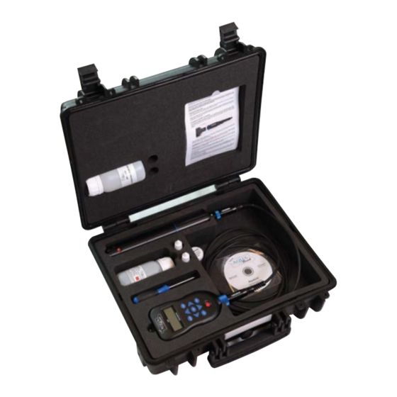
Aquaprobe
AP-700, AP-800 & AP-2000
®
Multiparameter Water Quality Probe
and associated
Aquameter
®
, Utilities & Accessories
Aquaprobe
®
firmware Revision 4.07 and Above
Aquameter
®
firmware Revision 6.20 and Above
Document No. 10401-00870
Revision: R
Date: March 27, 2017
Aquaread
Ltd
®
Bridge House
Northdown Industrial Park
Broadstairs
Kent
CT10 3JP
ENGLAND
Phone: +44 1843 600 030
www.aquaread.com
Advertisement
Table of Contents
Troubleshooting


Need help?
Do you have a question about the Aquaprobe AP-800 and is the answer not in the manual?
Questions and answers