Table of Contents
Advertisement
Advertisement
Table of Contents

Subscribe to Our Youtube Channel
Related Manuals for Airspan Air4G


Summary of Contents for Airspan Air4G
- Page 1 UGD-D00229 Rev B Air4G Installation Guide...
-
Page 2: Copyright
Information supplied by Airspan Networks Inc. is believed to be accurate and reliable. However, no responsibility is assumed by Airspan Networks Inc. for the use thereof nor for the rights of third parties which may be effected in any way by the use of thereof. -
Page 3: Table Of Contents
Federal Communication Commission Notice ................13 GPS Compliance ........................13 Maximum Output TX Power ......................14 Power Consumption ........................15 Antenna Types..........................15 Air4G Antenna Usage ......................16 About this Guide ........................18 Purpose .......................... 18 Intended Audience ......................18 Conventions ........................18 Referenced Documentation .................... - Page 4 Install Dual Slant Antenna ..................44 5.5.2 Install Quad Slant Antenna ..................45 5.5.3 Install Omni Antenna ....................48 Optional Mounting Antenna on Air4G ................48 5.6.1 Variable Tilt Antenna ....................49 Cavity Filter Installation....................50 External Duplexer Installation ..................50 5.8.1...
- Page 5 Air4G Installation Guide Securing Fiber-optic Cable ..................... 66 Connecting the Fiber-optic Cable ................... 68 Appendix C – Glossary of Terms ..................70 Appendix D – Installation Checklist ..................72 Appendix E ......................... 73 12.1 Revision History ......................73 12.2 Contact Information ......................73...
-
Page 6: Summary Of Figures
Figure 3 - Air4G – each sector connected separately ..............22 Figure 4 – Workflow of Installation ....................23 Figure 5 - PS – Air4GTable 13 - Air4G wall mount installation parts ..........29 Figure 6 – Air4G Base Station Unit, Ethernet termination .............. 33 Figure 7 –... - Page 7 Figure 50 - Junction box with mounting brackets assembled ............57 Figure 51 - mounting bracket (2 required) ..................57 Figure 52 - Air4G assembly with optional junction box ..............59 Figure 53 – Ethernet connector cable termination ................. 60 Figure 54 –...
-
Page 8: Summary Of Tables
Table 11 - GPS Kit Contents ......................27 Table 12 - Input Power for Air4G ....................28 Figure 5 - PS – Air4GTable 13 - Air4G wall mount installation parts ..........29 Table 14 - Air4G pole mount installation parts ................30 Table 15 - Air4G additional parts and kits .................. -
Page 9: Warnings And Cautions
Warnings and Cautions Human Exposure to Radio Frequencies The Air4G antennas should be installed and operated from a minimum distance of 2.4 meters (for 5.x, 3.x, 0707, 0808 and 1.x) or 3.4 meters (for 2.x) from your body. Radio Interference This Air4G generates, uses, and can radiate radio frequency energy and, if not installed and used in accordance with the instructions, may cause harmful interference to radio communications. -
Page 10: Warning Symbols
It is the user’s responsibility to install this device in accordance with the local electrical codes. 11. Installation of the Air4G must be contracted to a professional installer. 12. Disconnect Device. The socket outlet should be easily accessible in case you have to disconnect the device. - Page 11 Air4G Installation Guide national codes for electrical grounding and safety. Failure to meet safety requirements and/or use of non-standard practices and procedures could result in personal injury and damage to equipment. A direct lightning strike may cause serious damage even if these guidelines are followed.
-
Page 12: Declaration Of Conformity
Direktiv 1999/5/EC. Român: Acest echipament este în conformitate cu cerinţele esenţiale şi alte prevederi relevante ale Directivei 1999/5/CE. The Declaration of Conformity related to this product can be obtained from PLM@Airspan.com. Page 12 Commercial in Confidence UGD-D00229 Rev B... -
Page 13: Fcc Notice
Air4G Installation Guide FCC Notice Federal Communication Commission Notice This equipment has been tested and found to comply with the limits for a Class A digital device, pursuant to part 15 of the FCC Rules. These limits are designed to provide reasonable protection against harmful interference when the equipment is operated in a commercial environment. -
Page 14: Maximum Output Tx Power
Air4G Installation Guide Maximum Output TX Power Table 1 - Air4G FCC Maximum Output TX Power Frequency Band Antenna Gain EIRP 700 MHz 41.6 dBm 55.1 dBm 13.5 dBi 800 MHz pending pending pending 1.8 GHz pending pending pending 2.3 GHz 40.26dBm... -
Page 15: Power Consumption
Air4G Installation Guide Power Consumption Table 3 - Power Consumption Frequency WiMAX LTE Operation Range Operation (Nominal) (Nominal) 150W 184W 137W 171W 200W 236W 173W 207W 700/800M 129W 163W Antenna Types Table 4 - 700 MHz Antenna Types -Technical Type... -
Page 16: Air4G Antenna Usage
Manual Electric Tilt (MET) dual/quad antennas - a variable tilt antenna available for mounting directly on the Air4G with no need for physical tilting of the antenna. The following table describes different antenna arrays when using either two (2) receivers or four... - Page 17 Air4G Installation Guide 2.3-2.7 GHz 60º Quad X-Polar 2.3 GHz 65º 2.5 GHz 65º 2.3-2.7 GHz 60º Dual Slant X- Polar Antenna 2.5 GHz 65º 2.3-2.7 GHz 60º Quad X-Polar 3.3-3.8 GHz 65º 3.3-3.8 GHz 60º Dual Slant X- Polar 3.3-3.8 GHz...
-
Page 18: About This Guide
Connect and Manage Cables Set Power System 1.2 Intended Audience This guide is intended for persons who are responsible for Installing the Air4G. These persons should have a working knowledge of the WiMAX system. 1.3 Conventions This document uses the following informational conventions. - Page 19 Air4G Installation Guide Set Power System Appendixes [Review Job Sheet, Securing & Connecting the Fiber-Optic cable, Glossary of Terms, Installation Checklist, Contact information and Revision history] Page 19 Commercial in Confidence UGD-D00229 Rev B...
-
Page 20: Introduction
37dBm (5W) transmitters in 3.x GHz and dual 35dBm (2W) in the 5.x GHz band. Air4G is an outdoor radio that is mounted outside on a pole or wall. Air4G is available in numerous frequency bands and in numerous channels. For more details please consult the Air4G Product Spec. -
Page 21: Figure 1 – Air4G – Daisy Chain Configuration
Air4G Installation Guide Figure 1 – Air4G – Daisy Chain configuration Figure 2 – Air4G – Star configuration An alternative architecture, where each sector is connected separately to the backhaul/backbone solution, therefore avoiding a single point of failure, as shown below:... -
Page 22: Figure 3 - Air4G – Each Sector Connected Separately
(Eth 1) is disabled. Note: Auto-negotiation must always be enabled on the core network side. Note: The Ethernet connection (Eth 2) can be enabled / disabled via the Air4G WEB interface to prevent unauthorized use. Check to enable, uncheck to disable. -
Page 23: Getting Started
Caution: Antennas 1 & 2 Tx/Rx must be connected and attached before Air4G is powered on. 3.2 Air4G Installation Checklist Plan the installation of the Air4G by using the Installation Checklist, which you can find as a removable job aid in Appendix A for this guide. -
Page 24: Verify Prerequisites
Air4G Installation Guide Verify Prerequisites Prior to installing the Air4G, verify the required safety, power, tools, parts and components. Reference: Set up requirements for the installation is detailed in the Job Sheet, Appendix A for this guide. 4.1 Verify Safety Requirements Read and follow all warning notices and instructions marked on the product or included in this manual. -
Page 25: Verify Installation Requirements
12AWG x 6 (ordered separately) – up to 100 meters 1 x Ethernet LTW IP68 or Amphenol environmental connector RJ45 environmental shroud Sunshield with Air4G-W24-Sunshield – Sunshield kit including quad antenna adaptor brackets Antenna (x 2) – including fixing accessories. Adaptor (optional) (ordered separately) - Page 26 1 x Air4G Wall Air4G-W24-WMK-3 – wall mounting kit with accessories included mounting kit Pole (& Wall) Air4G-W24-PMK-60-120-1 – Pole (with Wall) mounting kit for poles with Mounting Kit for diameters 60-120 mm – including fixing accessories. pole with 60-...
-
Page 27: Table 11 - Gps Kit Contents
Supplied with Air4G antenna ports and the Duplexer Air4G RF cable 2 x antenna cables for connecting the antennas to the Air4G / External (ordered Duplexer. separately) The following table displays the parts contained in the included GPS Kit and when the parts are required per configuration. -
Page 28: Table 12 - Input Power For Air4G
Note: For additional cable lengths contact your Airspan representative. The Air4G power supply (PS) can be installed with various cable lengths according to the site requirements. The cable lengths are determined by the length of the run between the PS and the Air4G. - Page 29 Air4G Installation Guide Figure 5 - PS – Air4G Page 29 Commercial in Confidence UGD-D00229 Rev B...
-
Page 30: Table 14 - Air4G Pole Mount Installation Parts
Air4G Installation Guide Table 13 - Air4G wall mount installation parts Parts Images Wall Plate Top Hanger Lower Hanger GPS Antenna mounting bracket w/Handle (pre- assembled) Handle (pre-assembled) Table 14 - Air4G pole mount installation parts Parts Images Note: in addition to the Wall mounting kit. -
Page 31: Table 15 - Air4G Additional Parts And Kits
Air4G Installation Guide Table 15 - Air4G additional parts and kits Additional Common Accessories (not provided by Airspan) Spare RJ45 connectors Cable ties Ring terminal for earth strap. M5 / M6 Earth strap cable (4-6 mm) (yellow and green cable) Weatherproof / Outdoor mains cable splice kit or termination box. -
Page 32: Verify Components
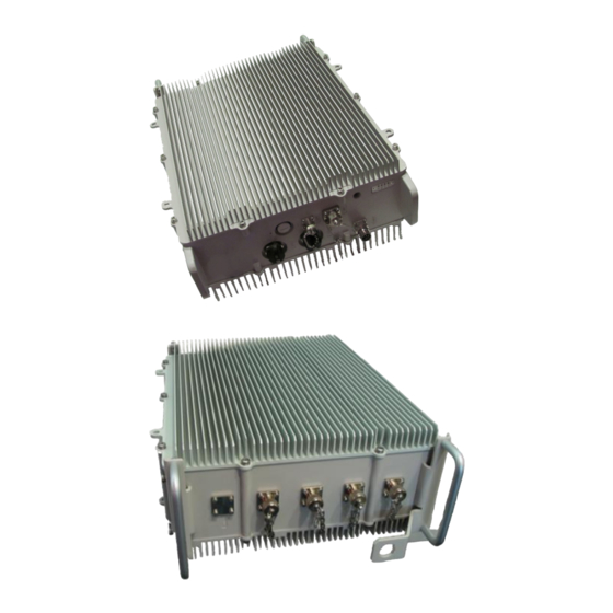
(for some FDD variants only) + RF cables. 2 x pole bands (stainless steel) (for 50-215 mm pole) 4.2.3 Verify Components Air4G is shown below from the Ethernet termination and RF port end views respectively. Page 32 Commercial in Confidence UGD-D00229 Rev B... -
Page 33: Figure 6 – Air4G Base Station Unit, Ethernet Termination
Air4G Installation Guide Figure 6 – Air4G Base Station Unit, Ethernet termination Figure 7 – Air4G Base Station Unit, RF ports 4.2.3.1 Physical Dimensions Air4G BS is in an all outdoor enclosure. Table 19 - Air4G 3.x physical dimensions Parameter Value... -
Page 34: Figure 8 - Junction Box With Pole Assembly
Depth 170 mm (6.69 inches) Weight 17.6 kg (38.80 lbs.) RF Ports for antenna connections are N-Type Female connectors located on the top of the Air4G enclosure. 4.2.3.2 Junction Box (Optional) The Junction box (optional) is an outdoor enclosure that measures 160 mm (6.3 in.), 160 mm (6.3 in.) and 75 mm (2.95 in.). -
Page 35: Figure 10 - External Duplexer Bottom Panel
Air4G Installation Guide Figure 10 - External Duplexer bottom panel Figure 11 - External Duplexer top panel Table 21 - External Duplexer variants Variant Band Weight Air4G-L22-0707LF (700MM2) 12, 17 9.2 Kg (20.28 Lbs.) Air4G-L22-0806LF (800MM2) 7 Kg (15.43 Lbs.) -
Page 36: Install Air4G
Air4G Installation Guide Install Air4G Install the Air4G base station by pole mount, wall mount, or single point. The Air4G can be connected to various types of antennas via standard RF coaxial cables. Antennas are positioned with up to 10 wavelengths horizontal separation to give optimal Downlink and Uplink MIMO performance. -
Page 37: Figure 14 - Pole Bracket Wrap
Figure 14 - pole bracket wrap 2. Align and position each of the 2 pole clamp brackets at the heights required to attach the Air4G (with the threaded holes facing up). Adjust the upper bracket and tighten in place. Adjust the lower bracket and hand-tighten. -
Page 38: Wall Mount Configuration
1. Attach the two (2) pole brackets (as shown in Table 14) to the pole (with the threaded holes facing up) at the heights required to attach the Air4G. This comes as a set of two (2), upper and lower pairs. -
Page 39: Figure 20 – Wall Mounted Air4G Wall Plate Details
To mount the Air4G in the wall mount configuration, perform the following steps: 1. Attach the Wall Plate to the wall at the height required to attach the Air4G. 2. Fasten the Hangars to the rear side of the Air4G enclosure, position the niched Hangar so it is lower on the wall with the niche facing down. -
Page 40: Mounting Examples
Air4G Installation Guide 4. Screw the bottom two screws and washers into the two standoff fittings at the bottom of the Air4G enclosure. 5. Tighten all fixing screws. 5.2.1 Mounting Examples The following displays a typical wall mount. Figure 21 - Wall mount Note: The GPS bracket (pre-assembled) is on the (back) side closest to the wall so as not to interfere with the sunshield assembly. -
Page 41: Lightning /Surge Protector Installation
Surge protector to the Base Station. A 80cm, cable - RG58 TNC-TNC (P/N CBL-GPS-TNC-0.8-1) for mounting the GPS directly to the top of Air4G. This should be used in conjunction with the BS GPS antenna mounting bracket pre- assembled on the BS. -
Page 42: Figure 25 - Surge Protector Installation
(RG58 TNC-TNC) extends from the Surge Protector to the GPS antenna mounted on top of the BS. If the GPS antenna is assembled in an alternate location (not on top of the Air4G), the 80cm cable can be substituted with the 16m or 40m optional cable. -
Page 43: Air4G Connections
Figure 27 - Air4G connections (bottom) Note: Previous versions had 3 RJ45 (Ethernet) connections. 5.5 Install Air4G Antennas Use this procedure to install a linear dual slant antenna for the Air4G in the mast mount configuration. Page 43 Commercial in Confidence... -
Page 44: Install Dual Slant Antenna
5.5.1 Install Dual Slant Antenna Figure 29 - Air4G Antenna Dual Slant Mast Mount Configuration Note: Mounting kit (50 > 115 mm) is included. To mount the dual slant antenna for the Air4G in the mast mount configuration, perform the following steps: Page 44... -
Page 45: Install Quad Slant Antenna
Figure 30 – Air4G Antenna Quad Slant Mast Mount Configuration Note: Mounting kit (50 > 115 mm) is included. To mount the Quad slant antenna for the Air4G in the mast mount configuration, perform the following steps: 1. Attach the Antenna brackets to the top and bottom of the radome. -
Page 46: Figure 31 - Adjustable Mounting Kit, With Snaplock Stainless Steel Bands
6. Tighten all fixing screws. 7. Attach, connect and secure antenna RF cable between the antenna and the appropriate Air4G Antenna RF connection on the top of the unit. 5.5.2.1 Antenna Mounting Clamps for Dual and Quad Slant Antennas The following are some adjustable antenna mounting clamp options for both Dual and Quad Slant antenna scenarios. -
Page 47: Figure 32 - Adjustable Mounting Kit, With 'V' Blocks
Air4G Installation Guide Figure 32 - Adjustable Mounting Kit, with ‘V’ Blocks Page 47 Commercial in Confidence UGD-D00229 Rev B... -
Page 48: Install Omni Antenna
This describes the mounting of the Omni mast mount antenna (ordered separately). Figure 34 - possible Omni antenna array To mount the Omni antenna for the Air4G in a mast mount configuration, perform the following steps: 1. Assemble Omni antenna array on the ground at the installation site. -
Page 49: Variable Tilt Antenna
Air4G Installation Guide 5.6.1 Variable Tilt Antenna There is a Variable Tilt Antenna available for mounting on the Air4G. The antenna maybe connected directly to the Air4G with no need for physical tilting of the antenna.The Manual Electric Tilt (MET) antenna has a rotating nut that adjusts a threaded rod which moves in and out while displaying a tilt scale, as shown below. -
Page 50: Cavity Filter Installation
Air4G Installation Guide 5.7 Cavity Filter Installation The following demonstrates the correct installation of a Cavity filter for the Air4G in either the wall or mast mount configuration. Note: The Cavity filters are required for the 2.3 GHz variant only. -
Page 51: Figure 38 - Pole Mounting Stainless Steel Bands (2 Required)
Air4G Installation Guide 1. Position the external Duplexer above the area where the Air4G will be attached. Verify that the distance between the external Duplexer is well within the length of the provided RF jumper cables, i.e. 1.5 meters or less. -
Page 52: External Duplexer To Air4G Connection
“+45 degree” ports and two “-45 degree” ports. To provide maximum efficiency one Air4G Tx/Rx port must be connected to a “+45 degree” port in the quad port antenna and another Air4G Tx/Rx port must be connected to a “-45 degree” port in Page 52... -
Page 53: Gps Antenna Assembly
Air4G Installation Guide the quad port antenna. The Air4G Rx ports need to be connected to the remaining connectors on the antenna side. Two (2) examples are displayed below. Table 24 - Antenna connection Air4G port Port Label on Air4G... -
Page 54: Gps Antenna Mounting
Cables should have some slack for thermal expansion/contraction between fastenings. An 80cm, cable connects the GPS directly to the top of Air4G. When mounting the GPS antenna remotely from the base station unit, the GPS antenna should be used in conjunction with the Remote GPS Antenna Mounting Bracket (GPS-MNT-1) and either the 16m (CBL-GPS-TNC-16-1) or the 40m (CBL-GPS-TNC-40-1) GPS Cable RG58 TNC-TNC by way of TNC connectors. -
Page 55: Remote Mounting Of Gps Antenna
Figure 46 - GPS antenna assembled on bracket 10. Connect the RG58 cable attached to the GPS Lightning/Surge protector (required) to the GPS connection on the bottom Air4G. Note: Affix the cable to the BS to avoid strain on the connections. -
Page 56: Led Display
When interference is present the GPS antenna can be installed in a position lower than the base station using the 40m (CBL-GPS-TNC-40-1) shielded GPS Cable. An example displaying the mounting of the GPS antenna on the tower below the Air4G is displayed below: Figure 49 - GPS Remote mounting Note: All cables should be properly secured to prevent undue strain on any of the cable terminations. -
Page 57: Install Junction Box (Optional)
Air4G Installation Guide 5.12 Install Junction Box (Optional) Note: Contact Airspan customer-service to determine whether junction box installation is required. Installation may be required, depending on the distance between the external power-supply and the BS, as well as the minimum voltage supplied by the power-supply. -
Page 58: Table 26 - Cable Hole Sizes
10. Open the connector clamp collar and feed about 101.6 mm (4 inches) of cable from the Air4G through it and into the box. Tighten the collar around the cable, forcing the seal to compress around the cable. 11. Replace the cover by using the four (4) screws, ensuring the gasket (for weatherproofing) is firmly in place on the rim of the cover. -
Page 59: Figure 52 - Air4G Assembly With Optional Junction Box
Air4G Installation Guide Figure 52 - Air4G assembly with optional junction box Page 59 Commercial in Confidence UGD-D00229 Rev B... -
Page 60: Connect And Manage Cables
Air4G Installation Guide Connect and Manage Cables The Ethernet cable is connected to the Air4G using a standard RJ45 connector protected by a harsh environment protective casing. Figure 53 – Ethernet connector cable termination 6.1 Assemble Ethernet Connector 1. Pass the Cat 5 cable through the seal, front connector, body and tail nut of the environmental connector casing as shown above. -
Page 61: Set Power System
Each unit is provided with a 3/10/30 meter 48 volt power cable terminated with a female connector at one end to be connected to the Power connector on the bottom panel of the Air4G and bare wires at the other. -
Page 62: Initial Web Configuration
Air4G Installation Guide Initial WEB Configuration Configure an Air4G base station using the built in web based interface. This prepares the equipment for connection to Netspan. 8.1 Initial configuration To set initial configuration, perform the following: Caution: The GPS antenna should be installed and attached before Air4G is powered on. -
Page 63: Snmp Agent/Trap Configuration
Air4G Installation Guide 6. Enter the BS ID Note: The format of the BS ID is important: NN-NN-NN-nn-nn-nn (where NN- NN-NN is the Operator ID and nn-nn-nn is a unique address ID). 7. Select the BS Action from the available list. -
Page 64: Bs Operational State
Air4G Installation Guide Figure 59 - Management IP Configuration 2. Define the IP address. 3. Define the Subnet Mask. 4. Define the Default GW MAC Address. Caution: Define Default GW only if required for Network Security. Consult with Provider. 1. Set the Management VLAN set to Untagged. Set to Tagged when with VLAN Tag ID. -
Page 65: Figure 60 - Operational State
Air4G Installation Guide Figure 60 - Operational State Page 65 Commercial in Confidence UGD-D00229 Rev B... -
Page 66: Review Job Sheet
Air4G Installation Guide Appendix A 9.1 Review Job Sheet The Job Sheet should include the following information: BS location and identity. Whether the system is required to be locked to a GPS timing reference. A BSID is required for each BS. This should be in a format xxxxxx:xxxxxx where x is a decimal digit. -
Page 67: Figure 61 - Secure Fiber-Optic Cable, Place Tie
Air4G Installation Guide Figure 61 - Secure fiber-optic cable, place tie 2. Pull or slide the Millie-Tie onto the target. Note that the Millie Tie stretches to cushion the installation. Figure 62 – Secure fiber-optic cable, pull tie 3. Release the tension when snug, then cut and remove any excess strip. Always cut through the square sections, not the wider cells. -
Page 68: Connecting The Fiber-Optic Cable
Figure 66 – Secure fiber-optic cable, re-use excess tie 9.3 Connecting the Fiber-optic Cable To secure fiber-optic cable to the Air4G, perform the following steps: 1. Remove the dust cover from end of a panel connector: Figure 67 - fiber-optic connector with dust cover Figure 68 –... -
Page 69: Figure 69 - Fiber-Optic Outdoor Connector Plug (Multimode)
Air4G Installation Guide Figure 69 - Fiber-Optic Outdoor Connector Plug (multimode) Figure 70 - screw hand-tight Figure 71 - Fiber-optic cable connected Page 69 Commercial in Confidence UGD-D00229 Rev B... -
Page 70: Appendix C - Glossary Of Terms
Air4G Installation Guide 10 Appendix C – Glossary of Terms Authentication, Authorization and Accounting Advanced Antenna System Application Function Automatic Repeat reQuest Access Service Network ASN GW ASN Gateway ATCA Advanced Telecommunications Computing Architecture Base Station Broadband Wireless Access CHAP... - Page 71 Air4G Installation Guide OBSAI Open Base Station Standard Initiative OFDMA Orthogonal Frequency Division Multiplexing (Multiple Access) Paging Agent PAAA Proxy AAA Paging Controller Policy Function PHYsical Layer PMIP Proxy MIP Point-to-Point Protocol RADIUS Remote Authentication Dial In User Service Radio Resource Agent...
-
Page 72: Appendix D - Installation Checklist
Air4G Installation Guide 11 Appendix D – Installation Checklist The Checklist below gives the high-level steps in the Workflow for this procedure. Detach or print this page to use as a job-aid for completing the actions this procedure requires. Table 27 - Checklist for Procedure... -
Page 73: Revision History
Airspan Networks have introduced the Airspan Tracker application to enable prompt and efficient Customer Support services. If you do not have an Airspan Tracker account, please obtain login credentials by filling-in the form in the main page www.airspan.com/Support Register New Account Worldwide Headquarters: Airspan Networks Inc.
Need help?
Do you have a question about the Air4G and is the answer not in the manual?
Questions and answers