Advertisement
Quick Links
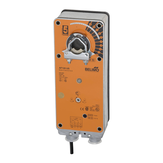
AF120 (-S) US, AF230 (-S) US
On-off, Spring Return Fail-Safe, 120 or 230 VAC
LISTED
U L
94D5
TEMP. IND &
.
REG. EQUIP
Technical Data
AF120 (-S) US
Power supply
120 VAC ± 10%
50/60 Hz
Power consumption
running: 6 W
holding: 2.3 W
Transformer sizing
10 VA
Electrical connection
3 ft, 18 GA appliance cable
1/2" conduit connector
Electrical protection
actuators are double insulated
Overload protection
electronic throughout 0° to 95° rotation
Angle of rotation
95°, adjustable 35 to 95° w/ ZDB-AF2
Torque
133 in-lb [15 Nm] constant
Direction of rotation
reversible with CW/CCW mounting
Position indication
visual indicator, 0° to 95° (0° is
spring return position)
Manual override
3mm hex crank (shipped w/actuator)
Auxiliary switches
2 x SPDT 7A (2.5A) @ 250 VAC, UL listed
(AF120/230-S)
one set at +5°, one adjustable 25° to 85°
Running time
150 sec. constant, independent of
load, spring return < 20 sec
Humidity
5 to 95% RH non-condensing
Ambient temperature
-22°F to +122°F [-30°C to +50°C]
Storage temperature
-40°F to +176°F [-40°C to +80°C]
Housing
NEMA type 2 / IP54
Housing material
zinc coated steel
Agency listings
UL 873 listed, CSA C22.2 No. 24 certified
Noise level
max. 45 dB (A)
Servicing
maintenance free
Quality standard
ISO 9001
Weight
6.9 lbs (3.1 kg)
22
Torque min. 133 in-lb, for control of air dampers
Application
For on-off, fail-safe control of dampers in HVAC systems.
Actuator sizing should be done in accordance with the damper
manufacturer's specifications. Control is on-off from an auxil-
iary contact, or a manual switch.
The actuator is mounted directly to a damper shaft up to 1.05"
in diameter by means of its universal clamp. A crankarm and
several mounting brackets are available for applications where
the actuator cannot be direct coupled to the damper shaft.
©
Operation
The AF series actuators provide true spring return operation for
reliable fail-safe application and positive close off on air tight
dampers. The spring return system provides consistent torque
to the damper with, and without, power applied to the actuator.
The AF series provide 95° of rotation and are provided with a
graduated position indicator showing 0° to 95°. The AF has a
unique manual positioning mechanism which allows the set-
AF230 (-S) US
ting of any damper position within its 95° of rotation. The AF
230 VAC ±14%
series actuators are shipped at +5° (5° from full fail-safe) to
provide automatic compression against damper gaskets for
50/60 Hz
tight shut-off. When power is applied to the AF series, the
6.5 W
manual mechanism is released. The actuators will now try to
2.5 W
close against the 0° position during its normal control opera-
tions. The manual override can also be released physically by
11 VA
the use of a crank supplied with the actuator.
The AF uses a brushless DC motor which is controlled by an
Application Specific Integrated Circuit (ASIC). The ASIC monitors
and controls the actuator's rotation and provides a digital rotation
sensing function to prevent damage to the actuator in a stall con-
dition. The actuator may be stalled anywhere in its normal rota-
tion without the need of mechanical end switches. The actuators
are Double Insulated so a ground connection is not required.
The AF120/230-S
iary switches. These SPDT switches are provided for safety
interfacing or signaling, for example, for fan start-up. The
switching function at the fail-safe position is fixed at +5°, the
other switch function is adjustable between +25° to +85°.
Dimensions
K4-2 US (supplied)
1/2" Centered
(Default)
3/4" Centered
(Field Selectable)
1.05" Centered
(Field Selectable)
K4-1 US (optional)
3/4" to 1.05"
Adjustable
K4 US (optional)
3/8" to 3/4"
Adjustable
version is provided with 2 built-in auxil-
US
[All numbers in brackets are in millimeters.]
0.65" [16.5]
0.19" [5]
10.47" [266]
0.39" [10]
2.64"
5.85" [148.5]
[67]
0.35" [9]
0.26" [6.5]
1.97"
[50]
®
Advertisement

Related Manuals for Belimo AF120 US


Summary of Contents for Belimo AF120 US
- Page 1 AF120 (-S) US, AF230 (-S) US ® On-off, Spring Return Fail-Safe, 120 or 230 VAC Torque min. 133 in-lb, for control of air dampers Application For on-off, fail-safe control of dampers in HVAC systems. Actuator sizing should be done in accordance with the damper manufacturer’s specifications.
- Page 2 Meets UL and CSA requirements without the need of an Meets UL and CSA requirements without the need of an electrical ground connection. electrical ground connection. On-off wiring for AF120 US and AF230 US On-off wiring for AF120-S US and AF230-S US...
-
Page 3: Installation Instructions
® Installation Instructions Quick-Mount Visual Instructions for Mechanical Installation Dimensions (All numbers in brackets are in millimeters.) IND-AF2 Position Indicator (optional) IND-AF2 Position Indicator (optional) Remove for 3/4” to 1.05” shafts QUICK-MOUNT VISUAL INSTRUCTIONS 3. Slide the actuator onto the shaft and tighten the nuts on the V-bolt with a 10mm wrench to 6-8 ft-lb of torque. - Page 4 For new construction work, order dampers with extended shafts. Instruct the installing contractor to allow space for mounting and service of the Belimo actuator on the shaft. The damper shaft must extend at least 3 1/2" from the duct. If the shaft extends less than 3-1/2"...
- Page 5 Installation Instructions ® Mechanical Installation adequate shaft length, slide the actuator over the shaft 4. Lock the clamp to the actuator using the retaining clip. with the side marked “CCW” (or the “CW” side if this is the 5. Verify that the damper is still in its full fail-safe position. side with the clamp).
- Page 6 Installation Instructions ® Mechanical Installation Multiple Actuator Mounting 6. Fasten the limiter to the actuator using the self tapping If more torque is required than one AF actuator can provide, a screw provided. second AF actuator may be mounted to the shaft using the 7.
- Page 7 Installation Instructions ® This method should not be used for outside air damper appli- Auxiliary Switches cations. The damper will never go to the full close-off position. The AF series actuators may be ordered with 2 built-in SPDT This may cause coils to freeze or other system problems. The auxiliary switches used for safety interfacing or signalling, for example, for fan start-up.
- Page 8 Installation Instructions ® Non-direct Mounting Methods KH-AF Crankarm Including Retaining Ring. Caution: the retaining clip supplied with the clamp is not used to mount the KH-AF crankarm. The KH-AF (-1) crankarm is used in non-direct coupled mounting applications. The KH-AF (-1) may also be used to simultaneously direct couple to a damper shaft and provide an additional crank arm connection to a second damper.
- Page 9 Belimo brushless DC motors eliminate the need for poten- Brushless DC Motor Operation tiometers for positioning in modulating type actuators. Inside Belimo’s brushless DC motor spins by reversing the poles of the motor are three “Hall Effect” sensors. These sensors stationary electromagnets housed inside of a rotating perma- detect the spinning rotor and send pulses to the microproces- nent magnet.
- Page 10 Wire Size Max. Feet all instructions in this literature. If you have any questions, 12 Ga 900 Ft. 18 Ga 225 Ft. contact the controller manufacturer and/or Belimo. 14 Ga 550 Ft. 20 Ga 125 Ft. 16 Ga 350 Ft.
-
Page 11: Startup And Checkout
• If multiple transformers are used with one control signal, make sure all No. 1 wires are tied together and tied to control signal negative (-). • Controllers and actuators must have separate 24 VAC/VDC power sources. Note 2 If failure occurs within 5 years from original installation date, notify Belimo and give details of the application.
Need help?
Do you have a question about the AF120 US and is the answer not in the manual?
Questions and answers