Table of Contents

Related Manuals for Autonics KRN50 SERIES


Summary of Contents for Autonics KRN50 SERIES
-
Page 1: User Manual
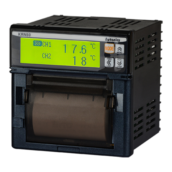
The invisible hand for more convenient world sensors & controllers 50mm Small Hybrid Recorder KRN50 Series USER MANUAL KRN50 Series Thank you for choosing our Autonics products. Please read the following safety considerations before use. - Page 2 © Copyright Reserved Autonics Co., Ltd.
- Page 3 Preface Preface Thank you for purchasing Autonics product. Please familiarize yourself with the information contained in the Safety Considerations section before using this product. This user manual contains information about the product and its proper use, and should be kept in a place where it will be easy to access.
- Page 4 ● The manual’s content may vary depending on changes to the product’s software and other unforeseen developments within Autonics, and is subject to change without prior notice. Upgrade notice is provided through out homepage. ● We contrived to describe this manual more easily and correctly.
- Page 5 Failure to follow instructions can result in serious injury or death. Failure to follow instructions can lead to a minor injury or product damage. An example of the concerned feature's use. ※ 1 Annotation mark. © Copyright Reserved Autonics Co., Ltd.
-
Page 6: Safety Considerations
Failure to follow this instruction may result in electric shock. ● Ground F.G. terminal individually and ground cable should be over AWG16 (1.25mm Failure to follow this instruction may result in electric shock. © Copyright Reserved Autonics Co., Ltd. - Page 7 Failure to follow this instruction may result in fire or explosion. ● Check the polarity of the measurement input contact before wiring the temperature sensor. Failure to follow this instruction may result in fire or explosion. © Copyright Reserved Autonics Co., Ltd.
- Page 8 Attach noise filter on the grounded panel, etc. Use short cables for noise filter output part and power terminal of the unit. Failure to follow this instruction may result in product damage, malfunction by surge. viii © Copyright Reserved Autonics Co., Ltd.
-
Page 9: Table Of Contents
Panel mounting ............ 26 6� Functions ��������������������������������������������������������������������������������27 7� General operation and parameter setting menu ���������29 7�1 Operation mode ..............29 7�2 Operation procedure ............29 7�3 Setting keys ................30 7�4 Parameter ................33 © Copyright Reserved Autonics Co., Ltd. -
Page 10: Table Of Contents
Display information function ....... 78 9� Communication ���������������������������������������������������������������������83 9�1 Modbus address map ............85 10� Comprehensive device management program (DAQMaster) �����������������������������������������������������������������������91 10�1 Overview .................. 91 10�2 Features ................... 92 10�3 Dedicated function for KRN50 ......... 93 © Copyright Reserved Autonics Co., Ltd. -
Page 11: Overview
(shunt)) ● 2-channel simultaneous recording in graphic mode and digital mode ● High visibility and easy setting by LCD dot matrix ● Supports various option I/O function ● Small size (W96×H96×L100 mm), light weight © Copyright Reserved Autonics Co., Ltd. -
Page 12: Component And Sold Separately
KRN50 Mounting Bracket User manual Chart paper Resistance (50Ω) Before using KRN50, check the component. If any component is left out or damaged, contact our company or seller. Autonics service center: +82-32-820-2356 to 7 © Copyright Reserved Autonics Co., Ltd. -
Page 13: Sold Separately
1� Overview 1�2�2 Sold separately SCM-38I SCM-US48I (RS232C to RS485 converter) (USB to RS485 converter) SCM-US (USB to Serial converter) SCM-38I (RS232C/RS485 converter) and SCM-US48I (USB/RS485 converter) are same appearance. © Copyright Reserved Autonics Co., Ltd. -
Page 14: Ordering Information
※ 1. When selecting this for 2 CH model, two alarm outputs for CH1 are available. In other words, you cannot set one for CH1 and one for CH2. ※ 2. It is selectable only for 2 CH model. © Copyright Reserved Autonics Co., Ltd. -
Page 15: Part Descriptions
: Displays input channel of currently displayed PV on the PV display part. ⑩ PV display part : In RUN mode, displays PV of the current channel. In setting mode, displays parameters and mode setting values. ⑪ Unit display part: Unit of relevant channel is indicated. © Copyright Reserved Autonics Co., Ltd. - Page 16 (RUN) ⑮ PC loader port : It is a PC loader port for serial communication to set or monitor parameters by PC. Used to connect SCM-US (USB to Serial converter, sold separately). © Copyright Reserved Autonics Co., Ltd.
- Page 17 (charging terminal of the other polarity) 0.75mm amplitude at frequency of 10 to 55 Hz Vibration (for 1 min) in each X, Y, Z direction for 1 hour Mechanical: Over 5,000,000 operations, Relay life cycle Electrical: Over 100,000 operations © Copyright Reserved Autonics Co., Ltd.
- Page 18 ● All thermocouples, below -100 ℃ : (±0.4% F.S.) ±1-digit ※ 2. The weight includes packaging. The weight in parenthesis is for unit only. ※ Environment resistance is rated at no freezing or condensation. © Copyright Reserved Autonics Co., Ltd.
-
Page 19: Input Type And Range
(display range depends on the -1.00 - 10.00V decimal point position) 0 - 20mA 0-20 Current (shunt) 4 - 20mA 4-20 ※ 1. C(TT): Same as exisitng W5(TT). ※ 2. G(TT): Same as exisitng W(TT). © Copyright Reserved Autonics Co., Ltd. - Page 20 2. Specifications © Copyright Reserved Autonics Co., Ltd.
- Page 21 3� Dimensions 3� Dimensions (unit: mm) M3 Screw type terminal 100.5 ● Panel cut-out (96×(N-1)+92) +0.5 Parallel mounting ·N = Quantity ·Panel thickness: 1 to 4 mm © Copyright Reserved Autonics Co., Ltd.
- Page 22 3� Dimensions © Copyright Reserved Autonics Co., Ltd.
- Page 23 ※ The DC power model does not have F.G. ※ When using 2-wire RTD, short B and b terminals. ※ For current input, external 50Ω B class (0.1%) high-accuracy resistor. © Copyright Reserved Autonics Co., Ltd.
- Page 24 4� Connections © Copyright Reserved Autonics Co., Ltd.
-
Page 25: Environment
You should warm-up this unit over 30 min to acquire accurate data before using it. ● At the place where temperature and humidity is fluctuated excessively, recording paper color may be changed. © Copyright Reserved Autonics Co., Ltd. -
Page 26: Installation Method
When RTD lead wire need to extend, please use it with small resistance value and be equal for resistive value to 3 lead wires. Connect wiring after power off in order to prevent from electric shock. Check input specifications in order to prevent from any damages. © Copyright Reserved Autonics Co., Ltd. - Page 27 Feeding function and recording run/stop function are able to be used by front key or communication at the status of recording stop. Also recording reservation function is able to start or stop recording at the suitable time period user wants. © Copyright Reserved Autonics Co., Ltd.
- Page 28 6� Functions © Copyright Reserved Autonics Co., Ltd.
-
Page 29: Operation Mode
Set relevant parameter (input type, alarm, record speed) according to input sensor. ● Record and display measuring value If necessary, press key for recording Run / Stop. Also mode is able to be changed by measuring value display mode relevant key. © Copyright Reserved Autonics Co., Ltd. -
Page 30: Setting Keys
If entering into the setting category at the lower setting menu, the cursor flashes on the setting category. Then, user is able to change the setting category by means of key. © Copyright Reserved Autonics Co., Ltd. - Page 31 If pressing key for 3 sec when the cursor is placed at the lower setting menu, it is able to move to the setting mode from general operation mode and operate according to setting value. © Copyright Reserved Autonics Co., Ltd.
- Page 32 Especially the fourth position of number is able to change to either number or sign. If pressing key at the status of wrong value and save it when changing setting value, it indicates Error code as above. © Copyright Reserved Autonics Co., Ltd.
-
Page 33: Parameter
Stop Backup data ] is 4 3 key For 2 CH model ( key set as 「Yes」 . Graph Environment Setup Display Mode Digital ※ Parameter setup model: All models Backlight Cancel Setting Lock © Copyright Reserved Autonics Co., Ltd. - Page 34 7� General operation and parameter setting menu © Copyright Reserved Autonics Co., Ltd.
-
Page 35: Recording Preparation
Then if the cursor flashes at the position for change, moving the cursor by key and setting the value by key. After then if pressing key, setting value is saved. iv. Time setting method is same as 3rd. © Copyright Reserved Autonics Co., Ltd. -
Page 36: Explanation For Input Function And Setup
Regarding saved data by record backup, if CH1,2 Record: ON, OFF function is changed, previous record backup data is removed and start saving the data from the current modified time. Therefore please be careful for setup. © Copyright Reserved Autonics Co., Ltd. - Page 37 ● Factory default: TC-K1 (unit: - ) If changing input type, saved data by record backup is removed and it starts saving the data from the modified current time. Therefore please be careful for setup. © Copyright Reserved Autonics Co., Ltd.
- Page 38 This function is to set low-limit scale value of graph within input range of each input type. ● Setting range: Min. range by each sensor input type to Graph high limit scale value[ CH Hi Graph ]- F.S. 5% ● Factory default: -200(unit: Digit) © Copyright Reserved Autonics Co., Ltd.
- Page 39 In case of temp. sensor input (TC, RTD), this function is to set graph scale value for record to chart paper and user voluntarily is able to as- sign the recording range. If specified indicating section is recording in detail by graph curve, it is used. © Copyright Reserved Autonics Co., Ltd.
- Page 40 This function is to assign and limit the actual using low-limit input value within input range. ● Setting range: Min. input range to high-limit input value[CH Range]- F.S 5% ● Factory default: Min. input range (unit: -) © Copyright Reserved Autonics Co., Ltd.
- Page 41 Graph scale of chart paper is applied one-to-one according to setting scale value (High/Low-limit scale value). (E.g.: in case of –1 to 10V input type, to process from 0 to 5V input , set low-limit input value:0, high-limit input value:5.) © Copyright Reserved Autonics Co., Ltd.
- Page 42 ● Factory default: 100.0 (unit: Digit) Display scale function is able to change display value for max./min. measured input by setting high-limit scale [ Hi Scale ] and low-limit scale [ Lo Scale ]. © Copyright Reserved Autonics Co., Ltd.
- Page 43 DP Unit] is not indicated. us0 to us9 is used to apply user font unit with 16×16 size (32byte) font. User font unit is written through RS485 communication. (Communication program, DAQMaster, has user unit setup and download function.) © Copyright Reserved Autonics Co., Ltd.
- Page 44 $ recently, when data output by record backup, previous data with # unit also records with recent unit $. Therefore one user font unit (us0 to us9) should be used for several units. © Copyright Reserved Autonics Co., Ltd.
- Page 45 Sc Point: 0 In Bias: -999 to 999 Sc Point: 0.0 In Bias: -99.9 to 99.9 Sc Point: 0.00 In Bias: -9.99 to 9.99 Sc Point: 0.000 In Bias: -0.999 to 0.999 ● Factory default: 0000 (unit: Digit) © Copyright Reserved Autonics Co., Ltd.
- Page 46 ↔ K ↔ L ↔ M ↔ N ↔ O ↔ P ↔ Q ↔ R ↔ S ↔ T ↔ U ↔ V ↔ W ↔ X ↔ Y ↔ Z ↔ = ● Factory default: CH- (unit: -) © Copyright Reserved Autonics Co., Ltd.
-
Page 47: Alarm Function Setup
During recording, when alarm operation, current time, PV, alarm information (AL HI =↑, AL LO =↓, SBA = B, P.End = P) print to chart paper. HI, LO of AL1, AL2 in printed AL1(↑↓) AL2( ) for classify AL1 and AL2 separately. © Copyright Reserved Autonics Co., Ltd. - Page 48 (standard alarm) and P is printed on recording paper when printing back up data. Recording mark: AL1= P AL2= P ● Factory default: CH AL1 Type(PV.Hi), CH AL2 Type(PV.Lo) © Copyright Reserved Autonics Co., Ltd.
- Page 49 Sensor break is able to be checked through buzzer or other devices by means of external alarm contact. If alarm output operation mode sets to SBA, sensor break alarm will be operated. ※ 10V input is not applied for SBA. © Copyright Reserved Autonics Co., Ltd.
- Page 50 Low], when burn operate by sensor open, alarm operation will be ● Setting range: Within using/display range by input type ● Factory default: [CH AL Lo]: Low-limit scale value Hi]: High-limit scale value (unit: ℃ / ℉ ) [CH AL © Copyright Reserved Autonics Co., Ltd.
- Page 51 As alarm output hysteresis, ‘hysteresis’ sets the interval between ON and OFF of alarm output. ● Setting range: 001 to 999 (decimal point is placed same as input decimal point) ● Factory default: 001 (unit: Digit) © Copyright Reserved Autonics Co., Ltd.
- Page 52 Once alarm output is on, it will hold on even out of alarm output range. (Alarm output hold) Cancellation condition: If need to cancel alarm latch function, please press key for over 3 sec after current PV is lower than alarm value. © Copyright Reserved Autonics Co., Ltd.
- Page 53 1, AL1 low-limit: 100 ℃ , Alarm option: None / AL2 high-limit: 600 ℃ , Alarm option: None. For record mode, Record mode: graph mode, Recording speed: 960mm/h, Memo period: 1min If setup is as above, recording will be as follows. © Copyright Reserved Autonics Co., Ltd.
- Page 54 CH1 input type and entering into the setting category, set to ‘TC-K1’ and press key to get out of this menu. iii. Input High/Low graph range setup Set CH1 Lo Graph:0, CH1 Hi Graph:1000 at the lower menu of input type setup. © Copyright Reserved Autonics Co., Ltd.
- Page 55 Set Record mode: Graph, Rec speed: 960mm/h, Memo period: 1min ix. After completing all setup, if pressing key for 3 sec, it moves to operating mode and processes as above setting value. © Copyright Reserved Autonics Co., Ltd.
- Page 56 None / AL2 Low-limit: 20.0ppm, Alarm option: None. For record mode, Record mode: graph mode, Recording speed: 960mm/h, Memo period: 1min (Record mode setup is same as Example 1)If setup is as above, recording will be as follows. © Copyright Reserved Autonics Co., Ltd.
- Page 57 ‘4 to 20mA’ and set CH2 Dp unit to ‘ppm’ and press key to get out of this menu. iii. Input High/Low scale setup Set CH2 Lo Scale:000.0, CH2 Hi Scale:100.0 at the lower menu of input type setup. © Copyright Reserved Autonics Co., Ltd.
- Page 58 After setting CH2 AL1 type: PV.Hi and saving it by pressing key, set AL1 Opt: None, AL1 High: 20.0. vi. After setting CH2 AL2 type: PV.Lo and saving it by pressing key, set AL2 Opt: None, AL2 Low: 70.0. © Copyright Reserved Autonics Co., Ltd.
-
Page 59: Recording Setup
When RUN, “>>>” lamp is lightening. When STOP, “■” lamp is lightening. Once power ON, recording is able to Run or Stop automatically when re-power ON after electricity failure or by user according to recording run/stop parameter (PWR On State). © Copyright Reserved Autonics Co., Ltd. - Page 60 3 sec. The latest record is placed behind of paper cutter at STOP state therefore cut the chart paper after manual paper feeding in order to check the latest record. © Copyright Reserved Autonics Co., Ltd.
- Page 61 Digital memo period is printing at the basis of regular time. ● Setting range: Digital memo period setting range is limited according to recording speed as following table. ● Factory default: 30 (unit: min)(O: enable to set, X: disable to set) © Copyright Reserved Autonics Co., Ltd.
- Page 62 If digital memo period is 15 min and recording start time is ‘09:34’, the first digital memo time recording is not ‘09:49’ but ‘09:45’ at the basis of regular time. Recording time - 09:45 → 10:00 → 10:15 → 10:30 → 10:45 → Until recording end) © Copyright Reserved Autonics Co., Ltd.
- Page 63 Recording speed: 960mm/h, Memo period: 30 sec, Alarm Speed: 120mm/h In case that alarm does not operate, when recording during per 960mm/h, 30 sec alarm occurs, it records per 120mm/h, 5 min. © Copyright Reserved Autonics Co., Ltd.
- Page 64 If returning to operating mode after setting reservation function on the setting mode, recording is stopped and the reservation record lamp (RE) is lighting on display. © Copyright Reserved Autonics Co., Ltd.
- Page 65 (12) Recording start time (Start Time) Set the recording start time. ● Setting range: 00:00 to 23:59 (13) Recording stop time (Stop Time) Set the recording stop time. ● Setting range: 00:00 to 23:59 © Copyright Reserved Autonics Co., Ltd.
- Page 66 8� Recording © Copyright Reserved Autonics Co., Ltd.
- Page 67 In case of no relay contact, it needs to use NPN open collector output type contact and in case of relay contact, it needs to use contact small current(0.2mA) is able to be flowed enough. © Copyright Reserved Autonics Co., Ltd.
- Page 68 (17) Printing the setting list when record start [RUN On State] This function is to set printing the setting list when record start simultaneously. It is divided into List and Off. ● Setting range: List / Off ● Factory default: Off(unit: -) © Copyright Reserved Autonics Co., Ltd.
- Page 69 If alarm mode sets to paper end function, P.ED lamp will lighten and alarm output will be on simultaneously. When changing chart paper, if sensing chart paper, the unrecorded data of since the time of exhausting chart paper is able to be recorded and printed. © Copyright Reserved Autonics Co., Ltd.
- Page 70 If chart paper is exhausted during RUN state, it will be changed to STOP state automatically. When user changes chart paper, message for re-recording function about unrecorded data is indicated on display and user is able to select the recording range. © Copyright Reserved Autonics Co., Ltd.
- Page 71 8� Recording © Copyright Reserved Autonics Co., Ltd.
- Page 72 (for example, recording time of digital mode is set to 5 min, the interval of saving backup data is every 5 min and stop time is changed every 5 minas well.) © Copyright Reserved Autonics Co., Ltd.
- Page 73 Input type setup: CH1 or 2 Record, CH1 or 2 In type, When analog input, CH1 or when changing 2 Lo,Hi scale setting Date/ Time setup: When changing date or time setting ● Setting range: Cancel / Yes (unit: -) ● Factory default: Cancel © Copyright Reserved Autonics Co., Ltd.
- Page 74 Approx. 25 hours 1 min 60 sec Approx. 8 days Approx. 12 days 60 min 3600 sec Approx. 480 days Approx. 755 days 99 min 59 sec 6000 sec Approx. 800 days Approx. 1259 days © Copyright Reserved Autonics Co., Ltd.
- Page 75 8� Recording © Copyright Reserved Autonics Co., Ltd.
- Page 76 PV again. Record parameter: Tag name, Input, Unit, Range, Scale, Alarm mode, Alarm setting value, Communication function When starting record, parameter setting information is able to be recorded according to printing the setting list parameter. © Copyright Reserved Autonics Co., Ltd.
- Page 77 8� Recording © Copyright Reserved Autonics Co., Ltd.
-
Page 78: Display Information Function
P.End, it will be indicated. If start time and stop time are same on Set!! reservation record function, it will be indicated. If pressing key, it will be cancelled and returned to previous setting state. © Copyright Reserved Autonics Co., Ltd. - Page 79 If setting one channel record only [Input type setup group >> CH1 or CH2 Record ‘Off’], 1 channel display mode is fixed and indicated. ● Setting range: 2CH / 1CH (unit: -) ● Factory default: 2CH © Copyright Reserved Autonics Co., Ltd.
- Page 80 During light down state, if operating front key, it will lighten automatically. If no key input for 30 sec after final front key operation, it will light down automatically. © Copyright Reserved Autonics Co., Ltd.
- Page 81 Even though selecting [Loc1],[Loc2],[Loc3], [Setting Lock] parameters will be always indicated and it will be changed. ● Factory default: Off (unit: -) Even though setting parameter lock function up, parameter will be initialized by parameter initializing function. © Copyright Reserved Autonics Co., Ltd.
- Page 82 If pressing key for 5 sec simultaneously, it will operate. ● Setting range: Yes / No ● Factory default: No (unit: -) © Copyright Reserved Autonics Co., Ltd.
- Page 83 KRN50 recorder is able to communicate through back terminal or front phone jack. In case of back terminal connection. Front and back communication functions are not used simultaneously. (use autonics SCM-US (sold separately) for communicating by front communication port.) In case of phone jack communication, there may be reorganization error due to external noise or environment during connecting PC.
- Page 84 Communication setting is fixed as communication speed: 9600bps, communication respond waiting time: 0.05sec, Start bit: 1-bit, Stop bit: 2-bit, Parity bit: None. © Copyright Reserved Autonics Co., Ltd.
-
Page 85: Modbus Address Map
High parameters are not displayed. CH AL Type(PV.Hi): CH AL High parameter is not displayed. CH AL Type(PV.Lo): CH AL Low parameter is not displayed. ※ 2. It displays only for 2 channels alarm output model. © Copyright Reserved Autonics Co., Ltd. - Page 86 13: mmHg, 14: mmH ※ 2 CH1 DP Unit 40312 CH 1 record display unit 15: User1, 16: User2, 17: User3, 18: User4, 19: User5, 20: User6, 21: User7, 22: User8, 23: User9, 24: User0, 25: OFF © Copyright Reserved Autonics Co., Ltd.
- Page 87 Record speed for alarm 4: 240, 5: 480, 6: 960 hour ※ 1. Displays only when record mode (Rec Mode) is set as ‘Graph’. ※ 2. Displays only when record mode (Rec Mode) is set as ‘Digital’. © Copyright Reserved Autonics Co., Ltd.
- Page 88 0: Displays 2 channels, ※ 1 Display standard mode 1: Display per 1 channel in turn automatically 0: Off, 1: Loc1, Setting Lock 40066 Lock 2: Loc2, 3: Loc3 Backlight 40067 Temp Backlight 0: Temp, 1: Always © Copyright Reserved Autonics Co., Ltd.
- Page 89 Serial No L 30103 Software Version 30104 Hardware Version 30105 Model Name 1 "KR" 30106 Model Name 2 "N5" 30107 Model Name 3 "0- " 30108 Model Name 4 "X0 " X: marked by the model © Copyright Reserved Autonics Co., Ltd.
- Page 90 ※ 2. Unit and Unit group values are used at user unit download function of the comprehensive device management program (DAQMaster). ※ 3. Download user images such as unit, and logo, etc. (Refer to 10.3 Dedicated function for KRN50 (2) Downloading User Images.) © Copyright Reserved Autonics Co., Ltd.
- Page 91 10�1 Overview DAQMaster is a comprehensive device management program that can be used with Autonics thermometers, panel meters, pulse meters, counters, recorders, and indicators, etc. DAQMaster provides GUI control for easy and convenient management of parameters and multiple device data monitoring.
-
Page 92: Features
Supports Korean, English, Japanese, Simplified Chinese. To add a different language, modify the files in the Lang folder, rename, and save. ● Script Support Uses the Lua Script language and deals with different I/O processes for individual devices. © Copyright Reserved Autonics Co., Ltd. -
Page 93: Dedicated Function For Krn50
Backup in the Property window. To read memory information, the device status must be Connected and not Run. There are also cases in which you cannot read from memory depending on KRN50 parameter setting. © Copyright Reserved Autonics Co., Ltd. - Page 94 You can cancel the operation while data is being uploaded. When data reading is complete, OK button is enabled. v. If you click OK, recorded data will be shown in two screens - the Grid and the Graph. © Copyright Reserved Autonics Co., Ltd.
- Page 95 You can also reset images back to the original status. This is also a self protocol, so cannot download images during Run. Download logo You can change the company logo image on contents that are printed on recording paper. Logo image should be 384×80 pixel of bitmap file. © Copyright Reserved Autonics Co., Ltd.
- Page 96 Download Units There are 0 to 9 user units. The download procedure is: select a unit list → select a destination to save → double-click a unit image to add the image → download. © Copyright Reserved Autonics Co., Ltd.
- Page 97 The boot image (logo image) appears on LCD upon initial power supply to KRN50. You can change booting logo image which displays when KRN50 is power ON. The image should be 128×32 pixel of bitmap file. © Copyright Reserved Autonics Co., Ltd.
- Page 98 #402-303, Bucheon Techno Park, 655, Pyeongcheon-ro, Wonmi-gu, Bucheon, Gyeonggi-do, South Korea 14502 Tel: 82-32-610-2730 / Fax: 82-32-329-0728 / E-mail: sales@autonics.com ■ Brazil − Autonics do Brasil Comercial Importadora Exportadora Ltda Tel: 55-11-2307-8480 / Fax: 55-11-2309-7784 / E-mail: comercial@autonics.com.br ■ China − Autonics electronic(Jiaxing) Corporation Tel: 86-21-5422-5969 / Fax: 86-21-5422-5961 / E-mail: china@autonics.com...
Need help?
Do you have a question about the KRN50 SERIES and is the answer not in the manual?
Questions and answers