
Related Manuals for EOS ECON D3


Summary of Contents for EOS ECON D3
- Page 1 ECON D3 Sauna control unit Installation and operating instruction Made in Germany IP x4 Print no. 29344726en / 27.15...
-
Page 2: Table Of Contents
English Table of Contents Scope of delivery ............................4 Technical specifications ..........................4 General information about sauna bathing ..................5 General safety precautions ........................6 Mechanical installation of the control unit Installation place .............................8 Surface-mounting installation ......................8 Semi-recessed installation ........................9 Connecting the temperature sensor cables ................10 Installation and connection of the temperature sensor ............ - Page 3 Cabin temperature ........................24 Life - Guard ............................24 Auto-Stop (heating time limitation) ..................25 Preselection time (pre-set timer) ....................27 Activate the preselection time ....................28 Deactivate the preselection time ..................... 28 Extend the time setting for sauna time ....................29 Unit fuses ...............................
-
Page 4: Scope Of Delivery
Scope of delivery (changes without prior notice reserved) The package contents includes: Control unit 1. Temperature sensor, consisiting of: sensor board with overheating protection fuse, KTY-sensor, sensor housing, two 3x25 mm fastening screws and 2,0 m long sensor cable. 2. Plastic bag with three 4 x 20 mm fastening screws. 3. -
Page 5: General Information About Sauna Bathing
Dear customer General information You have purchased a high-quality technical Please check whether the unit has arrived in per- device with which you will have years of sauna fect condition. Any transport damages should be fun. This sauna control unit was designed and immediately reported to the freight forwarder inspected according to the current European delivering the goods or you should contact the... -
Page 6: General Safety Precautions
General safety precautions ature setting. The temperature can be held within operating parameters and This device can be used by children aged • a minimal temperature gradient inside 8 upwards and by persons with physical, the bench area of the sauna cabin can be sensory, or mental disabilities, or who achieved only if unit is assembled correct- have inadequate experience and knowl-... - Page 7 When designing the cabin ensure that the external exposed glass surfaces only re- ach a maximum temperature of 76°C. If ne- cessary, protective features need to be tted. Attention! Dear customer, according to the valid regulations, the electrical connection of the sauna heater and the control box has to be carried out through the specialist of an authorized electric shop...
-
Page 8: Mechanical Installation Of The Control Unit Installation Place
Fasten the housing bottom at the two bot- Installation of the control unit tom openings (Fig. 4) rmly to the cabin wall. Wall installation The control unit may only be mounted outside the sauna cabin. It is advisable to select the out- ca. -
Page 9: Semi-Recessed Installation
Recessed installation 1. Cut out a wall section that is at least 3.5 cm deep according to the dimension in Fig. 5. 21 cm Fig. 5 Insert the supplied rubber grommets into the openings at the rear wall of the housing and insert the connecting cables through these openings. -
Page 10: Connecting The Temperature Sensor Cables
Connection of the sensor cables 20 cm You should not lay sensor and power supply ca- bles together, or draw them through the same feedthrough. This can lead to interferences in the electronics, such as “ uttering” in the relays, which may damage the control unit. -
Page 11: Installation And Connection Of The Second Sensor (Bench Sensor)
Hole Jumper for heating time limitation setting: 6 h, 12 h, unlimited Sauna ceiling centre sensor housing in the middle of the plank Second temperature sensor (optional) L1 L2 L3 N W V U N sensor cables Fig. 11 Attention! Make sure not to confuse the sensor cables at X2 connector! This may cause 142°C... - Page 12 Installation of the optio- nal second temperature sensor (bench sensor) Installation place: The bench sensor shall be By faults of the second sensor the following er- mounted to the ceiling over the rear wall bench ror messages will be displayed: opposite to the heater as described in the in- „Sensor break“...
-
Page 13: Electrical Connections
Electrical connection Connection of the power The electrical connections may only be car- ried out by a certi ed electrician in compli- extension unit (LSG) ance with the guidelines of the local power supply company and applicable legal regu- For details refer to the installation instructions lations (e.g. -
Page 14: Installation Diagram
Installation diagram = optional ECON 400 V 3 N AC 50 Hz Terminal layout on the main board Jumper for heating time limitation Connector for tempera- ture sensor Connection for the 2nd temp. sensor L1 L2 L3 N W V U N... -
Page 15: Connection Of Sauna Heaters Up To 9 Kw
Connection of sauna heaters up to 9 kW 142°C ECON L1 L2 L3 V1 N S1 Limiter weiß / white Sensor rot / red max. 100 W Attention! Always connect the N terminal of the sauna heater! P max. 9 kW 400 V 3 N AC 50 Hz Connection of sauna heaters above 9 kW 142°C... -
Page 16: Operation
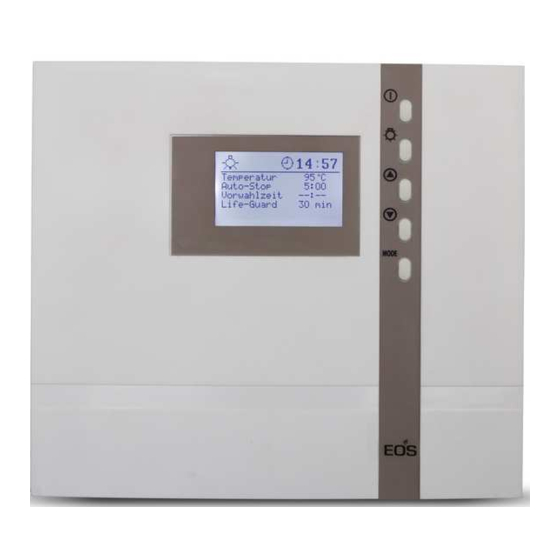
Operation Once the control unit has been installed with all components and all covers have been xed, you can put your sauna unit into operation. The following pages provide the detailed explanation, how to operate your control panel and make all necessary settings. General details Operation elements MODE... -
Page 17: Interface In Stand-By
Interface in Stand by is shown if the control unit is in stand-by model 12:00 Temperature 30°C The display will automatically switch this in- Auto-stop 5 : 59 terface from any state if no button has been Start time - - : - - pressed within >15 Sek. -
Page 18: Cabin Lighting
In order to adjust the individual values to the particular desires, brie y push the -but- MODE ton out of Stand-by. 12:15 The modi able parameter will then be high- Temperature 30°C Auto-stop 5 : 59 lighted in black and it is possible to select with - - : - - Start time - buttons the desired parameter. -
Page 19: Initial Commissioning
Initial commissioning 12:00 12:15 Life Guard 12:00 12:15 Life - Guard > 3 Sek MODE 00:00 Time of day > 3 Sek MODE : 00 12:00 Temperature 30°C Auto-stop 5 : 59 Start time - - : - - 20 min Life - Guard 00:00 Time of day... -
Page 20: Change Language
Change language Set (change) time 12:00 12:00 Temperature 30°C Temperature 30°C Auto-stop 5 : 59 Auto-stop 5 : 59 Start time - - : - - Start time - - : - - & & MODE MODE 12:00 12:15 Time of day Time of day 12 : 00 12 : 15... -
Page 21: Activate The Life - Guard
Activate Life-Guard function Activate / deactivate the child lock Life-Guard is a settable relatively short time, If the child lock is activated (the key symbol is e.g. 20 minutes, after which the sauna heater visible in the top section of the display) only the will be switched o , except for the cabin ligh- cabin lighting can be switched. -
Page 22: Switching On The Sauna Heater
Switching on the sauna heater Switching the heater with Life- Guard function 12:00 12:00 Temperature 30°C Temperature 30°C Auto-stop Auto-stop 5 : 59 5 : 59 Start time Start time - - : - - - - : - - 20 min Life - Guard >... -
Page 23: Individual Settings
Individual settings Hereafter we are showing you the options that allow you to adjust the controls to your individual needs. The various parameters can be changed in Stand-by or in operation and the changes are saved in the unit. Changes in settings made during operation will be applied directly as they are made. -
Page 24: Cabin Temperature
Life-Guard Here you can set after what time the sauna heater shall be switched o and by pushing the MODE - button again you can restart the heating for the pre-set “Life-Guard” time. This setting can only be selected in Stand-by when the function “Life - Guard” is activated. For instance you set 15 min time. -
Page 25: Auto-Stop (Heating Time Limitation)
Auto-Stop (heating time limitation) Auto-Stop is the time to which the heating time is limited. The sauna heater automatically turns o once this time has expired. The time is adjustable from 0:01 to 6:00 hours. The extension of this time is possible with the jum- per setting and may be carried out only the specialist dealer. - Page 26 12:15 12:15 Temperature 30°C Temperature 30°C Auto-stop Auto-stop - - : - - - - : - - Start time Start time > 3 sec. > 3 sec MODE MODE 12:00 12:15 Temperature 30°C Temperature 30°C Auto-stop Auto-stop 3 : 30 3 : 30 - - : - - Start time...
-
Page 27: Preselection Time (Pre-Set Timer)
Preselection time (pre-set timer) Using the time preselection, you can preselect a switch-on time within 24 hours in advance for your sauna heater. Always make sure that there are no objects on the sauna unit before the heating process begins. Fire risk! Please remember that a typical sauna cabin must heat up for approx. -
Page 28: Activate The Preselection Time
12:15 12:15 Temperature 30°C Temperature 30°C Auto-stop 5 : 59 Auto-stop 5 : 59 17 : : - - Start time Start time 12:15 12:15 Temperature 30°C Temperature 30°C Auto-stop 5 : 59 Auto-stop 5 : 59 Start time 17 : Start time 17 : >... -
Page 29: Extend The Time Setting For Sauna Time
Extend heat-up time restriction / replace device fuse By switching a jumper you can extend the time setting for sauna time from 6:00 to 12:00 hours or to unlimited operation time. Please notice that such extension is only permitted for certain com- mercial sauna cabins and may be restricted by the local legal regulations. -
Page 30: Error Messages And Troubleshooting
Error messages The control unit continuously monitors the sensor for short circuits and interruptions. At the same time, the system checks to ensure that there is enough water in the vaporizer tank. The error messages appear as follows: Display Cause Remedy = interrupted room sensor circuit Arrange for a specialist to... -
Page 31: The Device Switch (Switch-Off )
The device „Switch-o “ switch Switch-o by ECON control units You will nd the rocker switch on the top side of the control unit. You can completely discon- nect the control unit from the mains using this switch. Switch-o Unit turned on (default Position I) Press the switch on the left side of the rocker Unit fully switched o... -
Page 32: Service Address
Outside of Germany please contact your spe- Service Address: cialist dealer in case of warranty claims. Direct warranty processing with our service depart- EOS Saunatechnik GmbH ment is in this case not possible. Schneiderstriesch 1 35759 Driedorf, Germany Equipment commissioning date:... -
Page 33: General Terms And Conditions Of Service
shipments via parcel post. The manufacturer shall accept General Terms and Conditions of Service no liability for damage incurred as a result of improper I. Scope packaging in an individual shipment. Unless otherwise agreed in writing in a speci c case, the- VI.
Need help?
Do you have a question about the ECON D3 and is the answer not in the manual?
Questions and answers