
Related Manuals for Alcatel-Lucent OmniSwitch 6855-24


Summary of Contents for Alcatel-Lucent OmniSwitch 6855-24
- Page 1 Part No. 060232-10, Rev. B March 2009 OmniSwitch 6855 Series Hardware Users Guide www.alcatel-lucent.com...
- Page 2 The specifications described in this guide are subject to change without notice. Copyright © 2008 by Alcatel-Lucent. All rights reserved. This document may not be reproduced in whole or in part without the express written permission of Alcatel-Lucent.
-
Page 3: Table Of Contents
Hardware Monitoring ....................1-5 Backup Power Supplies ....................1-5 Chapter 2 OmniSwitch 6855 Series Chassis and Hardware Components ..... 2-1 OmniSwitch 6855 Chassis Configurations ..............2-1 OmniSwitch 6855-24 ......................2-4 OmniSwitch 6855-U24 ....................2-7 OmniSwitch 6855-14 ....................2-10 OmniSwitch 6855-U10 ....................2-13 Status LEDs ........................2-16 Rear Panel ........................2-18 OS6855-24/OS6855-U24 ..................2-18... - Page 4 Contents PS-126I80AC Power Supply ..................2-22 PS-360I160AC-P Power Supply ................2-23 PS-120I80DC48 Power Supply ................2-25 PS-100I80DC24 Power Supply ................2-26 OS6855-14/U10 Power Supplies ..................2-27 PS-I40AC Power Brick ..................2-29 PS-I66AC-P PoE Power Brick ................2-30 PS-I40DC2448 Power Brick ..................2-31 PS-I40DC2448E Power Brick ................2-32 PS-75I42DC48-P PoE Power Brick ...............2-33 UL Recognized Power Supply Table ................2-34 Power Supply Shelf ....................2-35 OS6855-24/U24 ....................2-35...
- Page 5 Contents Rack Mounting Steps .....................3-12 Table Mounting the Chassis ..................3-14 Chapter 4 Mounting OS6855-14 and OS6855-U10 Switches ..........4-1 Chassis Components ....................4-1 General Installation Recommendations ................4-2 Cooling Recommendations ..................4-2 Recommended Clearances ..................4-3 Mechanical Loading ....................4-3 Circuit Overloading ....................4-3 Reliable Earthing ......................4-3 Power Supply Information ....................4-4 Rack-Mounting OS6855-14 and OS6855-U10 Switches ..........4-5 General Rack-Mounting Guidelines .................4-5...
- Page 6 Contents Configuring Power over Ethernet Parameters ..............6-5 Power over Ethernet Defaults ..................6-5 Understanding and Modifying the Default Settings ..........6-5 Setting the PoE Operational Status ..............6-5 Configuring the Total Power Allocated to a Port ..........6-6 Configuring the Total Power Allocated to a Switch .........6-6 Setting Port Priority Levels ................6-7 Understanding Priority Disconnect .................6-8 Setting Priority Disconnect Status ................6-8...
- Page 7 Contents Instrucciones de seguridad en español ................. A-16 Advertencia sobre el levantamiento del chasis ..........A-16 Advertencia de las tapaderas en blanco ............A-16 Advertencia en caso de tormenta eléctrica ............. A-16 Advertencia de instalación ................A-16 Advertencia de radiación láser invisible ............A-16 Advertencia de la batería de litio ..............
- Page 8 Contents viii OmniSwitch 6855 Series Hardware Users Guide March 2009...
-
Page 9: About This Guide
About This Guide This OmniSwitch 6855 Series Hardware Users Guide describes your switch hardware components and basic switch hardware procedures. Supported Platforms This information in this guide applies to the following products: OmniSwitch 6855-24 • OmniSwitch 6855-U24 • OmniSwitch 6855-14 •... -
Page 10: Supported Platforms
Supported Platforms About This Guide Unsupported Platforms The information in this guide does not apply to the following products: OmniSwitch (original version with no numeric model name) • OmniSwitch 6600 Family • OmniSwitch 6800 Series • OmniSwitch 6850 Series • OmniSwitch 7700 •... -
Page 11: Who Should Read This Manual
About This Guide Who Should Read this Manual? Who Should Read this Manual? The audience for this users guide is network administrators and IT support personnel who need to config- ure, maintain, and monitor switches and routers in a live network. However, anyone wishing to gain knowledge on the OmniSwitch 6855 Series hardware will benefit from the material in this guide. -
Page 12: How Is The Information Organized
How is the Information Organized? About This Guide How is the Information Organized? This users guide provides an overview of OmniSwitch 6855 Series switches, specifications of the hard- ware components, steps for setting up and managing OmniSwitch 6855 Series switches, and an overview and procedures for managing Power over Ethernet (PoE). - Page 13 About This Guide Documentation Roadmap Stage 3: Integrating the Switch Into a Network Pertinent Documentation: Network Configuration Guide Advanced Routing Configuration Guide When you are ready to connect your switch to the network, you will need to learn how the OmniSwitch implements fundamental software features, such as 802.1Q, VLANs, and Spanning Tree.
-
Page 14: Related Documentation
Includes SFP and XFP transceiver specifications and product compatibility information. Technical Tips, Field Notices • Includes information published by Alcatel-Lucent’s Customer Support group. Release Notes • Includes critical Open Problem Re, feature exceptions, and other important information on the features supported in the current release and any limitations to their support. -
Page 15: Published / Latest Product Documentation
Published / Latest Product Documentation Published / Latest Product Documentation All user guides for the OmniSwitch 6855 Series are included on the Alcatel-Lucent public website. This website also includes user guides for other Alcatel-Lucent Enterprise products. The latest user guides can be found on our website at: http://www1.alcatel-lucent.com/enterprise/en/resource_library/user_manuals/... - Page 16 Technical Support About This Guide page xvi OmniSwitch 6855 Series Hardware Users Guide March 2009...
-
Page 17: Omniswitch Os6855 Family
1 OmniSwitch OS6855 Family The Alcatel-Lucent OmniSwitch 6855 family of fixed configuration LAN switches are industrial-grade, managed, Gigabit Ethernet units are designed to operate reliably in severe temperatures, as well as harsh physical and electrical conditions. Note. Switches in the OmniSwitch 6855 family are fixed configuration, standalone units. Stacking multiple OS6855 switches into a virtual chassis is not supported. -
Page 18: Chassis Configurations
Chassis Configurations OmniSwitch OS6855 Family Chassis Configurations OmniSwitch 6855 (OS6855) “hardened” switches offer port densities of up to 24 Gigabit Ethernet ports. The following OS6855 chassis configurations are available: Fiber Models OS6855-U10: Provides eight (8) Gigabit Ethernet SFP ports and two (2) RJ-45 10/100/1000 ports. •... -
Page 19: Security Features
OmniSwitch OS6855 Family Security Features Security Features For their targeted high impact, mission critical applications, OS6855 switches offer extensive security features for network access control, policy enforcement and attack containment, enabling fully secure networks and OmniVista Network Management System (NMS) support. Applications Although well-suited for traditional enterprise network applications, the versatile OS6855 switches are built for high impact applications such as:... -
Page 20: Availability Features
OmniSwitch OS6855 Family Availability Features OS6855 switches incorporate advanced Alcatel-Lucent Operating System (AOS) protocols to ensure high availability for mission critical applications. Availability features are hardware- and software-based safe- guards that help to prevent the loss of data flow in the unlikely event of a subsystem failure. -
Page 21: Hardware Monitoring
OmniSwitch OS6855 Family Availability Features Hardware Monitoring Automatic Monitoring Automatic monitoring refers to the switch’s built-in sensors that automatically monitor operations. If an error is detected (e.g., over-threshold temperature), the switch immediately sends a trap to the user. The trap is displayed on the console in the form of a text error message. (In the case of an over-threshold temperature condition, the chassis displays an amber OK LED in addition to sending a trap.) LEDs LEDs, which provide visual status information, are provided on the chassis front panel. - Page 22 Availability Features OmniSwitch OS6855 Family page 1-6 OmniSwitch 6855 Series Hardware Users Guide March 2009...
-
Page 23: Chapter 2 Omniswitch 6855 Series Chassis And Hardware Components
OmniSwitch 6855 Chassis Configurations OmniSwitch 6855 Series switches are available in four chassis configurations as shown in the table below: Twenty (20) 10/100/1000 RJ-45 ports and four (4) combo ports, OmniSwitch 6855-24 • (OS6855-24) Twenty-two (22) SFP ports and two (2) combo ports. - Page 24 OmniSwitch 6855 Chassis Configurations OmniSwitch 6855 Series Chassis and Hardware Components This chapter includes detailed information on these chassis types. Topics include: OmniSwitch 6855 Series chassis descriptions • Technical specifications • Power Supplies • Power cords, console port, and pinout specifications •...
- Page 25 OmniSwitch 6855 Series Chassis and Hardware Components OmniSwitch 6855 Chassis Configurations OS6855-U10 OS6855-14 OS6855-24 OS6855-U24 OmniSwitch 6855 Series Hardware Users Guide March 2009 page 2-3...
-
Page 26: Omniswitch 6855-24
OmniSwitch 6855 Series Chassis and Hardware Components OmniSwitch 6855-24 The OmniSwitch 6855-24 is an edge/workgroup switch offering 20 unshared 10/100/1000Base-T, as well as four combo ports individually configurable to 10/100/1000Base-T or 1000Base-X high-speed connec- tions. Additionally, the first four ports support PoE. - Page 27 10/100/1000 traffic. This default setting is referred to as “preferred fiber.” Refer to “Configur- ing Ethernet” in the Network Configuration Guide for detailed infor- OmniSwitch 6855-24 Front Panel OmniSwitch 6855 Series Hardware Users Guide March 2009...
- Page 28 OmniSwitch 6855-24 OmniSwitch 6855 Series Chassis and Hardware Components OS6855-24 Specifications Total unshared 10/100/1000Base-T per switch (1–20) Total 802.3af PoE ports per switch (1–4) Total shared 10/100/1000Base-T combo per switch (21–24) Total combo SFP connectors per switch (21–24) Flash memory size...
-
Page 29: Omniswitch 6855-U24
OmniSwitch 6855 Series Chassis and Hardware Components OmniSwitch 6855-U24 OmniSwitch 6855-U24 The OmniSwitch 6855-U24 is an edge/workgroup switch offering 24 SFP connectors, and two combo ports individually configurable to 10/100/1000Base-T. The front panel of the OS6855-U24 chassis contains the following major components: System status and slot indicator LEDs •... - Page 30 OmniSwitch 6855-U24 OmniSwitch 6855 Series Chassis and Hardware Components Refer to the illustration below for more front panel information. For detailed LED descriptions, refer to page 2-16. For information on the chassis rear panel, refer to page 2-18. Status LEDs For information on the ’s sta- OS6855-U24...
- Page 31 OmniSwitch 6855 Series Chassis and Hardware Components OmniSwitch 6855-U24 OS6855-U24 Specifications Total unshared SFP connectors per switch (1–22) Total shared SFP connectors per switch (23–24) Total combo 10/100/1000Base- T per switch (23–24) Flash memory size 128 MB RAM memory size 256 MB SDRAM Chassis Width 17.25 inches...
-
Page 32: Omniswitch 6855-14
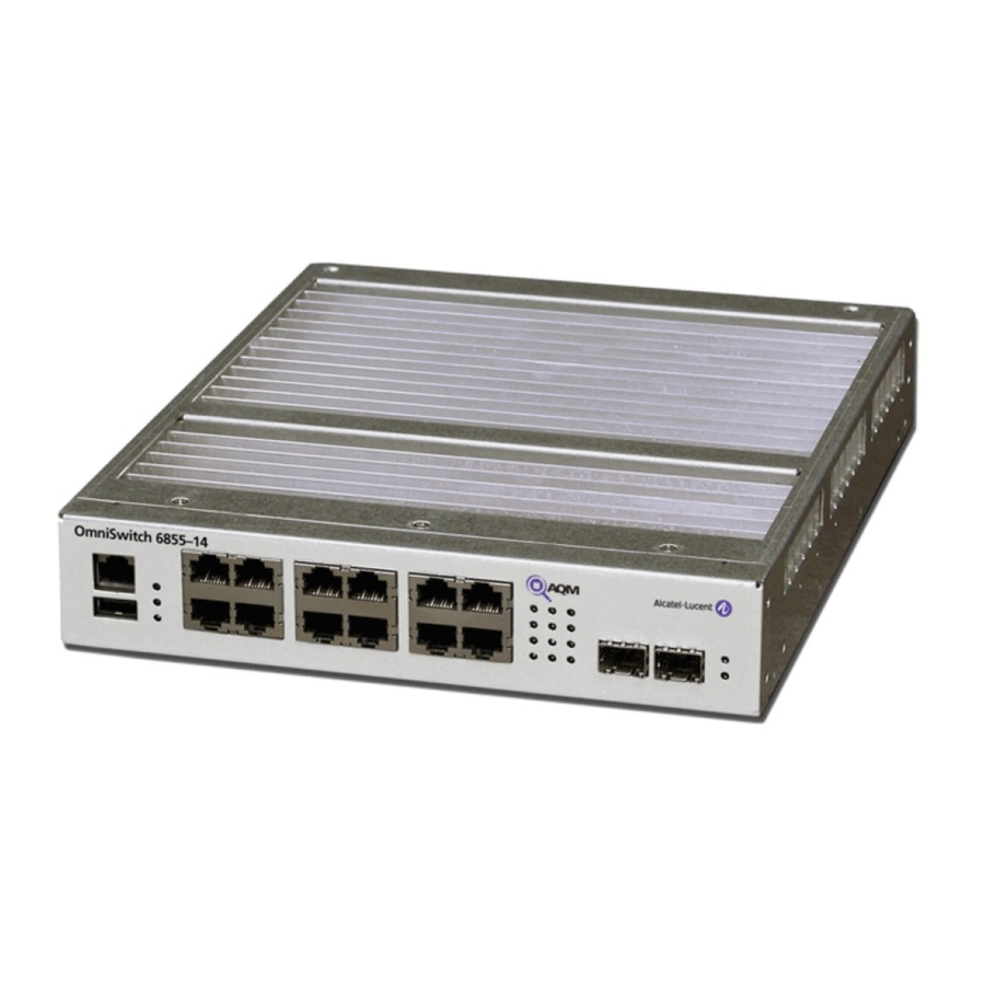
OmniSwitch 6855-14 OmniSwitch 6855 Series Chassis and Hardware Components OmniSwitch 6855-14 The OmniSwitch 6855-C14 is an edge/workgroup switch offering 12 10/100/1000 Base-T, and two SFP connectors. Additionally, the first four ports support PoE. The front panel of the OS6855-14 chassis contains the following major components: System status and slot indicator LEDs •... - Page 33 OmniSwitch 6855 Series Chassis and Hardware Components OmniSwitch 6855-14 Refer to the illustration below for more front panel information. For detailed LED descriptions, refer to page 2-16. For information on the chassis rear panel, refer to page 2-18. Status LEDs For information on the ’s sta- OS6855-14...
- Page 34 OmniSwitch 6855-14 OmniSwitch 6855 Series Chassis and Hardware Components OS6855-14 Specifications Total unshared 10/100/000Base- T per switch (1–12) Total 802.3af PoE ports per switch (1–4) Total shared SFP connectors per switch (13–14) Flash memory size 128 MB RAM memory size 256 MB SDRAM Chassis Width 8.5 inches...
-
Page 35: Omniswitch 6855-U10
OmniSwitch 6855 Series Chassis and Hardware Components OmniSwitch 6855-U10 OmniSwitch 6855-U10 The OmniSwitch 6855-U10 is an edge/workgroup switch offering 8 SFP connectors, and two ports indi- vidually configurable to 10/100/1000Base-T. The front panel of the OS6855-U10 chassis contains the following major components: System status and slot indicator LEDs •... - Page 36 OmniSwitch 6855-U10 OmniSwitch 6855 Series Chassis and Hardware Components Refer to the illustration below for more front panel information. For detailed LED descriptions, refer to page 2-16. For information on the chassis rear panel, refer to page 2-18. Console Port Status LEDs The OS6855-U10 front panel For information on the...
- Page 37 OmniSwitch 6855 Series Chassis and Hardware Components OmniSwitch 6855-U10 OS6855-U10 Specifications Total unshared SFP connectors per switch (1–8) Total unshared 10/100/ 1000Base-T per switch (9–10) Flash memory size 128 MB RAM memory size 256 MB SDRAM Chassis Width 8.5 inches Chassis Height 1.73 inches Chassis Height (rack units)
-
Page 38: Status Leds
Solid green when an PS2. System Status OmniSwitch 6855-24 Console CLASS 1 LASER PRODUCT Ethernet Port LEDs Combo Port Status LEDs Displays solid green when an SFP is installed in 10/100/1000 Ethernet port have one the corresponding port and a link state exists;... - Page 39 OmniSwitch 6855 Series Chassis and Hardware Components Status LEDs State Description Solid Green Normal Operation. Solid Amber Operating Temperature Exceeded. Solid Green PS1 Normal Operation. Amber PS1 Present and Bad (24-port models only) PS1 Not Present or Bad. Solid Green PS2 Normal Operation.
-
Page 40: Rear Panel
Rear Panel OmniSwitch 6855 Series Chassis and Hardware Components Rear Panel OS6855-24/OS6855-U24 The rear panel of OS6855-24/OS6855-U24 switches contains the following major components: Two DB-25 connectors provided for primary and redundant power supplies. • Grounding block for type LCD8-10A-L grounding lug •... -
Page 41: Os6855-14
OmniSwitch 6855 Series Chassis and Hardware Components Rear Panel OS6855-14 The rear panel of OS6855-14 switch contains the following major components: Two 3-pin connectors provided for primary and redundant system power supplies • Two 4-pin connectors provided for primary and redundant PoE power supplies •... -
Page 42: Os6855-U10
Rear Panel OmniSwitch 6855 Series Chassis and Hardware Components OS6855-U10 The rear panel of OS6855-U10 switch contains the following major components: Two multi-contact connectors provided for primary and redundant power supplies. • Grounding block for type LCD8-10A-L grounding lug • Note. -
Page 43: Os6855-24/U24 Power Supplies
OmniSwitch 6855 Series Chassis and Hardware Components OS6855-24/U24 Power Supplies OS6855-24/U24 Power Supplies PS-126I80AC Power Supply (see “PS-126I80AC Power Supply” on page 2-22) • PS-360I160AC-P PoE Power Supply (see “PS-360I160AC-P Power Supply” on page 2-23) • PS-120I80DC48 - 48V DC Power Supply (see “PS-120I80DC48 Power Supply”... -
Page 44: Omniswitch 6855 Series Hardware Users Guide March 2009
OS6855-24/U24 Power Supplies OmniSwitch 6855 Series Chassis and Hardware Components PS-126I80AC Power Supply The PS-126I80AC Power Supply provides full system power for OmniSwitch 6855 Series switches and can be installed as either a primary or backup system power supply. 80W AC Sytem Power Supply P/S Component Description Model... -
Page 45: Ps-360I160Ac-P Power Supply
PS-360I160AC-P Power Supply The PS-360I160AC-P Power Supply provides full system and Power over Ethernet (PoE) for the OmniSwitch 6855-24 and can be installed as either a primary or backup system and PoE power supply. 160W, AC PoE/System Power Supply P/S Component... - Page 46 OS6855-24/U24 Power Supplies OmniSwitch 6855 Series Chassis and Hardware Components page 2-24 OmniSwitch 6855 Series Hardware Users Guide March 2009...
-
Page 47: Ps-120I80Dc48 Power Supply
OmniSwitch 6855 Series Chassis and Hardware Components OS6855-24/U24 Power Supplies PS-120I80DC48 Power Supply The PS-120I80DC48 DC Power Supply provdes full system power for OmniSwitch 6855 Series switches and can be installed as either the primary or backup system power supply. 80W, -48VDC System Power Supply P/S Component Description... -
Page 48: Ps-100I80Dc24 Power Supply
OS6855-24/U24 Power Supplies OmniSwitch 6855 Series Chassis and Hardware Components PS-100I80DC24 Power Supply The PS-100I80DC24 Power Supply provides full system power for OmniSwitch 6855 Series switches and can be installed as either the primary or backup system power supply. 80W, 24VDC System Power Supply P/S Component Description Model... -
Page 49: Os6855-14/U10 Power Supplies
OmniSwitch 6855 Series Chassis and Hardware Components OS6855-14/U10 Power Supplies OS6855-14/U10 Power Supplies PS-I40AC - System Power Brick (see “PS-I40AC Power Brick” on page 2-29) • PS-I66AC-P - PoE Power Brick (see “PS-I66AC-P PoE Power Brick” on page 2-30) • PS-I40DC2448 - DC Power Brick (see “PS-I40DC2448 Power Brick”... - Page 50 OS6855-14/U10 Power Supplies OmniSwitch 6855 Series Chassis and Hardware Components page 2-28 OmniSwitch 6855 Series Hardware Users Guide March 2009...
-
Page 51: Ps-I40Ac Power Brick
OmniSwitch 6855 Series Chassis and Hardware Components OS6855-14/U10 Power Supplies PS-I40AC Power Brick The PS-I40AC Power Brick provides full system power for the OmniSwitch 6855 Series switches and can be installed as either the primary or backup system power supply. 40W, AC System Power Brick P/S Component Description... -
Page 52: Ps-I66Ac-P Poe Power Brick
OS6855-14/U10 Power Supplies OmniSwitch 6855 Series Chassis and Hardware Components PS-I66AC-P PoE Power Brick The PS-I66AC-P PoE Power Brick provides Power over Ethernet for the OmniSwitch 6855-14 and can be installed as either the primary or backup PoE power supply. 66W, AC PoE Power Brick P/S Component Description... -
Page 53: Ps-I40Dc2448 Power Brick
OmniSwitch 6855 Series Chassis and Hardware Components OS6855-14/U10 Power Supplies PS-I40DC2448 Power Brick The PS-I40DC2448 DC Power Brick provides full system power for the OmniSwitch 6855 Series switches and can be installed as either the primary or backup system power supply. 40W, 24/-48VDC System Power Brick P/S Component Description... -
Page 54: Ps-I40Dc2448E Power Brick
OS6855-14/U10 Power Supplies OmniSwitch 6855 Series Chassis and Hardware Components PS-I40DC2448E Power Brick The PS-I40DC2448E DC Power Brick provides full system power for the OmniSwitch 6855 Series switches and can be installed as either the primary or backup system power supply. 40W, 24/-48VDC System Power Brick P/S Component Description... -
Page 55: Ps-75I42Dc48-P Poe Power Brick
OmniSwitch 6855 Series Chassis and Hardware Components OS6855-14/U10 Power Supplies PS-75I42DC48-P PoE Power Brick The PS-75I42DC48-P DC PoE Power Brick provides Power over Ethernet for the OmniSwitch 6855-14 and can be installed as either the primary or backup PoE power supply. 75W, -54.5VDC PoE Power Brick P/S Component Description... -
Page 56: Ul Recognized Power Supply Table
UL Recognized Power Supply Table OmniSwitch 6855 Series Chassis and Hardware Components UL Recognized Power Supply Table POWER SUPPLIES: Only the following UL Recognized Component Power Supplies may be used for OS6855-U10, OS6855- 14, OS6855-24 & OS6855-U24 bearing the UL Listing Mark - Model OS6855 Supply Voltage UL Recognized Component (QQGQ2) Power Supplies AC, DC, PoE... -
Page 57: Power Supply Shelf
UL Recognized Power Supply Table Power Supply Shelf OS6855-24/U24 Alcatel-Lucent requires the use of the power supply shelf when connecting power supplies. The shelf can be attached directly to the back of the chassis or rack mounted. OS6855-24/U24 Power Supply Shelf OS6855-14/U10 Alcatel-Lucent requires the use of the power supply shelf when connecting power supplies. -
Page 58: Ac Power Cords
AC Power Cords OmniSwitch 6855 Series Chassis and Hardware Components AC Power Cords Since the power cord is the switch’s only disconnect device, it should be plugged into an easily accessible outlet. In the event that your power cord is lost or damaged, refer to the specifications below. Specifications The power cord included with this product contains three (3) insulated #18AWG stranded copper wires and is rated between 85-265 VAC (region dependent), 10 amps with a nominal length of 2 meters. -
Page 59: Dc Power Supply Considerations
OmniSwitch 6855 Series Chassis and Hardware Components DC Power Supply Considerations DC Power Supply Considerations In addition to the installation steps described in “Connecting a Power Supply Directly to the Chassis” on page 3-5 “Rack Mounting the Power Supply Tray” on page 3-6 DC power supplies have the follow- ing additional considerations: Connect to a -48V reliably grounded DC SELV source if using either a PS-120I80DC48 or PS-... -
Page 60: Installing Dc Power Source Wire Leads
DC Power Supply Considerations OmniSwitch 6855 Series Chassis and Hardware Components A clamp inside each slot keeps the power wire tightly in place during operation. The DC power supply has side screws that can be used to remove the connector if required. Installing DC Power Source Wire Leads These instructions describe how to connect your 3-wire DC power source to the power connector on your DC power supply. - Page 61 OmniSwitch 6855 Series Chassis and Hardware Components DC Power Supply Considerations Tighten the clamp by tightening the screw above the slot into which you inserted the wire lead. The wire lead should be securely attached inside the connector. You should be able to pull on the wire and not dislodge it.
-
Page 62: Console Port
Console Port OmniSwitch 6855 Series Chassis and Hardware Components Console Port The console port, located on the chassis front panel, provides a console connection to the switch and is required when logging into the switch for the first time. By default, this RJ-45 connector provides a DTE console connection. -
Page 63: Port Pinouts
OmniSwitch 6855 Series Chassis and Hardware Components Port Pinouts Port Pinouts RJ-45 Console Port – Connector Pinout Pin Number Signals as DTE Console Port Ground Ground 10/100 Ethernet Port – RJ-45 Pinout (non-PoE) Pin Number Description not used not used not used not used Gigabit Ethernet Port –... -
Page 64: 10/100/1000 Mbps Power Over Ethernet Port - Rj-45 Pinout
Overtemp Condition OmniSwitch 6855 Series Chassis and Hardware Components 10/100/1000 Mbps Power over Ethernet Port – RJ-45 Pinout Pin Number Description RX+ (-VDC) RX- (-VDC) TX+ (+VDC) TX- (+VDC) Overtemp Condition The OmniSwitch 6855 is designed to operate within a wider operating temperature range than normal network equipment as noted under the specifications section. - Page 65 OmniSwitch 6855 Series Chassis and Hardware Components Overtemp Condition OmniSwitch 6855 Series Hardware Users Guide March 2009 page 2-43...
- Page 66 Overtemp Condition OmniSwitch 6855 Series Chassis and Hardware Components page 2-44 OmniSwitch 6855 Series Hardware Users Guide March 2009...
-
Page 67: Mounting Os6855-24 And Os6855-U24
3 Mounting OS6855-24 and OS6855-U24 Note. Never obstruct the air intake or exhaust vents located on the chassis. Obstructing these vents can cause switch failure. Always follow the recommended clearance values. General Mounting Recommendations Be sure that your switch is placed in a well-ventilated, static-free environment. Always allow adequate clearance at the front, rear, top, and sides of the switch. -
Page 68: Elevated Operating Ambient Temperatures
General Mounting Recommendations Mounting OS6855-24 and OS6855-U24 Elevated Operating Ambient Temperatures If installed in a closed or multi-unit rack assembly, the operating ambient temperature of the rack environ- ment may be greater than room ambient. Therefore, consideration should be given to installing the equip- ment in an environment compatible with the maximum ambient temperature (Tma) specified by the manufacturer. -
Page 69: Airflow Recommendations
Mounting OS6855-24 and OS6855-U24 Airflow Recommendations Airflow Recommendations Air flow for the OS6855-24 switch differs slightly from the air flow for OS6855-U24 switches. The OS6855-24 draws air from intake vents located in the front and right chassis panels and exhausts air via fan vents located in the left chassis panel. -
Page 70: Chassis Airflow For Os6855-U24
Airflow Recommendations Mounting OS6855-24 and OS6855-U24 Chassis Airflow for OS6855-U24 1. Air Intake. The chassis fans pull air from the main air intake vent located at the top-front of the chassis. Air Intake Vent Louvered Exhaust Vents Front of Chassis 3. -
Page 71: Installing Power Supplies
Mounting OS6855-24 and OS6855-U24 Installing Power Supplies Installing Power Supplies OmniSwitch 6855 Series power supply can be installed in the following ways: As a primary or backup supply directly connected to the back of an OmniSwitch 6855 Series chassis. • “Connecting a Power Supply Directly to the Chassis”... -
Page 72: Rack Mounting The Power Supply Tray
Installing Power Supplies Mounting OS6855-24 and OS6855-U24 Carefully slide the power supply against the back of the chassis until the power connector securely connects. Tighten the captive screw for each power supply located at back of the power supply to the power supply tray. - Page 73 Mounting OS6855-24 and OS6855-U24 Installing Power Supplies Carefully slide the power supply on to the power supply tray and secure the power supply to the tray using the captive screws. Tighten these screws to secure the power supply. Attaching a Power Supply to the Power Supply Tray Note.
-
Page 74: Connecting The Power Supply Cable
Installing Power Supplies Mounting OS6855-24 and OS6855-U24 Connecting the Power Supply Cable Follow the steps below to connect a power supply with a cable: Be sure the chassis ( see “Rack-Mounting the Chassis” on page 3-12 ) and power supply tray are securely fastened to the rack. -
Page 75: Securing Power Supply Cord
Mounting OS6855-24 and OS6855-U24 Installing Power Supplies Securing Power Supply Cord The following section describes how to secure the power supply cord to the power supply using the included power supply cord retaining bracket. If necessary, disconnect the AC power cord from the power supply. Remove the screw directly above the AC power supply receptable on the power supply and set aside, this screw will be used to secure the power supply cord retaining bracket. -
Page 76: Hot-Swapping Power Supplies
Hot-Swapping Power Supplies Mounting OS6855-24 and OS6855-U24 Hot-Swapping Power Supplies OmniSwitch 6855 Series switches support hot-swapping of their power supplies. The following sections describe how to hot-swap a power supply either directly connected (i.e., without a cable) or rack-mounted power supply. Warning: Before proceeding, ensure a redundant power supply is connected and operational. -
Page 77: Hot-Swapping A Rack Mounted Power Supply
Mounting OS6855-24 and OS6855-U24 Hot-Swapping Power Supplies Hot-Swapping a Rack Mounted Power Supply Disconnect the power supply to be hot-swapped from its power source. Loosen the power supply cable of the power-supply to be hot-swapped and disconnect from power supply. Loosen the captive screw of the power supply to be hot-swapped. -
Page 78: Rack-Mounting The Chassis
Note. If you are installing the switch in a 23-inch-wide rack, Alcatel-Lucent offers optional 23-inch rack- mounting hardware. For more information, contact your Alcatel-Lucent representative. Alcatel-Lucent does not provide rack-mount screws. Use the screws supplied by the rack vendor. - Page 79 Mounting OS6855-24 and OS6855-U24 Rack-Mounting the Chassis After the rack-mount flanges are secured to the chassis, mark the holes on the rack where the switch is to be installed. Lift and position the switch until the rack-mount flanges are flush with the rack post. Align the holes in the flanges with the rack holes that were marked in step 3.
-
Page 80: Table Mounting The Chassis
Table Mounting the Chassis Mounting OS6855-24 and OS6855-U24 Table Mounting the Chassis OmniSwitch 6855 Series switches can be installed freestanding as a tabletop unit. Note. Be sure that adequate clearance has been provided for chassis airflow and access to the front, back, and sides of the switch. - Page 81 Mounting OS6855-24 and OS6855-U24 Table Mounting the Chassis Mount the switch assembly on the table by inserting attachment screws through the flat portion of the mounting brackets and into the mounting surface. CHASSIS ASSEMBLY TABLE SURFACE OmniSwitch 6855 Series Hardware Users Guide March 2009 page 3-15...
- Page 82 Table Mounting the Chassis Mounting OS6855-24 and OS6855-U24 page 3-16 OmniSwitch 6855 Series Hardware Users Guide March 2009...
-
Page 83: Mounting Os6855-14 And Os6855-U10 Switches
4 Mounting OS6855-14 and OS6855-U10 Switches This chapter covers different mounting and installation options for OS6855-14 and OS6855-U10 switches. Anti-Static Warning. Before handling any components, free yourself of static by wearing a grounding strap, or by grounding yourself properly. Static discharge can damage the switch and the backup power supply. -
Page 84: General Installation Recommendations
General Installation Recommendations Mounting OS6855-14 and OS6855-U10 Switches General Installation Recommendations Cooling Recommendations OS6855-14 and OS6855-U10 switches are convection-cooled using finned heat sinks. Although air flow is not mandatory for switch operation, the best way to ensure proper cooling is to provide some ambient air flow over the heat sinks whenever possible (e.g., from room fans, etc.). -
Page 85: Recommended Clearances
Mounting OS6855-14 and OS6855-U10 Switches General Installation Recommendations Recommended Clearances Always allow adequate clearance at the front, rear, top, and sides of the switch. The following table shows the recommended minimum clearances for adequate chassis cooling and access to cabling and components at the front and rear of the chassis. -
Page 86: Power Supply Information
Power Supply Information Mounting OS6855-14 and OS6855-U10 Switches Power Supply Information Before getting started, please note that OmniSwitch 6855 Series power supplies can be installed in a number of different configurations. For example: Basic single system power, which provides minimum power requirements to the chassis, with no power •... -
Page 87: Rack-Mounting Os6855-14 And Os6855-U10 Switches
• chassis and position it on the rack, and a second person to secure the chassis to the rack using attachment screws. (Please note that Alcatel-Lucent does not provide rack-mount screws. Use the screws supplied by the rack vendor.) To prevent a rack from becoming top heavy, it is recommended that you install heavier equipment at •... - Page 88 Rack-Mounting OS6855-14 and OS6855-U10 Switches Mounting OS6855-14 and OS6855-U10 Switches Attach the S-bracket that was removed at step 1 to the right-rear portion of the power supply tray, as shown. Use the single power supply tray attachment screw (provided). S-bracket Re-attach the S-bracket removed at step one Power supply tray to the power supply tray, as shown.
- Page 89 For OS6855-14 switches using redundant chassis power in addition to PoE, a total of four power supplies are required. For this configuration, plug a second Alcatel-Lucent-provided system power supply into the PS2 port on the rear panel of the chassis.
- Page 90 Rack-Mounting OS6855-14 and OS6855-U10 Switches Mounting OS6855-14 and OS6855-U10 Switches Place the power supply (or supplies) into the power supply tray with the connector cables facing forward. Note. For switches using redundant chassis power with PoE, place the power supplies connected to the PS1 and PoE1 ports side-by-side in the tray.
- Page 91 Mounting OS6855-14 and OS6855-U10 Switches Rack-Mounting OS6855-14 and OS6855-U10 Switches Redundant Chassis Power with PoE (OS6855-14 only) For OS6855-14 switches using redundant chassis power with PoE, an additional power supply tray is required. This power supply tray is included with all shipments for which redundant chassis power and PoE have been specified as requirements.
- Page 92 Rack-Mounting OS6855-14 and OS6855-U10 Switches Mounting OS6855-14 and OS6855-U10 Switches Install one cord retainer bracket to the back of each installed power supply using the attachment screws (provided). Once all retainer clips are attached, place the slotted retainer clip over the bracket with the retainer fingers pointing down and slide the retainer bracket toward the power supply until it meets the power cord connector.
- Page 93 Mounting OS6855-14 and OS6855-U10 Switches Rack-Mounting OS6855-14 and OS6855-U10 Switches Once the holes are aligned, insert a rack mount screw (not provided) through the bottom hole of each flange. Tighten both screws until they are secure. When rack mounting, a clearance of 0.875 inches is recommended above OS6855-14 and OS6855-U10 switches.
-
Page 94: Additional Rack Mounting Options
Rack-Mounting OS6855-14 and OS6855-U10 Switches Mounting OS6855-14 and OS6855-U10 Switches Additional Rack Mounting Options Depending on the number of power supplies, power supply trays, and chassis, the OS6855 can be mounted in a variety of ways as shown below. Redundant System and PoE Power Supplies - Side Mount Redundant System and PoE Power Supplies - Side/Rear Mount page 4-12 OmniSwitch 6855 Series Hardware Users Guide... -
Page 95: General Table-Mounting Guidelines
Mounting OS6855-14 and OS6855-U10 Switches Table-Mounting OS6855-14 and OS6855-U10 Switches Table-Mounting OS6855-14 and OS6855-U10 Switches General Table-Mounting Guidelines OmniSwitch 6855 Series switches can be installed freestanding as tabletop-mounted units. If you will be table-mounting your OS6855-14 and OS6855-U10 switch(es), refer to the important guidelines below before installing. - Page 96 Table-Mounting OS6855-14 and OS6855-U10 Switches Mounting OS6855-14 and OS6855-U10 Switches Next, insert the two tabs at the base of the power supply tray into the slots provided at the bottom-rear portion of the switch chassis. Secure the power supply tray to the rear of the chassis using the attachment screws (provided).
- Page 97 OS6855-14 switches using PoE also require a second power supply. This second power supply is a PoE- specific unit included with your Alcatel-Lucent product shipment. Note. To distinguish PoE power supplies from standard system power supplies, note that PoE supplies have both a long and short connector cable hard-wired into the power supply brick, while standard system power supplies have only a single, long connector cable.
- Page 98 For OS6855-14 switches using redundant chassis power in addition to PoE, a total of four power supplies are required. For this configuration, plug a second Alcatel-Lucent-provided system power supply into the PS2 port on the rear panel of the chassis.
- Page 99 Mounting OS6855-14 and OS6855-U10 Switches Table-Mounting OS6855-14 and OS6855-U10 Switches Plug the power supply cord into the female AC connector located on the back of each power supply brick. Note. For PoE configurations, the system power supplies will already have power cords plugged into the AC connectors.
- Page 100 Table-Mounting OS6855-14 and OS6855-U10 Switches Mounting OS6855-14 and OS6855-U10 Switches Redundant Chassis Power with PoE (OS6855-14 only) If the switch requires both redundant power and PoE, a minimum of four (4) power supplies is required (see page 4-4 for more information). To accommodate four power supplies, a second power supply tray must be installed directly behind the first power supply tray.
- Page 101 Mounting OS6855-14 and OS6855-U10 Switches Table-Mounting OS6855-14 and OS6855-U10 Switches Redundant Chassis Power with PoE (OS6855-14 only) For redundant chassis power with PoE configurations, attach two additional mounting brackets to the rear portion of the second power supply tray. If preferred, mount the complete switch assembly to the table by inserting attachment screws (not provided) through the flat portion of the mounting brackets and into the mounting surface.
-
Page 102: Wall-Mounting Os6855-14 And Os6855-U10 Switches
Wall-Mounting OS6855-14 and OS6855-U10 Switches Mounting OS6855-14 and OS6855-U10 Switches Wall-Mounting OS6855-14 and OS6855-U10 Switches OmniSwitch 6855 Series switches can also be installed as wall-mounted units. General Wall-Mounting Guidelines When choosing a location for the switch, be sure that adequate clearance has been provided for chassis •... -
Page 103: Installation
Mounting OS6855-14 and OS6855-U10 Switches Wall-Mounting OS6855-14 and OS6855-U10 Switches Installation To wall mount the switch, follow steps 1 through 7 in the “Table-Mounting OS6855-14 and OS6855- U10 Switches” section above. Use one person to securely hold the chassis assembly in position on the wall. Mark the location of the holes in the mounting brackets on the wall. -
Page 104: Hot-Swapping Power Supplies
Hot-Swapping Power Supplies Mounting OS6855-14 and OS6855-U10 Switches Hot-Swapping Power Supplies Hot swapping is supported on some OS6855-14 and OS6855-U10 switches. In order to support the hot swapping of power supplies, the switch must have: Redundant system power or redundant PoE power (if hot swapping a PoE supply) •... - Page 105 Mounting OS6855-14 and OS6855-U10 Switches Hot-Swapping Power Supplies Carefully remove the retaining strap from the power supply tray. Be careful not to disrupt the operational power supply adjacent to the power supply being hot swapped. Retaining strap Power supply brick Power supply tray Attachment screw Lift the power supply that is being hot swapped out of the power supply tray and unplug its connector...
- Page 106 Hot-Swapping Power Supplies Mounting OS6855-14 and OS6855-U10 Switches page 4-24 OmniSwitch 6855 Series Hardware Users Guide March 2009...
-
Page 107: Booting 6855 Series Switches
If any of the LED state differs from the states shown in the table above, refer to page 2-7 for more infor- mation. Contact Alcatel-Lucent Customer Support if the LED state persists. For information on logging in and configuring your OmniSwitch 6855 Series switch, refer to the OmniSwitch 6855 Series Getting Started Guide. -
Page 108: Console Port
Console Port Booting 6855 Series Switches Console Port The console port, located on the chassis front panel, provides a console connection to the switch and is required when logging into the switch for the first time. By default, this RJ-45 connector provides a DTE console connection. - Page 109 Booting 6855 Series Switches Console Port To change the stop bits value, enter boot serialstopbits, followed by the number of stop bits. Options include 1 (default) and 2. For example: Boot > boot serialstopbits 2 Verify your current changes by entering show at the boot prompt: Boot >...
-
Page 110: Viewing The Power Supply Status
Console Port Booting 6855 Series Switches Viewing the Power Supply Status The switch constantly monitors the power supply operation. If either the primary or backup power source (optional) unexpectedly shuts down, the switch sends out a notification to the user. In addition, the power LED on the chassis front panel displays solid amber. -
Page 111: Monitoring The Chassis
Booting 6855 Series Switches Monitoring the Chassis Monitoring the Chassis OmniSwitch 6855 Series switches can be monitored and managed via the console port using Command Line Interface (CLI) commands. The switches can also be monitored and managed via the Ethernet using CLI commands, WebView, SNMP, and OmniVista. -
Page 112: Checking The Fan Status
Monitoring the Chassis Booting 6855 Series Switches Checking the Fan Status To check the current status for all six fans in the chassis, use the show fan command. For example: -> show fan Chassis Fan Status -------+---+----------- Running Running Running Running For a complete list of output definitions for this command, refer to the OmniSwitch CLI Reference Guide. -
Page 113: Using Leds To Visually Monitor The Chassis
Booting 6855 Series Switches Monitoring the Chassis Using LEDs to Visually Monitor the Chassis The front panel of OmniSwitch 6855 Series switches provides status LEDs that are useful in visually monitoring the status of standalone switches. Front panel LEDs include: Ethernet Port LEDs •... - Page 114 Monitoring the Chassis Booting 6855 Series Switches page 5-8 OmniSwitch 6855 Series Hardware Users Guide March 2009...
-
Page 115: Installing And Managing Power Over Ethernet (Poe)
OmniSwitch 6850 Series chassis. Important. Alcatel-Lucent recommends that PoE-enabled switches with attached IP telephones should have operational power supply redundancy at all times for 911 emergency requirements. In addition, both the switch and the power supply should be plugged into an Uninterruptible Power Source (UPS). -
Page 116: In This Chapter
Note. You can also monitor all chassis components and manage many chassis features, including Power over Ethernet, with WebView, Alcatel-Lucent’s embedded web-based device management application. WebView is an interactive and easy-to-use GUI that can be launched from the OmniVista or a web browser. -
Page 117: Power Over Ethernet Specifications
Installing and Managing Power over Ethernet (PoE) Power over Ethernet Specifications Power over Ethernet Specifications The table below lists general specifications for Alcatel-Lucent’s Power over Ethernet support. For more detailed power supply and Power Source Equipment (PSE) specifications, refer to Chapter 2, “OmniSwitch 6855 Series Chassis and Hardware Components.”... -
Page 118: Viewing Poe Power Supply Status
Viewing PoE Power Supply Status Installing and Managing Power over Ethernet (PoE) Viewing PoE Power Supply Status To view the current status of power supplies installed, use the show power command, as shown below: -> show power Slot Wattage Type Status Location ----+----+---------+------+-----------+----------... -
Page 119: Configuring Power Over Ethernet Parameters
Installing and Managing Power over Ethernet (PoE) Configuring Power over Ethernet Parameters Configuring Power over Ethernet Parameters Power over Ethernet Defaults The following table lists the defaults for PoE configuration: Parameter Description Command(s) Default Value/Comments PoE operational status lanpower start lanpower stop Disabled Total power allocated to a port... -
Page 120: Configuring The Total Power Allocated To A Port
Configuring Power over Ethernet Parameters Installing and Managing Power over Ethernet (PoE) Disabling PoE To disable PoE on a particular slot or port, use the lanpower stop command. To disable PoE on a specific PoE-capable port, enter a slot/port number. For example: ->... -
Page 121: Setting Port Priority Levels
Installing and Managing Power over Ethernet (PoE) Configuring Power over Ethernet Parameters To increase or decrease the total power allocated to a slot, use the lanpower maxpower command. Since you are setting the power allowance for an individual slot, you must specify a slot number in the command line. -
Page 122: Understanding Priority Disconnect
Understanding Priority Disconnect Installing and Managing Power over Ethernet (PoE) Understanding Priority Disconnect The priority disconnect function differs from the port priority function described on page 6-7 in that it applies only to the addition of powered devices (PDs) in tight power budget conditions. Priority discon- nect is used by the system software in determining whether an incoming PD will be granted or denied power when there are too few watts remaining in the PoE power budget for an additional device. -
Page 123: Priority Disconnect Is Enabled; Same Priority Level On All Pd
Installing and Managing Power over Ethernet (PoE) Understanding Priority Disconnect Priority Disconnect is Enabled; Same Priority Level on All PD Reminder. Priority disconnect examples are applicable only when there is inadequate power remaining to power an incoming device. When a PD is being connected to a port with the same priority level as all other in the slot, the physical port number is used to determine whether the incoming PD will be granted or denied power. -
Page 124: Priority Disconnect Is Disabled
Understanding Priority Disconnect Installing and Managing Power over Ethernet (PoE) Priority Disconnect is Disabled Reminder. Priority disconnect examples are applicable only when there is inadequate power remaining to power an incoming device. When priority disconnect is disabled, power will be denied to any incoming PD, regardless of its port priority status (i.e., low, high, and critical) or physical port number (i.e., 1/1). -
Page 125: Monitoring Power Over Ethernet Via Cli
Installing and Managing Power over Ethernet (PoE) Monitoring Power over Ethernet via CLI Monitoring Power over Ethernet via CLI To monitor current PoE statistics and settings, use the show lanpower command. The command output displays a list of all current PoE-capable, along with the following information for each port: Maximum power allocated to the port, in milliwatts •... - Page 126 Monitoring Power over Ethernet via CLI Installing and Managing Power over Ethernet (PoE) page 6-12 OmniSwitch 6855 Series Hardware Users Guide March 2009...
-
Page 127: Regulatory Compliance And Safety Information
A Regulatory Compliance and Safety Information This appendix provides information on regulatory agency compliance and safety for the OmniSwitch 6855 Series switches. Declaration of Conformity: CE Mark This equipment is in compliance with the essential requirements and other provisions of Directive 73/23/EEC and 89/336/EEC as amended by Directive 93/68/EEC. -
Page 128: China Rohs: Hazardous Substance Table
对销售之日的所售产品,本表显示, 阿尔卡特朗讯公司供应链的电子信息产品可能包含这些物质。注意:在所售产 品中可能会也可能不会含有所有所列的部件。 This table shows where these substances may be found in the supply chain of Alcatel-Lucent electronic information products, as of the date of sale of the enclosed product. Note that some of the component types listed above may or may not be a part of the enclosed product. - Page 129 Regulatory Compliance and Safety Information China RoHS: Hazardous Substance Table Products are packaged using one or more of the following packaging materials: Corrugated Cardboard Corrugated Fiberboard Low-Density Polyethylene OmniSwitch 6855 Series Hardware Users Guide March 2009 page A-3...
-
Page 130: Waste Electrical And Electronic Equipment (Weee) Statement
Waste Electrical and Electronic Equipment (WEEE) Statement Regulatory Compliance and Safety Information Waste Electrical and Electronic Equipment (WEEE) Statement The product at end of life is subject to separate collection and treatment in the EU Member States, Norway and Switzerland and therefore marked with the symbol: Treatment applied at end of life of the product in these countries shall comply with the applicable national laws implementing directive 2002/96EC on waste electrical and electronic equipment (WEEE). -
Page 131: Standards Compliance
Regulatory Compliance and Safety Information Standards Compliance Standards Compliance Safety Agency Certifications US UL 60950 • IEC 60950-1:2001; all national deviations • EN 60950-1: 2001; all deviations • CAN/CSA-C22.2 No. 60950-1-03 • NOM-019 SCFI, Mexico • AS/NZ TS-001 and 60950:2000, Australia •... -
Page 132: Ets
Standards Compliance Regulatory Compliance and Safety Information EN 61000-6-4 • EN 61000-4-11 • ETS 300 019 Storage Class 1.1 • ETS 300 019 Transportation Class 2.3 • ETS 300 019 Stationary Use Class 3.1 • FCC Class A and B, Part 15 This equipment has been tested and found to comply with the limits for Class A and B digital device pursuant to Part 15 of the FCC Rules.These limits are designed to provide reasonable protection against harmful interference when the equipment is operated in a commercial environment.This equipment gener-... -
Page 133: Jate
Regulatory Compliance and Safety Information Standards Compliance JATE This equipment meets the requirements of the Japan Approvals Institute of Telecommunications Equip- ment (JATE). CISPR22 Class A warning This is a Class A product. In a domestic environment, this product may cause radio interference. Under such circumstances, the user may be requested to take appropriate countermeasures. -
Page 134: Commerical
Standards Compliance Regulatory Compliance and Safety Information Use Panduit Corporation, P/N: CT-940CH for crimping. (Each Module must have its own grounding conductor.) (GR-1089 requires treatment of ground connections and painted surfaces as needed during installation.) All surfaces that are used for intentionally grounding the EUT shall be brought to a bright finish and an anti oxidant solution must be applied to the surfaces being joined. - Page 135 Regulatory Compliance and Safety Information Standards Compliance Environmental Testing: MIL-STD-810F, Methods 500/501/502/503/504/505/506/507/508/509/510/ • 512/ 514/515/516/520/521 Low Pressure, Low Temperature, High Temperature, Temperature Shock, • Solar Radiation, Rain, Humidity, Fungus, Salt Fog, Sand and Dust, Immersion, Acoustic Noise, • Icing/Freezing Rain •...
-
Page 136: Translated Safety Warnings
Translated Safety Warnings Regulatory Compliance and Safety Information Translated Safety Warnings Chassis Lifting Warning Two people are required when lifting the chassis. Due to its weight, lifting the chassis unassisted can cause personal injury. Also be sure to bend your knees and keep your back straight when assisting with the lift- ing of the chassis. -
Page 137: Installation Warning
Regulatory Compliance and Safety Information Translated Safety Warnings Installation Warning Only personnel knowledgeable in basic electrical and mechanical procedures should install or maintain this equipment. Français: Toute installation ou remplacement de l'appareil doit être réalisée par du personnel qualifié et compétent. -
Page 138: Lithium Battery Warning
Español: Si substituye las pilas de litio en su chasis, siempre utilice el mismo modelo o el tipo equiva- lente de pila recomendada por el fabricante. Deshágase de las pilas usadas según las instrucciones del fabricante. Devuelva el módulo con la pila de litio a Alcatel-Lucent. La pila de litio será substituida en la fábrica de Alcatel-Lucent. -
Page 139: Power Disconnection Warning
Regulatory Compliance and Safety Information Translated Safety Warnings Power Disconnection Warning Your switch is equipped with multiple power supplies. To reduce the risk of electrical shock, be sure to disconnect all power connections before servicing or moving the unit. Français: Il se peut que cette unité soit équipée de plusieurs raccordements d'alimentation. Pour supprimer tout courant électrique de l'unité, tous les cordons d'alimentation doivent être débranchés. -
Page 140: Read Important Safety Information Warning
Translated Safety Warnings Regulatory Compliance and Safety Information Read Important Safety Information Warning The Getting Started Guide that accompanied this equipment contains important safety information about which you should be aware when working with hardware components in this system. You should read this guide before installing, using, or servicing this equipment. -
Page 141: Wrist Strap Warning
Français: L'électricité statique (ESD) peut endommager les composants du commutateur. Pour cette raison Alcatel-Lucent joint à l'envoi du châssis un bracelet antistatique à brancher sur la prise mise à la terre située en bas à droite du commutateur. Vous devrez mettre ce bracelet avant toute intervention hard- ware. -
Page 142: Instrucciones De Seguridad En Español
Deseche las baterías usadas según las instrucciones del fabricante. Las instrucciones del fabricante son como sigue: Devuelva el módulo con la batería del litio a Alcatel-Lucent. La batería del litio será substitu- ida en la fábrica de Alcatel-Lucent. -
Page 143: Advertencia Sobre Una Apropiada Conexión A Tierra
Regulatory Compliance and Safety Information Instrucciones de seguridad en español Advertencia sobre una apropiada conexión a tierra Para evitar peligro de descargas: El cable de alimentación debe estar conectado a una toma de alimentación adecuadamente cableada • y con toma de tierra. Cualquier equipo al cual se conecte este producto debe estar también conectado a tomas de alimentación adecuadamente cableadas. - Page 144 Instrucciones de seguridad en español Regulatory Compliance and Safety Information page A-18 OmniSwitch 6855 Series Hardware Users Guide March 2009...
-
Page 145: Index
OS6855-24 front panel OmniSwitch 6855-U24 2-10 OS6855-U10 front panel 2-13 technical specifications OS6855-U24 front panel 2-7, 2-10 OS6855-24 rear panel 2-18 see OmniSwitch 6855-24 chassis types OS6855-U10 OS6855-24 see OmniSwitch 6855-U10 OS6855-U10 2-13 OS6855-U24 OS6855-U24 2-7, 2-10 see OmniSwitch 6855-U24... - Page 146 2-36 status LEDs 2-16 Status LED Table 2-17 Status LEDs 2-16 technical specifications console port 2-40, 2-41, 5-2 OmniSwitch 6855-14 2-12 OmniSwitch 6855-24 OmniSwitch 6855-U10 2-15 OmniSwitch 6855-U24 pinouts 2-41 Index-2 OmniSwitch 6855 Series Hardware Users Guide March 2009...
Need help?
Do you have a question about the OmniSwitch 6855-24 and is the answer not in the manual?
Questions and answers