Alcatel-Lucent OmniSwitch 6450 User Manual
Hide thumbs
Also See for OmniSwitch 6450:
- Management manual (366 pages) ,
- Getting started manual (22 pages) ,
- Hardware user's manual (158 pages)

Related Manuals for Alcatel-Lucent OmniSwitch 6450


Summary of Contents for Alcatel-Lucent OmniSwitch 6450
-
Page 1: Users Guide
Part No. 060351-10, Rev. C July 2012 OmniSwitch 6450 Hardware Users Guide www.alcatel-lucent.com... - Page 2 This user guide documents OmniSwitch 6450 hardware, including chassis and associated components. The specifications described in this guide are subject to change without notice. Copyright © 2012 by Alcatel-Lucent. All rights reserved. This document may not be reproduced in whole or in part without the express written permission of Alcatel-Lucent.
-
Page 3: Table Of Contents
........2-1 OmniSwitch 6450-10 ......................2-2 Major Components ....................2-2 Front Panel .......................2-2 OmniSwitch 6450-10 Rear Panel ................2-3 OmniSwitch 6450-10 Internal AC Power Supply ............2-3 OmniSwitch 6450-P10 ....................2-5 Major Components ....................2-5 Front Panel .......................2-5 OmniSwitch 6450-P10 Rear Panel ................2-6 OmniSwitch 6450-P10 Internal AC Power Supply ..........2-6 OmniSwitch 6450-24 ......................2-8... - Page 4 Contents Major Components ....................2-8 Front Panel .......................2-8 OmniSwitch 6450-24 Rear Panel ................2-9 OmniSwitch 6450-24 Internal AC Power Supply ............2-9 OmniSwitch 6450-P24 ....................2-11 Major Components ....................2-11 Front Panel ......................2-11 OmniSwitch 6450-P24 Rear Panel .................2-12 OmniSwitch 6450-P24 Internal AC Power Supply ..........2-12 OmniSwitch 6450-48 ....................2-14...
- Page 5 Additional Monitoring Commands ................4-5 Using LEDs to Visually Monitor the Chassis ............4-5 Chapter 5 Managing Power over Ethernet (PoE) ..............5-1 In This Chapter ........................5-2 Power over Ethernet Specifications ................5-3 Viewing PoE Power Supply Status .................5-4 OmniSwitch 6450 Hardware Users Guide July 2012...
- Page 6 Monitoring Power over Ethernet via CLI ..............5-10 Chapter 6 Managing OmniSwitch 6450 Stacks ..............6-1 In This Chapter ........................6-1 OmniSwitch 6450 Stacking Specifications ..............6-2 OmniSwitch 6450 Stack Overview .................6-2 Expansion Modules and Stacking Mode Detection ............6-3 Swapping Expansion Modules .................6-3 Roles Within the Stack ....................6-4 Primary and Secondary Management Modules ............6-4...
- Page 7 Advertencia sobre la tensión de operación ............A-13 Advertencia sobre la desconexión de la fuente ............. A-13 Advertencia sobre una apropiada conexión a tierra ..........A-14 Leer “información importante de seguridad” ............A-14 OmniSwitch 6450 Hardware Users Guide July 2012...
- Page 8 Contents Advertencia de acceso restringido ................. A-14 Advertencia de pulsera antiestática ............... A-14 Clase de seguridad ....................A-14 viii OmniSwitch 6450 Hardware Users Guide July 2012...
-
Page 9: About This Guide
About This Guide This OmniSwitch 6450 Hardware Users Guide describes your switch hardware components and basic switch hardware procedures. Supported Platforms The information in this guide applies to the following products: • OmniSwitch 6450-10 (L) • OmniSwitch 6450-P10 (L) •... -
Page 10: Who Should Read This Manual
CLI commands that pertain directly to hardware configuration, but it is not intended as a software users guide. There are several OmniSwitch 6450 users guides that focus on switch software configuration. Consult those guides for detailed information and examples for configuring your switch software to operate in a live network environment. -
Page 11: How Is The Information Organized
How is the Information Organized? This users guide provides an overview of OmniSwitch 6450 switches, specifications of the hardware components, steps for setting up and managing OmniSwitch 6450 switches, and an overview and proce- dures for managing Power over Ethernet (PoE). - Page 12 CLI-to-MIB variable mapping information for all CLI commands supported by the switch. This guide can be consulted anytime during the configuration process to find detailed and specific information on each CLI command. page xii OmniSwitch 6450 Hardware Users Guide July 2012...
-
Page 13: Related Documentation
About This Guide Related Documentation Related Documentation The following are the titles and descriptions of OmniSwitch 6450-related user manuals: • OmniSwitch 6450 Getting Started Guide Describes the hardware and software procedures for getting an OmniSwitch up and running. Also provides information on fundamental aspects of OmniSwitch software. -
Page 14: Published / Latest Product Documentation
About This Guide Published / Latest Product Documentation All user guides for the OmniSwitch Series are included on the Alcatel-Lucent public website. This website also includes user guides for other Alcatel-Lucent Enterprise products. The latest user guides can be found on our website at: http://enterprise.alcatel-lucent.com/?dept=UserGuides&page=Portal... -
Page 15: Omniswitch 6450 Switches
Alcatel-Lucent OmniSwitch 6450 Stackable Gigabit Ethernet LAN switches include 10-port, 24-port and 48-port models. OmniSwitch 6450-10 offer Fast and Gigabit Ethernet for classroom, workgroup and small enterprise applications and provide low-power consumption and fanless operation. OmniSwitch 6450-24 and OmniSwitch 6450-48 fixed configuration gigabit switches offer optional upgrade paths for 10 Gigabit Ethernet (GigE) stacking, 10 GigE uplinks and metro Ethernet services. -
Page 16: Chassis Configurations
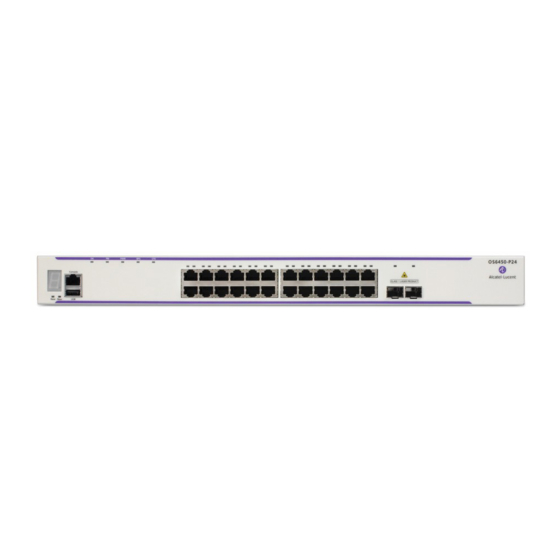
24-Port Models • OmniSwitch 6450-24: Provides 24 10/100/1000 BaseT ports, 2 fixed SFP+ ports and one expansion slot for optional stacking or uplink modules. The chassis features fanless design and internal AC power with optional internal AC or DC backup power. -
Page 17: Combo Ports
The non-combo SFP ports provide uplink capability through the use of supported SFP transceivers. OmniSwitch 6450 Feature Overview Security Features OmniSwitch 6450 switches offer extensive security features for network access control, policy enforcement and attack containment, enabling fully secure networks and OmniVista Network Management System (NMS) support. -
Page 18: Hot Swapping
LEDs, which provide visual status information, are provided on the chassis front panel. LEDs are used to indicate conditions such as hardware and software status, temperature errors, link integrity, data flow, etc. For detailed LED descriptions, refer to Chapter 2, “OmniSwitch 6450 Chassis and Hardware Components.” User-Driven Monitoring User-driven hardware monitoring refers to CLI commands that are entered by the user in order to access the current status of hardware components. -
Page 19: Chapter 2 Omniswitch 6450 Chassis And Hardware Components
2 OmniSwitch 6450 Chassis and Hardware Components OmniSwitch 6450 switches are available in the chassis configurations as shown in the table below: OmniSwitch 6450-10(L) Ten port 10/100/1000BaseT model. Available in 10/100 “L” model. (OS6450-10/OS6450-10L) OmniSwitch 6450-P10(L) Ten port 10/100/1000BaseT Power Over Ethernet model. Available in (OS6450-P10/OS6450- 10/100 “L”... -
Page 20: Omniswitch 6450-10
When pushed, all LEDs will turn off and the LED of the Stack ID will remain lit. (Applies to 24- and 48-port switches.) Refer to “OmniSwitch 6450 LED Status” on page 2-23 for LED status information. page 2-2 OmniSwitch 6450 Hardware Users Guide... -
Page 21: Omniswitch 6450-10 Rear Panel
OmniSwitch 6450 Chassis and Hardware Components OmniSwitch 6450-10 OmniSwitch 6450-10 Rear Panel Note. The figure shows a pre-production version of the chassis without product, safety, and compliance information labels. All production versions of the chassis have these labels. OmniSwitch 6450-10 Rear Panel... - Page 22 OmniSwitch 6450-10 OmniSwitch 6450 Chassis and Hardware Components OS6450-10 Specifications 10/100/1000BaseT ports Total combo ports SFP uplink ports 802.3at PoE ports Flash memory size 128 MB RAM memory size 256 MB SDRAM Chassis Width 8.50 inches (21.5 cm) Chassis Height 1.73 inches (4.40 cm)
-
Page 23: Omniswitch 6450-P10
When pushed, all LEDs will turn off and the LED of the Stack ID will remain lit. (Not currently supported. Functionality scheduled for future release.) Refer to “OmniSwitch 6450 LED Status” on page 2-23 for LED status information. OmniSwitch 6450 Hardware Users Guide... -
Page 24: Omniswitch 6450-P10 Rear Panel
OmniSwitch 6450-P10 OmniSwitch 6450 Chassis and Hardware Components OmniSwitch 6450-P10 Rear Panel Note. The figure shows a pre-production version of the chassis without product, safety, and compliance information labels. All production versions of the chassis have these labels. OmniSwitch 6450-P10 Rear Panel... - Page 25 OmniSwitch 6450 Chassis and Hardware Components OmniSwitch 6450-P10 OS6450-P10 Specifications Total non-combo 10/100/ 8 (1-8) 1000BaseT PoE ports per switch Total combo ports per switch 2 (9-10) Total non-combo SFP ports per 2 (11-12 in Uplink mode) switch Flash memory size...
-
Page 26: Omniswitch 6450-24
Displays link status for expansion module ports. USB Port High speed USB 2.0 port. SFP/SFP+ Ports Two SFP/SFP+ ports to be used for uplinks. Refer to “OmniSwitch 6450 LED Status” on page 2-23 for LED status information. page 2-8 OmniSwitch 6450 Hardware Users Guide July 2012... -
Page 27: Omniswitch 6450-24 Rear Panel
OmniSwitch 6450 Chassis and Hardware Components OmniSwitch 6450-24 OmniSwitch 6450-24 Rear Panel Note. The figure shows a pre-production version of the chassis without product, safety, and compliance information labels. All production versions of the chassis have these labels. OmniSwitch 6450-24 Rear Panel... - Page 28 OmniSwitch 6450-24 OmniSwitch 6450 Chassis and Hardware Components OS6450-24 Specifications RJ-45 10/100/1000BaseT ports SFP+ Gigabit/10Gigabit uplink ports Ports per expansion module Max. chassis per stack Flash memory size 128 MB RAM memory size 256 MB SDRAM Chassis Width 17.32 inches (44.00 cm) Chassis Height 1.73 inches (4.40 cm)
-
Page 29: Omniswitch 6450-P24
Displays link status for expansion module ports. USB Port High speed USB 2.0 port. SFP/SFP+ Ports Two SFP/SFP+ ports to be used for uplinks. Refer to “OmniSwitch 6450 LED Status” on page 2-23 for LED status information. OmniSwitch 6450 Hardware Users Guide July 2012 page 2-11... -
Page 30: Omniswitch 6450-P24 Rear Panel
OmniSwitch 6450-P24 OmniSwitch 6450 Chassis and Hardware Components OmniSwitch 6450-P24 Rear Panel Note. The figure shows a pre-production version of the chassis without product, safety, and compliance information labels. All production versions of the chassis have these labels. OmniSwitch 6450-P24 Rear Panel... - Page 31 OmniSwitch 6450 Chassis and Hardware Components OmniSwitch 6450-P24 OS6450-P24 Specifications RJ-45 10/100/1000BaseT 802.3at PoE ports SFP+ Gigabit/10Gigabit uplink ports Ports per expansion module Max. chassis per stack Flash memory size 128 MB RAM memory size 256 MB SDRAM Chassis Width 17.32 inches (44.00 cm)
-
Page 32: Omniswitch 6450-48
Displays link status for expansion module ports. USB Port High speed USB 2.0 port. SFP/SFP+ Ports Two SFP/SFP+ ports to be used for uplinks. Refer to “OmniSwitch 6450 LED Status” on page 2-23 for LED status information. page 2-14 OmniSwitch 6450 Hardware Users Guide July 2012... -
Page 33: Omniswitch 6450-48 Rear Panel
OmniSwitch 6450 Chassis and Hardware Components OmniSwitch 6450-48 OmniSwitch 6450-48 Rear Panel Note. The figure shows a pre-production version of the chassis without product, safety, and compliance information labels. All production versions of the chassis have these labels. OmniSwitch 6450-48 Rear Panel... - Page 34 OmniSwitch 6450-48 OmniSwitch 6450 Chassis and Hardware Components OS6450-48 Specifications Total non-combo 10/100/ 1000BaseT ports per switch Total non-combo SFP/SFP+ ports per switch Total expansion modules per switch Flash memory size 128 MB RAM memory size 256 MB SDRAM Chassis Width 17.32 inches (44.00 cm)
-
Page 35: Omniswitch 6450-P48
Displays link status for expansion module ports. USB Port High speed USB 2.0 port. SFP/SFP+ Ports Two SFP/SFP+ ports to be used for uplinks. Refer to “OmniSwitch 6450 LED Status” on page 2-23 for LED status information. OmniSwitch 6450 Hardware Users Guide July 2012 page 2-17... -
Page 36: Omniswitch 6450-P48 Rear Panel
OmniSwitch 6450-P48 OmniSwitch 6450 Chassis and Hardware Components OmniSwitch 6450-P48 Rear Panel Note. The figure shows a pre-production version of the chassis without product, safety, and compliance information labels. All production versions of the chassis have these labels. OmniSwitch 6450-P48 Rear Panel... - Page 37 OmniSwitch 6450 Chassis and Hardware Components OmniSwitch 6450-P48 OS6450-P48 Specifications Total non-combo 10/100/ 1000BaseT 802.3at PoE ports per switch Total non-combo SFP/SFP+ ports per switch Total expansion modules per switch Flash memory size 128 MB RAM memory size 256 MB SDRAM Chassis Width 17.32 inches (44.00 cm)
-
Page 38: Omniswitch 6450-U24
Displays link status for expansion module ports. USB Port High speed USB 2.0 port. SFP/SFP+ Ports Two SFP/SFP+ ports to be used for uplinks. Refer to “OmniSwitch 6450 LED Status” on page 2-23 for LED status information. page 2-20 OmniSwitch 6450 Hardware Users Guide July 2012... -
Page 39: Omniswitch 6450-U24 Rear Panel
OmniSwitch 6450 Chassis and Hardware Components OmniSwitch 6450-U24 OmniSwitch 6450-U24 Rear Panel Note. The figure shows a pre-production version of the chassis without product, safety, and compliance information labels. All production versions of the chassis have these labels. OmniSwitch 6450-U24 Rear Panel... - Page 40 OmniSwitch 6450-U24 OmniSwitch 6450 Chassis and Hardware Components OS6450-U24 Specifications Total non-combo SFP ports per switch Total RJ45/SFP combo ports per switch Total non-combo SFP/SFP+ ports per switch Total expansion modules per switch Flash memory size 128 MB RAM memory size...
-
Page 41: Omniswitch 6450 Led Status
OmniSwitch 6450 Chassis and Hardware Components OmniSwitch 6450 LED Status OmniSwitch 6450 LED Status State Description Solid Green The switch has passed hardware diagnostic tests and the system software is operational Blinking Green Normal diagnostics and/or Remote Config Load in progress... -
Page 42: Expansion Modules
Expansion Modules OmniSwitch 6450 Chassis and Hardware Components Expansion Modules OS6450-GNI-C2 The OS6450-GNI-C2 is an optional uplink module that supports two RJ45 Gigabit ports. The module inserts into the expansion slot at the rear of 24- and 48-port OS6450 switches,... -
Page 43: Os6450-Xni-U2
OmniSwitch 6450 Chassis and Hardware Components Expansion Modules OS6450-XNI-U2 The OS6450-XNI-U2 is an optional 10 Gigabit stacking module that supports two SFP+ 10 Gigabit ports. The module inserts into the expansion slot at the rear of 24- and 48-port OS6450 switches. -
Page 44: Omniswitch 6450 Internal Backup Power Supplies
Model PS-90W-DC (Marketing Number OS6450-BP-D) Installation Inserts into backup power supply bay at rear of chassis Provides DC power for one non-PoE switch (OmniSwitch 6450-24, OmniSwitch 6450-48 or OmniSwitch 6450-U24) VDC Range -48 to -60 VDC, maximum Output Rating 12V 11.40V to12.60V 0A 7.5 A 7.5 A A 90 W... -
Page 45: Omniswitch 6450 External Backup Power Supplies
PS-550W-AC-P External 550W AC PoE Power Supply P/S Component Description Model PS-550W-AC-P (Marketing Number OS6450-BP-PH) Platform(s) Supported OmniSwitch 6450-P24 backup power for system and PoE Installation Rack mounts above or below chassis for a 2RU configuration Maximum Output Power 550W (390W for PoE) Input Voltage Range... -
Page 46: Ac Power Cords
AC Power Cords OmniSwitch 6450 Chassis and Hardware Components AC Power Cords Since the power cord is the switch’s only disconnect device, it should be plugged into an easily accessible outlet. In the event that your power cord is lost or damaged, refer to the specifications below. -
Page 47: Console Port
OmniSwitch 6450 Chassis and Hardware Components Console Port Console Port The console port, located on the chassis front panel, provides a console connection to the switch and is required when logging into the switch for the first time. By default, this RJ-45 connector provides a DTE console connection. -
Page 48: Port Pinouts
Port Pinouts OmniSwitch 6450 Chassis and Hardware Components Port Pinouts RJ-45 Console Port – Connector Pinout Pin Number Signals as DTE Console Port Ground Ground 10/100 Ethernet Port – RJ-45 Pinout (non-PoE) Pin Number Description not used not used not used not used Gigabit Ethernet Port –... -
Page 49: 10/100/1000 Mbps Power Over Ethernet Port - Rj-45 Pinout
OmniSwitch 6450 Chassis and Hardware Components Overtemp Condition 10/100/1000 Mbps Power over Ethernet Port – RJ-45 Pinout Pin Number Description RX+ (-VDC) RX- (-VDC) TX+ (+VDC) TX- (+VDC) Overtemp Condition The OmniSwitch is designed to operate within a specified operating temperature as noted under the specifications section. -
Page 50: Dying Gasp
Dying Gasp OmniSwitch 6450 Chassis and Hardware Components Dying Gasp If the switch loses all power it will maintain power long enough to send a Dying Gasp message before completely shutting down. An SNMP trap, Syslog message and Link OAM PDUs will be generated. -
Page 51: Link Oam Pdu
OmniSwitch 6450 Chassis and Hardware Components Dying Gasp Link OAM PDU As soon as the power failure is detected an 802.3ah OAM Information PDU is sent to all ports for which link OAM is enabled and the LinkOAM port status is operational. The PDU will have the Dying Gasp bit set. - Page 52 Dying Gasp OmniSwitch 6450 Chassis and Hardware Components page 2-34 OmniSwitch 6450 Hardware Users Guide July 2012...
-
Page 53: Mounting Omniswitch 6450 Switches
3 Mounting OmniSwitch 6450 Switches This chapter covers different mounting and installation options. OmniSwitch 6450 switches may be either table- or rack-mounted. 24- and 48-port OmniSwitch 6450 switches are rack mounted using factory- installed rack mount flanges. 10-port (1/2 width) switches may be rack mounted using available rack mounting kits. -
Page 54: General Installation Recommendations
6 inches minimum at rear of chassis. 2 inches minimum at left and right sides. 6 inches minimum at front of chassis. 24- and 48-Port Chassis Types page 3-2 OmniSwitch 6450 Hardware Users Guide July 2012... - Page 55 If installed in a closed or multi-unit rack assembly, the operating ambient temperature of the rack environment may be greater than room ambient. Therefore, consideration should be given to installing the equipment in an environment compatible with the maximum ambient temperature (Tma) specified by the manufacturer. OmniSwitch 6450 Hardware Users Guide July 2012 page 3-3...
-
Page 56: Mechanical Loading
(e.g. use of power strips). Table-Mounting OS6450 Switches General Table-Mounting Guidelines OmniSwitch 6450 switches can be installed freestanding as tabletop-mounted units. If you will be table- mounting your switch(es), refer to the important guidelines below before installing. •... -
Page 57: Rack-Mounting 10-Port Os6450 Switches
Rack-Mounting 10-Port OS6450 Switches Rack-Mounting 10-Port OS6450 Switches The following kits are available for rack mounting 10-port (1/2 width) OmniSwitch 6450 switches. Note. Some factory-installed screws may need to be removed prior to mounting, depending on the kit being used. -
Page 58: Installing Available Rack Mounting Kits
No minimum clearance is required below the chassis assembly. However, be sure that the bottom of the chassis is not in direct contact with any equipment below. Rack-mounting Single Chassis page 3-6 OmniSwitch 6450 Hardware Users Guide July 2012... -
Page 59: Installing The Os6450-Dual-Mnt Rack Mount Kit
Fully Assembled Side-by-Side Chassis Assembly Attach the slot-brackets and slide-brackets to the front and back of the chassis using the attachment screws (M3 flat head) provided for each bracket. Attach Slot/Slide-Brackets OmniSwitch 6450 Hardware Users Guide July 2012 page 3-7... - Page 60 Attach rack mount brackets to both sides of the front of the chassis. Attach Rack Mount Brackets Using one additional person, lift and position the assembly on the rack until the rack-mount flanges are flush with the rack post. page 3-8 OmniSwitch 6450 Hardware Users Guide July 2012...
- Page 61 No minimum clearance is required below the chassis assembly. However, be sure that the bottom of the chassis is not in direct contact with any equipment below. Rack-mounting Two Chassis OmniSwitch 6450 Hardware Users Guide July 2012 page 3-9...
-
Page 62: Rack-Mounting 24 And 48-Port Os6450 Switches
10-Port OS6450 Switches” on page 3-5. Refer to the important guidelines below before installing the OmniSwitch 6450 chassis on a rack. Note. When rack mounting multiple switches in a stacked configuration, be sure to place all switches in vertically-adjacent rack positions. This will ensure that all required stacking cables will have adequate length for the installation. -
Page 63: Rack Mounting Steps
Note. Be sure to install the screws in the bottom hole of each flange, as shown, before proceeding. Once the screws at the bottom of each flange are secure, install the remaining two rack mount screws. Be sure that all screws are securely tightened. OmniSwitch 6450 Hardware Users Guide July 2012 page 3-11... -
Page 64: Installing External Poe Power Supplies
Installing External PoE Power Supplies Mounting OmniSwitch 6450 Switches Installing External PoE Power Supplies The following external power supplies provided PoE and backup system power for OmniSwitch 6450 PoE-ready switches: • PS-550W-AC-P (OS6450-P24) • PS-900AC-P (OS6450-P48) These power supplies may be rack mounted above or below the chassis for a 2RU configuration. The following sections describe how to rack-mount a power supply shelf and connect the power supply to the chassis with a cable. -
Page 65: Connecting The Power Supply Cable
Connect the other end of the power supply cable to the power supply and securely tighten. Chassis Connector Power Supply Connector Connect the power cord to the power supply. OmniSwitch 6450 Hardware Users Guide July 2012 page 3-13... -
Page 66: Dc Power Supply Considerations
Follow the steps below to power on the chassis using and AC power source: Connect the IEC-60320-C15 end of the supplied power cord to the chassis. Connect power supply to AC power source. Monitor the chassis as it boots. page 3-14 OmniSwitch 6450 Hardware Users Guide July 2012... - Page 67 If any of the LED state differs from the states shown in the table above, refer to page 2-5 for more information. Contact Alcatel-Lucent Customer Support if the LED state persists. For information on logging in and configuring your switch, refer to the Getting Started Guide. OmniSwitch 6450 Hardware Users Guide...
-
Page 68: Booting Omniswitch 6450 Switches
To change the data bits (i.e., word size) value, enter boot serialwordsize, followed by the number of data bits. Options include 7 and 8 (default). For example: Boot > boot serialwordsize 7 page 4-2 OmniSwitch 6450 Hardware Users Guide July 2012... - Page 69 To save changes to the boot.params file, refer to step 7. Return to the CLI prompt by entering exit at the boot prompt. OmniSwitch 6450 Hardware Users Guide July 2012...
-
Page 70: Monitoring The Chassis
= 81, Temperature Status = UNDER THRESHOLD, Temperature Danger Threshold (deg C) = 85 For a complete list of output definitions for this command, refer to the OmniSwitch CLI Reference Guide. page 4-4 OmniSwitch 6450 Hardware Users Guide July 2012... -
Page 71: Viewing The Power Supply Status
LEDs include: • Ethernet Port LEDs • System Status LEDs • Combo Port Status LEDs For tables showing LED states operating normally, refer to “OmniSwitch 6450 LED Status” on page 2-23. OmniSwitch 6450 Hardware Users Guide July 2012 page 4-5... - Page 72 Monitoring the Chassis Booting OmniSwitch 6450 Switches page 4-6 OmniSwitch 6450 Hardware Users Guide July 2012...
-
Page 73: Managing Power Over Ethernet (Poe)
5 Managing Power over Ethernet (PoE) Power over Ethernet (PoE) is supported on OmniSwitch 6450 switches and provides inline power directly from the switch’s Ethernet ports. Powered Devices (PDs) such as IP phones and wireless APs can be powered directly from the switch’s RJ-45 ports. -
Page 74: In This Chapter
Note. You can also monitor all chassis components and manage many chassis features, including Power over Ethernet, with WebView, Alcatel-Lucent’s embedded web-based device management application. WebView is an interactive and easy-to-use GUI that can be launched from the OmniVista or a web browser. -
Page 75: Power Over Ethernet Specifications
Managing Power over Ethernet (PoE) Power over Ethernet Specifications Power over Ethernet Specifications The table below lists general specifications for Alcatel-Lucent’s Power over Ethernet support. For more detailed power supply and Power Source Equipment (PSE) specifications, refer to Chapter 2, “OmniSwitch 6450 Chassis and Hardware Components.”... -
Page 76: Viewing Poe Power Supply Status
OmniSwitch CLI Reference Guide. Note. PoE units support different wattage power supplies. If an unsupported power supply is used, a console message and a trap are generated. page 5-4 OmniSwitch 6450 Hardware Users Guide July 2012... -
Page 77: Poe Class Detection
To disable PoE on a specific PoE-capable port, enter a slot/port number. For example: -> lanpower stop 1/4 To disable PoE for all PoE-capable in a slot, enter the corresponding slot number only. For example: -> lanpower stop 1 OmniSwitch 6450 Hardware Users Guide July 2012 page 5-5... -
Page 78: Configuring The Total Power Available To A Port
These settings are only used for configuring a maximum amount of power that may be used, any unused power is still available and remains a part of the overall PoE budget. page 5-6 OmniSwitch 6450 Hardware Users Guide July 2012... -
Page 79: Setting Port Priority Levels
1 to the highest priority level of critical. Now that the default value has been reconfigured, this port should be reserved for those PDs that are mission critical for network operations. OmniSwitch 6450 Hardware Users Guide July 2012 page 5-7... -
Page 80: Understanding Priority Disconnect
To enable priority disconnect, use the lanpower priority-disconnect command. Be sure to specify the slot number in the command line. For example, the syntax -> lanpower 1 priority-disconnect enable enables priority disconnect on slot 1. page 5-8 OmniSwitch 6450 Hardware Users Guide July 2012... -
Page 81: Priority Disconnect Is Enabled; Same Priority Level On All Pd
When a PD is being connected to a port with a lower priority level than all other in the slot, the incoming PD will be denied power, regardless of its physical port number. Devices connected to other higher- priority will continue operating without interruption. OmniSwitch 6450 Hardware Users Guide July 2012 page 5-9... -
Page 82: Priority Disconnect Is Disabled
31000 Undefined None 31000 Undefined None Slot 1 Max Watts 225 1 Power Supplies Available Note. For detailed information on show lanpower command output, refer to the OmniSwitch CLI Reference Guide. page 5-10 OmniSwitch 6450 Hardware Users Guide July 2012... -
Page 83: Managing Omniswitch 6450 Stacks
For more information, refer page 6-2. In This Chapter This chapter provides information on OmniSwitch 6450 switches configured to operate as a single virtual chassis. Topics described in the chapter include: • OmniSwitch 6450 stack overview on page 6-2. -
Page 84: Chapter 6 Managing Omniswitch 6450 Stacks
OmniSwitch 6450 Stack Overview Users can configure 24- and 48-port OmniSwitch 6450 switches into a single virtual chassis known as a stack. With stacks, switching capacity can be easily expanded simply by adding additional switches to the stack. For example, a user can start with a stack composed of two switches and add additional switches to that stack as network demands increase over time. -
Page 85: Expansion Modules And Stacking Mode Detection
By default, 24- and 48-port OmniSwitch 6450 switches are set to stackable mode. Note. 10-port OmniSwitch 6450 switches do not support stacking and operate in standalone mode only. The switch’s stacking mode (stackable versus standalone) is configured through auto-detection. During the boot process, the switch determines the type of expansion module installed and sets the stacking mode accordingly. -
Page 86: Roles Within The Stack
Managing OmniSwitch 6450 Stacks Roles Within the Stack In order to operate as a virtual chassis, switches within an OmniSwitch 6450 stack are assigned specific roles. These roles include primary and secondary management roles, idle status, and pass-through. For detailed descriptions of each of these roles, including their practical functions within the virtual chassis, refer to the sections below. - Page 87 Refer to “Synchronizing Switches in a Stack” on page 6-37 for more information. Primary A stack of four OmniSwitch 6450 switches is Secondary operating normally. The stack consists of a pri- mary module, secondary module, and two ele- Idle ments operating in idle status.
- Page 88 Roles Within the Stack Managing OmniSwitch 6450 Stacks A stack of two OmniSwitch 6450 switches is operating normally. The stack consists of a pri- Primary mary module and a secondary module. (The Secondary The primary management module fails or is Offline taken offline (e.g., powered off or rebooted by...
-
Page 89: Primary Management Module Selection
Roles Within the Stack Primary Management Module Selection For a stack of OmniSwitch 6450 switches to operate as a virtual chassis, there must be a mechanism for dynamically selecting the switch within the stack that will assume the primary management role. - Page 90 For more information on using saved slot information to determine the primary switch in a stack, refer to the diagram below: Saved Slot 6 Four OmniSwitch 6450 switches are stacked; all Saved Slot 5 switches are connected via stacking cables. The user...
- Page 91 For more information on using saved slot information to determine the primary switch in a stack, refer to the diagram below: Four OmniSwitch 6450 switches are stacked and connected via stacking cables. All switches are currently powered off. The user powers on a single switch in the stack. In this case, the bottom-most switch is powered on.
-
Page 92: Secondary Management Module Selection
In order to provide effective management module redundancy, all OmniSwitch 6450 stacked configura- tions dynamically assign a backup, or secondary, management module during the boot process. OmniSwitch 6450 stacks use two different methods for selecting the secondary switch. These methods are: •... - Page 93 For more information on using saved slot information to determine the secondary management module in a stack, refer to the diagram below: Saved Slot 1 Four OmniSwitch 6450 switches are stacked; all Saved Slot 3 switches are connected via stacking cables. The user...
-
Page 94: Idle Module Role
For more information on dynamic assignment of idle modules in a stack, refer to the diagram below: Four OmniSwitch 6450 switches are stacked; all switches are connected via stacking cables. The stack is booted. -
Page 95: Pass-Through Mode
MAC address will be given the secondary manage- ment role. The slot with the higher MAC address will be forced into the pass-through mode. OmniSwitch 6450 Hardware Users Guide July 2012... -
Page 96: Recovering From Pass-Through Mode (Duplicate Slot Numbers)
1 through 8, respectively. For example, if a module enters pass-through and has the slot number 1004, the LED for the module blinks the number 4. For more information on the slot indicator LED, refer “OmniSwitch 6450 LED Status” on page 2-23. - Page 97 State Saved Link A Remote Remote Link B Remote Remote Slot State Port State Port ----+-----------+--------+------+-------+-------+-------+-------+-------+------- 1 PRIMARY RUNNING StackA StackA 2 SECONDARY RUNNING StackB StackB 3 IDLE RUNNING StackA StackB OmniSwitch 6450 Hardware Users Guide July 2012 page 6-15...
- Page 98 StackA 3 IDLE RUNNING StackB StackA 4 IDLE RUNNING StackB StackA 5 IDLE RUNNING StackB StackA 6 IDLE RUNNING StackB StackA 7 IDLE RUNNING StackB StackA 8 IDLE RUNNING StackB StackA page 6-16 OmniSwitch 6450 Hardware Users Guide July 2012...
-
Page 99: Stack Cabling
Stacking cables for OmniSwitch 6450 switches must be connected in an A-B pattern. In other words, the cable connected to stacking port A of one switch must be connected to stacking port B of the adjacent switch. -
Page 100: Redundant Stacking Cable Connection
Managing OmniSwitch 6450 Stacks Redundant Stacking Cable Connection OmniSwitch 6450 switches allow redundant stacking cable connections between the top-most and bottom- most switches in a stack. Note. For a stacked configuration to have effective redundancy, a redundant stacking cable must be installed between the upper-most and bottom-most switch in the chassis at all times. -
Page 101: Checking Redundant Stacking Cable Status
For example: Redundant cable status : present Tokens used Tokens available : 31 In this example, a redundant stacking cable connection is present between the top-most and bottom-most switches in the stack. OmniSwitch 6450 Hardware Users Guide July 2012 page 6-19... -
Page 102: Slot Numbering
Managing OmniSwitch 6450 Stacks Slot Numbering For a stack of OmniSwitch 6450 switches to operate as a virtual chassis, each module in the stack must be assigned a unique slot number. To view the current slot assignments for a stack, use the... -
Page 103: Dynamic Slot Number Assignment
2. The system software allows the switch immediately below slot 2 to have the next slot number preference. It is Dynamic Slot Numbering Example 1 OmniSwitch 6450 Hardware Users Guide July 2012 page 6-21... - Page 104 Slot 2 - Secondary slot number 2. Slot 1 - Primary The system software then sequen- tially assigns slot numbers up the stack. In other words, the switch Dynamic Slot Numbering Example 2 page 6-22 OmniSwitch 6450 Hardware Users Guide July 2012...
-
Page 105: Manual Slot Number Assignment
Instead, new slot number information is first saved to each boot.slot.cfg file across the stack. The reboot is saved for last in order to avoid duplicate slot numbers within the stack, which would cause unwanted pass-though mode conditions (see page 6-13). OmniSwitch 6450 Hardware Users Guide July 2012 page 6-23... -
Page 106: Reverting To The Dynamic Slot Numbering Model
Because the system software no longer has preassigned slot infor- mation to read during the boot process, the stack uses the dynamic slot number assignment method described on page 6-21. page 6-24 OmniSwitch 6450 Hardware Users Guide July 2012... -
Page 107: Hot-Swapping Modules In A Stack
Hot-Swapping Modules In a Stack Hot-Swapping Modules In a Stack As with chassis-based switches, NI modules within an OmniSwitch 6450 virtual chassis are hot-swappa- ble. NI modules are essentially those modules operating in the stack in idle mode. These modules can be removed from, or added to, an existing stack without disrupting other modules in the stack. -
Page 108: Merging Stacks
For information on stack cabling, refer to page 6-17. Power on all incoming modules. Note. No more than eight switches can operate in a single stacked configuration at any time. page 6-26 OmniSwitch 6450 Hardware Users Guide July 2012... -
Page 109: Reloading Switches
OmniSwitch CLI Reference Guide. Primary - Slot 1 In this stack of four OmniSwitch 6450 switches, the slot Secondary - Slot 2 1 switch is the primary management module. The slot 2 Idle - Slot 3 switch is the secondary. - Page 110 If there are only two switches in the stack, the switch that was reloaded (the former primary) assumes the secondary role when it comes back up. In this stack of two OmniSwitch 6450 switches, the slot Primary - Slot 1 1 switch is the primary management module.
-
Page 111: Reloading The Secondary Management Module
OmniSwitch CLI Reference Guide. Primary - Slot 1 In this stack of four OmniSwitch 6450 switches, the slot Secondary - Slot 2 1 switch is the primary management module. The slot 2 Idle - Slot 3 switch is the secondary. - Page 112 If there are only two switches in the stack, the switch that was reloaded (the former secondary) resumes the secondary role when it comes back up. In this stack of two OmniSwitch 6450 switches, the slot Primary - Slot 1 1 switch is the primary management module.
-
Page 113: Reloading Switches With Idle Roles
Otherwise, the switch is likely to come up again in pass-through mode. For detailed information, including steps used to recover from pass-through, refer to page 6-13. OmniSwitch 6450 Hardware Users Guide July 2012 page 6-31... -
Page 114: Reloading All Switches In A Stack
All other switches will be assigned to idle roles. An illustrated example of this method for assigning slot numbers and management roles is provided on pages 6-23 and 6-24. page 6-32 OmniSwitch 6450 Hardware Users Guide July 2012... - Page 115 To check the current saved slot information across the stack, use the show stack topology command. For detailed information on pass-through mode, refer to “Pass-Through Mode” on page 6-13. OmniSwitch 6450 Hardware Users Guide July 2012 page 6-33...
-
Page 116: Avoiding Split Stacks
For more information on the redundant stacking cable connection, refer to page 6-18. page 6-34 OmniSwitch 6450 Hardware Users Guide July 2012... -
Page 117: Changing The Secondary Module To Primary
Changing the Secondary Module to Primary OmniSwitch 6450 stacks allow users to manually force the secondary switch to assume the primary management role. This is referred to as “takeover.” The behavior of a takeover is similar to that of reload-... - Page 118 If there are only two switches in the stack, the former primary switch resumes the secondary role when it comes back up following the takeover. In this stack of two OmniSwitch 6450 switches, the slot Primary - Slot 1 1 switch is the primary management module. The slot 2 Secondary - Slot 2 switch is the secondary.
-
Page 119: Synchronizing Switches In A Stack
6-32. Note. For more information on management module synchronization and managing the /flash/working and /flash/certified directories, refer to the “Managing CMM Directory Content” chapter in the OmniSwitch 6250/6450 Switch Management Guide. OmniSwitch 6450 Hardware Users Guide July 2012 page 6-37... -
Page 120: Monitoring The Stack
Visually Monitoring the Stack Users can also monitor many stack operations by viewing the front panel LEDs on all elements in the stack. Refer to “OmniSwitch 6450 LED Status” on page 2-23 for detailed information on LEDs and stack status. -
Page 121: Cli Commands Supported On Both Primary And Secondary Management Modules
Memory Monitoring Commands show log pmd OmniSwitch 6450 Hardware Users Guide July 2012 page 6-39... - Page 122 Monitoring the Stack Managing OmniSwitch 6450 Stacks page 6-40 OmniSwitch 6450 Hardware Users Guide July 2012...
-
Page 123: Appendix A Regulatory Compliance And Safety Information
A Regulatory Compliance and Safety Information This appendix provides information on regulatory agency compliance and safety for the OmniSwitch 6450 switches. Declaration of Conformity: CE Mark This equipment is in compliance with the essential requirements and other provisions of Directive 2004/108/EC (EMC), 2006/95/EC (LVD), 91/263/EEC (Telecom Terminal Equipment, if applicable), 1999/5/EC (R&TTE, if applicable). -
Page 124: China Rohs: Hazardous Substance Table
对销售之日的所售产品, 本表显示, 阿尔卡特朗讯公司供应链的电子信息产品可能包含这些物质。注意: 在所售产 品中可能会也可能不会含有所有所列的部件。 This table shows where these substances may be found in the supply chain of Alcatel-Lucent electronic information products, as of the date of sale of the enclosed product. Note that some of the component types listed above may or may not be a part of the enclosed product. - Page 125 Regulatory Compliance and Safety Information China RoHS: Hazardous Substance Table Products are packaged using one or more of the following packaging materials: Corrugated Cardboard Corrugated Fiberboard Low-Density Polyethylene OmniSwitch 6450 Hardware Users Guide July 2012 page A-3...
-
Page 126: Waste Electrical And Electronic Equipment (Weee) Statement
Switzerland and therefore marked with the symbol: Treatment applied at end of life of the product in these countries shall comply with the applicable national laws implementing directive 2002/96EC on waste electrical and electronic equipment (WEEE). page A-4 OmniSwitch 6450 Hardware Users Guide July 2012... -
Page 127: Standards Compliance
EN 61000-4-6 • EN 61000-4-8 • EN 61000-4-11 Environmental Standards • ETS 300 019 Storage Class 1.1 • ETS 300 019 Transportation Class 2.3 • ETS 300 019 Stationary Use Class 3.1 OmniSwitch 6450 Hardware Users Guide July 2012 page A-5... -
Page 128: Canada Class A Statement
CISPR22 Class A Warning This is a Class A product. In a domestic environment, this product may cause radio interference. Under such circumstances, the user may be requested to take appropriate countermeasures. page A-6 OmniSwitch 6450 Hardware Users Guide July 2012... -
Page 129: Vcci
This is a Class A Information Product. When used in a residential environment, it may cause radio frequency interference. Under such circumstances, the user may be requested to take appropriate counter- measure. OmniSwitch 6450 Hardware Users Guide July 2012 page A-7... -
Page 130: Translated Safety Warnings
Dieses Gerät soll nur von Personal installiert oder gewartet werden, welches in elektrischen und mechanis- chen Grundlagen ausgebildet ist. Español: Estos equipos deben ser instalados y atendidos exclusivamente por personal adecuadamente formado y capacitado en técnicas eléctricas y mecánicas. page A-8 OmniSwitch 6450 Hardware Users Guide July 2012... -
Page 131: Invisible Laser Radiation Warning
Netzverbindungen getrennt sind bevor das Gerät gewartet oder bewegt wird. Español: Antes de empezar a trabajar con un sistema, asegurese que el interruptor está cerrado y el cable eléctrico desconectado. OmniSwitch 6450 Hardware Users Guide July 2012 page A-9... -
Page 132: Proper Earthing Requirement Warning
Para evitar peligro de descargas asegurese de que el cable de alimentación está conectado a una toma de alimentación adecuadamente cableada y con toma de tierra. • Cualquier otro equipo a cual se conecte este producto también debe estar conectado a tomas de alimentación adecuadamente cableadas. page A-10 OmniSwitch 6450 Hardware Users Guide July 2012... -
Page 133: Read Important Safety Information Warning
Español: Este equipo se debe instalar en un sitio con acceso restrinjido. Un sitio con el acceso restrinjido es uno seguro y con acceso limitado al personal de servicio que tiene una clave especial u otros medios de seguridad. OmniSwitch 6450 Hardware Users Guide July 2012 page A-11... -
Page 134: Wrist Strap Warning
Français: L'électricité statique (ESD) peut endommager les composants du commutateur. Pour cette raison Alcatel-Lucent joint à l'envoi du châssis un bracelet antistatique à brancher sur la prise mise à la terre située en bas à droite du commutateur. Vous devrez mettre ce bracelet avant toute intervention hard- ware. -
Page 135: Instrucciones De Seguridad En Español
Deseche las baterías usadas según las instrucciones del fabricante. Las instrucciones del fabricante son como sigue: Devuelva el módulo con la batería del litio a Alcatel-Lucent. La batería del litio será substitu- ida en la fábrica de Alcatel-Lucent. -
Page 136: Advertencia Sobre Una Apropiada Conexión A Tierra
Para que la pulsera antiestática sea eficaz en la eliminación de ESD, las fuentes de alimentación se deben instalar en el chasis y enchufar en las salidas de CA con descarga a tierra. Clase de seguridad Cumple con 21CFR 1040.10 y 1040.11 ó sus equivalentes. page A-14 OmniSwitch 6450 Hardware Users Guide July 2012...
Need help?
Do you have a question about the OmniSwitch 6450 and is the answer not in the manual?
Questions and answers