Table of Contents
Advertisement
Available languages
Available languages
OPERATOR'S MANUAL
MANUAL DEL OPERADOR
DIGITAL INVERTER GENERATOR
Generador del inversor de digitaces
BMi2100
Series / Serie
Do not use E15 or E85 fuel (or fuel containing greater than 10% ethanol) in this product. It is a
violation of federal law and will damage the unit and void your warranty.
No utilice combustibles E15 o E85 (ni combustibles que contengan más de 10 % de etanol) con
este producto. Esto constituye una violación a la ley federal, dañará la unidad y anulará la garantía.
Y our generator has been engineered and manufactured to our high standard for dependability, ease of operation, and operator
safety. When properly cared for, it will give you years of rugged, trouble-free performance.
WARNING:
To reduce the risk of injury, the user must read and understand the operator's manual before using this
product. If you do not understand the warnings and instructions in the operator's manual, do not use this product.
SAVE THIS MANUAL FOR FUTURE REFERENCE
Su generador portátil diseñado y fabricado de conformidad con nuestras estrictas normas para brindar fiabilidad, facilidad de
uso y seguridad para el operador. Con el debido cuidado, le brindará muchos años de sólido funcionamiento y sin problemas.
ADVERTENCIA:
de usar este producto. Guarde este manual del operador y estúdielo frecuentemente para lograr un funcionamiento seguro
y continuo de este producto.
GUARDE ESTE MANUAL PARA FUTURAS CONSULTAS
R
NOTICE
Para reducir el riesgo de lesiones, el usuario debe leer y comprender el manual del operador antes
CUSTOMER SERVICE
1-800-726-5760
To register your BlackMax product, please visit:
http://register.blackmaxtools.com/
Mexico SERVICIO AL CLIENTE
1 800 843 1111
Para registrar su producto de BlackMax, por favor
visita: http://register.blackmaxtools.com/
NEUTRAL FLOATING
NEUTRAL DE FLOTACIÓN
AVISO
Advertisement
Chapters
Table of Contents

Subscribe to Our Youtube Channel
Related Manuals for Black Max BMi2100 Series


Summary of Contents for Black Max BMi2100 Series
- Page 1 CUSTOMER SERVICE 1-800-726-5760 To register your BlackMax product, please visit: http://register.blackmaxtools.com/ OPERATOR’S MANUAL Mexico SERVICIO AL CLIENTE 1 800 843 1111 MANUAL DEL OPERADOR Para registrar su producto de BlackMax, por favor visita: http://register.blackmaxtools.com/ DIGITAL INVERTER GENERATOR Generador del inversor de digitaces BMi2100 Series / Serie NEUTRAL FLOATING...
- Page 2 See this fold-out section for all of the figures referenced in the operator’s manual. Consulte esta sección desplegable para ver todas las figuras a las que se hace referencia en el manual del operador.
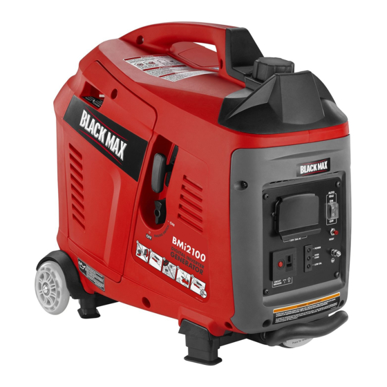
- Page 3 Fig. 1 A - On/off switch (interruptor de encendido y G - Ground terminal (terminal de conexión a M - Overload indicator (indicador de sobrecarga) apagado) tierra) N - Power indicator (indicador de potencia) B - Engine maintenance cover (cubierta de H - Retractable handle (mango retráctil) O - Auto idle switch (interruptor de ralentí...
- Page 4 Fig. 5 Fig. 7 Fig. 10 A - Starter grip and rope (mango del arrancador y cuerda) Fig. 8 A - On/off switch (interruptor de encendido y apagado) Fig. 11 B - Off (apagado) C - On (encendido) Fig. 6 A - On (encendido) B - Auto idle switch (interruptor de ralentí...
- Page 5 Fig. 13 Fig. 15 Fig. 14 A - Oil cap/dipstick (tapa de relleno de aceite/ varilla medidora de aceite) A - Fuel cap (tapa del tanque) B - Container (recipiente) B - Container (recipiente) A - Spark plug cap (tapa de la bujía) Fig.
-
Page 6: Table Of Contents
TABLE OF CONTENTS Introduction ..................................2 Important Safety Instructions ............................3-4 Specific Safety Rules ................................ 4 Symbols ..................................5-7 Electrical ..................................8-9 Features ..................................10 Assembly ..................................11 Operation ...................................12-14 Maintenance ................................15-17 Troubleshooting ................................18 ... -
Page 7: Important Safety Instructions
IMPORTANT SAFETY INSTRUCTIONS Do not start or operate the engine in a confined space, building, near open windows, or in other unventilated space DANGER: where dangerous carbon monoxide fumes can collect. Carbon Monoxide. Using a generator indoors CAN KILL Carbon monoxide, a colorless, odorless, and extremely YOU IN MINUTES. -
Page 8: Specific Safety Rules
IMPORTANT SAFETY INSTRUCTIONS Use only authorized replacement parts and accessories Maintain the unit per maintenance instructions in this and follow instructions in the Maintenance section of this Operator’s Manual. manual. Use of unauthorized parts or failure to follow Inspect the unit before each use for loose fasteners, fuel maintenance instructions may create a risk of shock or leaks, etc. -
Page 9: Symbols
SYMBOLS The following signal words and meanings are intended to explain the levels of risk associated with this product. SYMBOL SIGNAL MEANING Indicates an imminently hazardous situation, which, if not avoided, will result DANGER: in death or serious injury. Indicates a potentially hazardous situation, which, if not avoided, could result WARNING: in death or serious injury. - Page 10 SYMBOLS Some of the following symbols may be used on this product. Please study them and learn their meaning. Proper interpretation of these symbols will allow you to operate the product better and safer. SYMBOL NAME DESIGNATION/EXPLANATION Volts Voltage Amperes Current Hertz Frequency (cycles per second)
-
Page 11: Symbols
SYMBOLS ENGINE LUBRICANT WARNING You must add lubricant before first operating the generator. Always check the lubricant level before each operation. The lubricant level should always register between the hatched areas on the dipstick. The unit is equipped with a sensor which will automatically shut off the engine if the lubricant level falls below a safe limit. -
Page 12: Electrical
ELECTRICAL EXTENSION CORD CABLE SIZE Refer to the table below to ensure the cable size of the extension cords you use are capable of carrying the required load. Inadequate size cables can cause a voltage drop, which can damage the appliance and overheat the cord. Load in Watts Maximum Allowable Cord Length Current in... -
Page 13: Electrical
ELECTRICAL GENERATOR CAPACITY Never add more loads than the generator capacity. Take special care to consider surge loads in generator capacity Make sure the generator can supply enough continuous (run- as previously described. ning) and surge (starting) watts for the items you will power at the same time. -
Page 14: Features
FEATURES PRODUCT SPECIFICATIONS ENGINE GENERATOR Engine Type ......Single Overhead Cam (SOHC) Rated Voltage .........120 V AC/12 V DC Spark Plug ..........NHSP LD A7RTC Rated Amps ........14.16 A AC/7.5 A DC Cooling System ...........Forced Air Rated Running Watts ..........1,700 W Starting System ............ -
Page 15: Assembly
FEATURES RETRACTABLE HANDLE STARTER GRIP AND ROPE The generator is equipped with a retractable handle that can The starter grip and rope is used (along with the on/off switch) be adjusted for storage and transportation. to start the generator’s engine. ASSEMBLY UNPACKING WARNING:... -
Page 16: Operation
OPERATION NEVER use inside a home or garage, EVEN IF doors and DANGER: windows are open. Always position the generator on a flat firm surface. Carbon Monoxide. Using a generator indoors CAN KILL YOU IN MINUTES. SPECIAL REQUIREMENTS: Generator exhaust contains high levels of carbon There may be General or State Occupational Safety and monoxide (CO), a poisonous gas you cannot see or smell. - Page 17 OPERATION Unscrew the oil cap/dipstick and remove. When adding gas to the generator, make sure the unit is sitting on a flat, level surface. If the engine is hot, let the Wipe dipstick clean and re-seat in hole; do not re-thread. generator cool before adding gas.
-
Page 18: Operation
OPERATION Start the generator. WARNING: NOTE: The AC receptacles can be used while the DC receptacle is in use. While operating and storing, keep at least 3 feet of clear- The battery will become slightly warm to the touch while ance on all sides of this product, including overhead. -
Page 19: Maintenance
MAINTENANCE WARNING: WARNING: When servicing, use only identical replacement parts. Do not change engine lubricant while it is hot. Accidental Use of any other parts could create a hazard or cause contact with hot engine lubricant could result in serious product damage. - Page 20 MAINTENANCE DRAINING FUEL TANK/CARBURETOR DRAINING THE CARBURETOR See Figures 15 - 16. Turn off the generator. To help prevent gum deposits in the fuel system, drain the Loosen the screw at the top of the engine cover. Remove fuel from the tank and carburetor before storing.
-
Page 21: Maintenance
MAINTENANCE MAINTENANCE SCHEDULE NOTE: If a separate engine manual is provided for this generator, please follow the maintenance schedule provided in the engine manual instead of the maintenance information listed below. After 1st month Every 3 months Every 6 months Every year or Before or 20 hours of... -
Page 22: Troubleshooting
TROUBLESHOOTING PROBLEM POSSIBLE CAUSE SOLUTION Engine will not start. On/Off switch is OFF. Turn On/Off switch to ON. No fuel. Fill fuel tank. Stale gasoline or water in gasoline. Drain entire system and refill with fresh fuel. Lubricant level is low. Engine is equipped with Low Oil Shutoff. -
Page 23: Warranty
LIMITED WARRANTY WARRANTY COVERAGE OWT Industries, Inc., (the Company) warrants to the original retail purchaser that this Black Max Product is free from defects in material and workmanship and agrees to repair or replace, at the Company’s sole discretion, any defective Product free of charge within these time periods from the date of purchase: Two years, if the Product is used solely for personal, family, or household use;... - Page 24 WARRANTY CALIFORNIA AND EPA EMISSIONS CONTROL WARRANTY STATEMENT YOUR WARRANTY RIGHTS AND OBLIGATIONS (4) Repair or replacement of any warranted part under the warranty provisions herein must be performed at a warranty station at no The California Air Resources Board, United Sates Environmental Protection charge to the owner.
-
Page 25: Warranty
WARRANTY LIMITED ENGINE WARRANTY OWT Industries, Inc., (the Company), warrants that each new engine sold by it will be free, under normal use and service, from defects in material and workmanship for a period listed below from the date of sale to the original retail purchaser. - Page 26 NOTES Page 22 — English...
- Page 27 TABLA DE MATERIAS Introduction ....................................2 Instrucciones de seguridad importantes ..........................3-4 Reglas de seguridad específicas ............................... 4 Simbolos ....................................5-7 Aspectos eléctricos .................................8-9 Características ...................................10-11 Armado ..................................... 11 Funcionamiento ...................................12-14 Mantenimiento ..................................15-17 Corrección de problemas .................................
-
Page 28: Instrucciones De Seguridad Importantes
INSTRUCCIONES DE SEGURIDAD IMPORTANTES No haga arrancar o funcionar el motor en un espacio confi- nado, de edificio, cerca de ventana abiertas, o en otro área PELIGRO: sin ventilación donde se puedan recolectar las emanaciones de monóxido de carbono. El monóxido de carbono, un gas Monóxido de carbono. Usar un generador en el interior LO incoloro, inodoro y sumamente peligroso, puede causar la MATARÁ EN POCOS MINUTOS. pérdida de la conciencia o la muerte. Los gases de escape del generador contienen niveles altos Mantenga a todos los circunstantes, niños y animales por de monóxido de carbono (CO), un gas venenoso que no... -
Page 29: Reglas De Seguridad Específicas
INSTRUCCIONES DE SEGURIDAD IMPORTANTES ni cordones que muestren señales de daño, como roturas Use únicamente repuestos y accesorios autorizados y siga o agrietamientos en el aislamiento, o daño en las espigas. las instrucciones descritas en la sección de Mantenimiento de este manual. El empleo de piezas no autorizadas o el Los generadores fijos instalados de manera permanente incumplimiento de las instrucciones de mantenimiento puede son la mejor alternativa para abastecer de electricidad al significar un riesgo de descarga eléctrica o de lesiones. -
Page 30: Simbolos
SÍMBOLOS Las siguientes palabras de señalización y sus significados tienen el objeto de explicar los niveles de riesgo relaciona- dos con este producto. SÍMBOLO SEÑAL SIGNIFICADO Indica una situación peligrosa inminente, la cual, si no se evita, causará PELIGRO: la muerte o lesiones serias. Indica una situación peligrosa posible, la cual, si no se evita, podría causar ADVERTENCIA: la muerte o lesiones serias. Indica una situación peligrosa posible, la cual, si no se evita, podría causar PRECAUCIÓN: lesiones menores o leves. (Sin el símbolo de alerta de seguridad) Indica información importante no AVISO: relacionada con ningún peligro de lesiones, como una situación que puede ocasionar daños físicos. Es posible que se empleen en este producto algunos de los siguientes símbolos. Le suplicamos estudiarlos y aprender su significado. Una correcta interpretación de estos símbolos le permitirá utilizar mejor y de manera más segura el producto. SÍMBOLO NOMBRE DESIGNACIÓN/EXPLICACIÓN Alerta de seguridad Indica un peligro posible de lesiones personales. Para reducir el riesgo de lesiones, el usuario debe leer y comprender el Lea el manual del operador manual del operador antes de usar este producto. - Page 31 SÍMBOLOS Es posible que se empleen en este producto algunos de los siguientes símbolos. Le suplicamos estudiarlos y aprender su significado. Una correcta interpretación de estos símbolos le permitirá utilizar mejor y de manera más segura el producto. SÍMBOLO NOMBRE DENOMINACIÓN / EXPLICACIÓN Voltios Voltaje Amperios Corriente Hertz Frecuencia (ciclos por segundo) Watt Potencia Horas Tiempo Galón Volumen Cuarto Volumen ETIQUETAS DE SEGURIDAD La siguiente información puede encontrarse en el generador. Para su propia seguridad, le sugerimos estudiar y entender todas la etiquetas antes de poner marcha el generador.
- Page 32 SÍMBOLOS ADVERTENCIA DEL LUBRICANTE DE MOTOR Antes de utilizar el generador debe abastecerlo de lubricante. Antes de utilizar la unidad, revise el nivel de lubricante. El nivel de lubricante siempre debe estar entre las áreas cubierta con rayas entrecruzadas de la varilla de nivel. La unidad está equipada de un sensor, el cual apaga automáticamente el motor si el nivel de lubricante desciende abajo del límite de seguridad. ADVERTENCIA ACERCA DE LA CONEXIÓN A TIERRA El Reglamento Nacional de Electricidad exige que el generador esté conectado a una tierra aprobada. ADVERTENCIA DE SUPERFICIE CALIENTE No toque el silenciador ni el cilindro de aluminio del motor. Están muy CALIENTES y causan quemaduras graves. No ponga ningún material inflamable o combustible directamente en la...
-
Page 33: Aspectos Eléctricos
ASPECTOS ELÉCTRICOS CALIBRE DEL CORDÓN DE EXTENSIÓN Consulte el cuadro mostrado abajo para asegurarse de que el calibre de los cordones de extensión que utilice puedan con la carga eléctrica requerida. Los cordones de calibre insuficiente pueden causar una caída de voltaje, lo cual puede quemar el dis- positivo y recalentar el cordón mismo. Carga en vatios Longitud máxima permitida del cordón Corriente en Amperios A 120 V A 240 V Conduct. #8 Conduct. #10 Conduct. #12 Conduct. #14 Conduct. #16 305 m (1000 pies) 183 m (600 pies) 114 m (375 pies) 76 m (250 pies) - Page 34 ASPECTOS ELÉCTRICOS Debido a que no todos los motores arrancan al mismo AVISO: tiempo, se puede calcular la potencia inicial total en vatios sumando sólo los equipos con el mayor valor de No exceda la capacidad del generador. Si excede la potencia inicial adicional a la potencia nominal del paso 2. capacidad de corriente (amperios) y potencia (vatios) del Ejemplo: generador puede dañar el generador y los dispositivos eléctricos conectados al mismo. Potencia Potencia arranque Herramienta o...
-
Page 35: Características
CARACTERÍSTICAS ESPECIFICACIONES DEL PRODUCTO GENERADOR MOTOR Voltaje nominal ........120 V C.A/12 V C.C. Tipo de motor ......Leva única elevada (SOHC) Amperaje nominal......14,16 A C.A/7,5 A C.C. Bujía............NHSP LD A7RTC Potencia en marcha ..........1 700 W Sistema de enfriamiento........Aire forzado Potencia de arranque ..........2 100 W Sistema de arranque .......... -
Page 36: Armado
CARACTERÍSTICAS MANGO RETRÁCTIL MANGO DEL ARRANCADOR Y CUERDA El generador está equipado con un mango retráctil que Con un tirón del mango del arrancador y cuerda se arranca puede ajustarse para el almacenamiento y el transporte. el motor. ARMADO DESEMPAQUETADO ADVERTENCIA: Embarcamos este producto completamente armado. Si falta o está dañada alguna pieza, no utilice este Extraiga cuidadosamente de la caja la herramienta y los producto sin haber reemplazado la pieza. Usar este accesorios. Asegúrese de que estén presentes todos los... -
Page 37: Funcionamiento
FUNCIONAMIENTO ANTES DE ACCIONAR LA UNIDAD PELIGRO: Sólo utilícelo AL AIRE LIBRE y lejos de ventanas, puertas y respiraderos. Monóxido de carbono. Usar un generador en el interior LO MATARÁ EN POCOS MINUTOS. NUNCA lo use dentro de su hogar o del garaje, INCLUSO con las puertas y las ventanas abiertas. Los gases de escape del generador contienen niveles altos de monóxido de carbono (CO), un gas venenoso Coloque siempre el generador sobre una superficie firme plana. que no puede verse ni olerse. Si puede oler los gases de REQUISITOS ESPECIALES: escape del generador, está respirando CO. Pero incluso Es posible que se apliquen reglamentaciones de la si no puede oler los gases de escape, es posible que Administración de Salud y Seguridad Ocupacional... - Page 38 FUNCIONAMIENTO Etanol. Las gasolinas con un contenido de 10% de etanol por aceite SAE 10W-30. Siempre utilice lubricante para motor de volumen (comunmente conocida como E10) es aceptables. Las cuatro tiempos que satisfaga o sobrepase los requisitos SJ de gasolinas E15 y E85 no lo son. clasificación de servicio API. NOTA: El lubricante sin detergente o para motor de dos tiempos VERIFICACIÓN Y ABASTECIMIENTO DE daña el motor, por lo cual no debe usarse. COMBUSTIBLE Retire el tornillo de la parte superior de la cubierta de Vea las figuras 4 y 5. mantenimiento del motor. Retire la cobertura y hágala a un lado (vea la fig. 14).
- Page 39 FUNCIONAMIENTO NOTA: Cuando el interruptor de encendido/apagado está positiva (+) y el cable negro con la terminal negativa (–). en la posición ENCENDIDO (I), el combustible circulará Asegúrese de que todas las conexiones estén firmes. desde el tanque de combustible hasta el motor. NOTA: Teniendo cuidado de no causar cortocircuito en las Desplace izquierda de la palanca del anegador hasta la terminales. Un cortocircuito al juntar las terminales puede posición START (ARRANQUE).
-
Page 40: Mantenimiento
MANTENIMIENTO Retire el tapón de drenaje del aceite y drene el aceite ADVERTENCIA: viejo. Incline el generador para permitir que el lubricante drene Al dar servicio a la unidad, sólo utilice piezas de repuesto por el agujero de llenado de aceite en un contenedor idénticas. El empleo de piezas diferentes puede causar aprobado. un peligro o dañar el producto. NOTA: Drene el aceite mientras esté tibio el motor, no MANTENIMIENTO GENERAL caliente. El aceite tibio se drena con mayor facilidad y compleción. - Page 41 MANTENIMIENTO Apriétela con una llave para comprimir la arandela. Si Una vez que se haya drenado todo el combustible del es nueva la bujía, gírela 1/2 vuelta para comprimir al tanque, reemplace la tapa del tanque de combustible. nivel adecuado la arandela. Si va a volver a usar la bujía DRENAJE DEL CARBURADOR vieja, gírela de 1/8 a 1/4 de vuelta para comprimir al nivel Apague la generador. adecuado la arandela. Retire el tornillo de la parte superior de la cubierta del NOTA: Si no se aprieta debidamente, la bujía se calienta motor. Retire la cobertura y hágala a un lado.
- Page 42 MANTENIMIENTO PROGRAMA DE MANTENIMIENTO NOTA: Si recibe un manual del motor para este generador en particular, respete el cronograma de mantenimiento que se indique en el manual del motor y no la información de mantenimiento que figura a continuación. Al cabo del Cada año Cada 3 meses Cada 6 meses Antes de primer mes o o luego de o 50 horas de o 100 horas de cada uso 20 horas de...
-
Page 43: Corrección De Problemas
CORRECCIÓN DE PROBLEMAS PROBLEMA CAUSA POSIBLE SOLUCIÓN El motor no arranca. El interruptor de encendido y apagado Ponga el interruptor de encendido y apagado en está en apagado (OFF). encendido (ON). No hay combustible. Llene el tanque de combustible. Gasolina pasada o agua pasada en la Drene todo el sistema y reabastézcalo con combus- gasolina. -
Page 44: Garantía
Para obtener el servicio de garantía: Llame sin cargo al 1-800-726-5760 o escriba a OWT Industries, Inc., P.O. Box 35, Hwy. 8, Pickens, SC 29671. Para obtener el servicio de garantía fuera de los EE. UU., comuníquese con el establecimiento Black Max local. Página 19 — Español... - Page 45 GARANTÍA DECLARACIÓN DE GARANTÍA DEL CONTROL DE EMISIONES DE CALIFORNIA Y EPA SUS DERECHOS Y OBLIGACIONES EN RELACIÓN CON LA GARANTÍA (5) Sin perjuicio de los términos aquí expuestos, el mantenimiento o las reparaciones relacionados con la garantía serán realizados en todos La Junta de Recursos del Aire de California (CARB), la Agencia de Protección nuestros centros de distribución que estén habilitados para realizar Ambiental de los Estados Unidos (EPA) y Zhejiang ZhongJian Technology Co., mantenimiento a los motores en cuestión.
- Page 46 GARANTÍA DECLARACIÓN DE GARANTÍA LIMITADA AL MOTOR OWT Industries, Inc., (la Compañía), garantiza al comprador minorista original que cada motor nuevo que se venda carecerá de defectos en material y mano de obra bajo condiciones normales de servicio y uso durante el período mencionado abajo a partir de la fecha de venta. La obligación de La Compañía bajo esta Garantía limitada cubre únicamente la reparación y el reemplazo, a elección de La Compañía, de las partes que, luego de ser examinadas, resulten, a criterio de La Compañía defectuosas en material o mano de obra. Una condición de la obligación deLa Compañía obligation under this Limited Warranty that La Compañía, bajo esta Garantía Limitada será que esta empresa directamente o a través de uno de sus Distribuidores o Centros de Servicio autorizados a realizar el servicio del motor en cuestión, reciban una notificación inmediata de cualquier reclamo de la garantía y que el motor, o las partes presuntamente defectuosas, se envíen inmediatamente con el transporte pagado por adelantado a dicho Distribuidor o Centro de Servicio para realizar la inspección y reparación. Todas las reparaciones que califiquen bajo esta Garantía limitada deben ser realizadas por La Compañía, o uno de sus Distribuidores o Centros de Servicios autorizados. PERÍODOS DE GARANTÍA: Garantía limitada de dos años del motor de gasolina ZJ158F (privado o residencial) Garantía limitada de 90 días de motores de gasolina ZJ158F (comerciales).
- Page 47 NOTAS Página 22 — Español...
- Page 48 CALIFORNIA PROPOSITION 65 SERVICE WARNING: For parts or service, contact your nearest Black Max authorized service dealer. Be sure to provide all relevant information when you call or visit. For the loca- This product, its exhaust, and other tion of the authorized service dealer nearest you, please call 1-800-726-5760.
Need help?
Do you have a question about the BMi2100 Series and is the answer not in the manual?
Questions and answers