Table of Contents
Advertisement
Quick Links
Advertisement
Table of Contents

Related Manuals for Jet JVM-836


Summary of Contents for Jet JVM-836
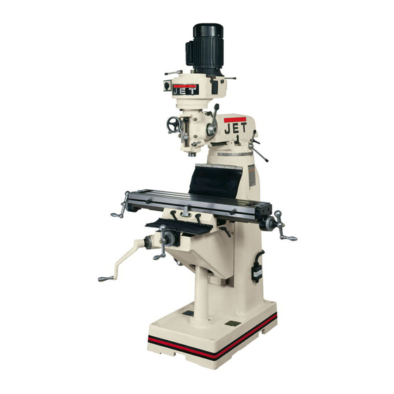
- Page 1 This .pdf document is bookmarked Operating Instructions and Parts Manual Step-Pulley Turret Mill Model JVM-836 427 New Sanford Road LaVergne, Tennessee 37086 Part No. M-690036 Ph.: 800-274-6848 Revision D 03/2016 www.jettools.com Copyright © 2014 JET...
-
Page 2: Warranty And Service
JET sells through distributors only. The specifications listed in JET printed materials and on official JET website are given as general information and are not binding. JET reserves the right to effect at any time, without prior notice, those alterations to parts, fittings, and accessory equipment which they may deem necessary for any reason ®... -
Page 3: Table Of Contents
13.4.1 JVM-836 Base Assembly – Exploded View ..................25 13.4.2 JVM-836 Base Assembly – Parts List ....................26 13.5.1 JVM-836 One Shot Lubrication System – Exploded View ..............28 13.5.2 One Shot Lubrication System – Parts List ................... 28 ... -
Page 4: Safety Warnings
19. Disengage power feed when not in use. 5. Do not use this turret mill for other than its intended use. If used for other purposes, JET 20. Remove adjusting keys and wrenches. Form a disclaims any real or implied warranty and... -
Page 5: About This Manual
If there are questions or comments, please contact your local supplier or JET. JET can also be reached at our web site: www.jettools.com. -
Page 6: Specifications
Shipping Weight (approx) ................ 1700 lb........... 1700 lb The specifications in this manual were current at time of publication, but because of our policy of continuous improvement, JET reserves the right to change specifications at any time and without prior notice, without incurring obligations. -
Page 7: Jvm-836 Installation Layout
6.0 JVM-836 Installation Layout Figure 1... -
Page 8: Setup And Assembly
7.0 Setup and Assembly 7.2 Contents of shipping container Refer to Figure 2. 7.1 Unpacking Turret Mill (not shown) Open shipping container and check for shipping Flat Way Cover (rear) damage. Report any damage immediately to your Pleated Way Cover (front) distributor and shipping agent. -
Page 9: Site Preparation
7.3 Site preparation Mill must be supported equally The mill must be placed on an even surface and under all four corners. Failure to comply may bolted to the floor. Anchor bolts of sufficient size cause the column to twist and put a bind in the and length must be fastened to the floor according ways. -
Page 10: Lubrication
Mobil DTE® Oil Light. 8.1 Conversion from 115V to 230V B. Oil Pump – Fill reservoir as needed by (JVM-836-1 only) removing cap on top of tank and filling with Mobil Vactra Oil No. 2. Pump oil release To convert from 115V to 230V operation, remove handle once for every hour of operation. -
Page 11: Wire Sizes
Fine Feed Engagement (I, Figure 7) – Turn 8.2 Wire Sizes clockwise until tight. This engages the manual fine feed; counterclockwise to release. For circuits which are far away Draw Bar (J, Figure 7) – Located at top of from the electrical service box, the wire size must head. -
Page 12: Operation
Figure 9 10.3 Changing speeds 1. Unscrew two knobs (A, Figure 7) and remove belt cover. Figure 8: controls 2. Loosen hex nut (A, Figure 10). 3. Release tension from belt by moving lever (B, 10.0 Operation Figure 10). 4. Move belt to desired position, by referring to 10.1 Precautions speed chart on the belt cover. -
Page 13: Draw Bar Operation; Changing Tooling
Note: Due to variables in tool diameter, coatings, Be sure to apply torque in coolant, and materials, no specific spindle speed or two steps using a crossing pattern. Failure feed rate recommendations are provided. Use to do so could distort the face of the ram general shop manuals that have data applicable to adapter. -
Page 14: Positioning Ram
11.2 Positioning ram NOTE: When adjusting gibs, always start with the knee first; adjust the saddle second, and adjust the 11.2.1 Sliding ram fore and aft table last. 11.3.1 Knee gib Care should be taken to lock ram securely after setting. Loosen the two knee locking handles. - Page 15 11.5.1 Cross feed backlash adjustment 11.5.2 Longitudinal backlash adjustment Refer to Figure 14: Refer to Figure 14: 1. Use cross feed crank to move table to extreme Only one of the longitudinal lead screw nuts can be rear of its travel (toward column). adjusted;...
-
Page 16: Speed Charts For Jvm-836
12.0 Speed charts for JVM-836 The charts below are also found on the mill head of the respective models. SINGLE PHASE ONLY 3-PHASE ONLY Figure 15 Figure 16 13.0 Replacement Parts Replacement parts are listed on the following pages. To order parts or reach our service department, call 1- 800-274-6848 Monday through Friday, 8:00 a.m. -
Page 17: Jvm-836 Head Assembly - Exploded View
13.1.1 JVM-836 Head Assembly – Exploded View... -
Page 18: Jvm-836 Head Assembly - Parts List
13.1.3 JVM-836 Head Assembly – Parts List Index No Part No Description Size 1 ....JVM836-01 ....Castle Nut ..............M12 ....... 1 2 ....JVM836-02 ....Lock Nut......................1 3 ....TS-1523041 ....Hex Socket Cap Screw ..........M6x12 ......3 4. - Page 19 Index No Part No Description Size 52 ....JVM836-52 ....Hand Grip ...................... 1 53 ....TS-1523041 ....Set Screw ..............M6x10 ......1 54 ....JVM836-54 ....Locating Block ....................1 55 ....JVM836-55 ....Hex Socket Cap Screw ..........3/8-24UNF ....1 56 ....
-
Page 20: Jvm-836 Upper Head Assembly - Exploded View
13.2.1 JVM-836 Upper Head Assembly – Exploded View... -
Page 21: Jvm-836 Upper Head Assembly - Parts List
13.2.2 JVM-836 Upper Head Assembly – Parts List Index No Part No Description Size 2 ....VM-G22-1....Spacer ......................1 3 ....VM-G22 ..... Draw Bar ......................1 4 ....VM-M3-1 ....Knob (s/n XXX0049 and lower) ..............1 .... - Page 22 49 ....VM-M2-2 ....Cross Round Cap Screw ................2 50 ....JVM836-U50 ..... Plastic Electrical Box ..................1 51 ....JVM836-U51 ..... Cross Round Cap Screw ......... M5x40L ......2 52 ....JVM836-N01G ..JET Label....................... 1...
-
Page 23: Jvm-836 Leadscrew Assembly - Exploded View
13.3.1 JVM-836 Leadscrew Assembly – Exploded View... -
Page 24: Jvm-836 Leadscrew Assembly - Parts List
13.3.2 JVM-836 Leadscrew Assembly – Parts List Index No Part No Description Size 1 ....VM-I1......Castle Nut ..............M12 ....... 3 2 ....VM-I2G ...... Handle ......................3 3 ....VM-I2-1G....Ball Handle ....................3 4 ....VM-I3......Knurled Nut (s/n XXX0049 and lower) ............3 .... -
Page 25: Jvm-836 Base Assembly - Exploded View
13.4.1 JVM-836 Base Assembly – Exploded View... -
Page 26: Jvm-836 Base Assembly - Parts List
13.4.2 JVM-836 Base Assembly – Parts List Note: Some index numbers in this parts list have two part numbers. If your milling machine has the serial number 0040050 and higher, use the part number ending with a “T.” If your milling machine has the serial number xxx0049 and lower, use the part number without the letter “T.”... - Page 27 Index No Part No Description Size 47 ....VM-J20 ...... Saddle Gib ..................... 1 48 ....VM-J30 ...... Table Stop Bracket ..................1 49 ....TS-1515021 ....Hex Socket Cap Screw ..........M8x20 ......2 50 ....VM-J29-1....Shoe ......................2 51 ....
-
Page 28: Jvm-836 One Shot Lubrication System - Exploded View
13.5.1 JVM-836 One Shot Lubrication System – Exploded View 13.5.2 One Shot Lubrication System – Parts List Index No Part No Description Size 1 ....JVM836-HP ....Hand Oiling Pump..................1 2 ....JVM836-ALMP ..Aluminum Pipe............Ø4 ......... 1 3 .... -
Page 29: Electrical Connections For Jvm-836
14.0 Electrical Connections for JVM-836... - Page 30 This page intentionally left blank.
- Page 31 This page intentionally left blank.
- Page 32 427 New Sanford Road LaVergne, Tennessee 37086 Phone: 800-274-6848 www.jettools.com...
Need help?
Do you have a question about the JVM-836 and is the answer not in the manual?
Questions and answers